Abstract
We report the feasibility of using electrospray to atomize dense suspension of nanoparticles with high solid concentrations. We demonstrate this principle through electrospraying dense suspensions of TiO2 nanoparticles with 40 wt.% in ethylene glycol. A dye sensitized solar cell (DSSC) is fabricated by electrospray deposition and the power conversion efficiency up to 6.81% is demonstrated. This simple, one-step process can fabricate the active layer with uniform thickness and multiple length scales, including 25 nm TiO2 nanoparticles, ∼2 μm micro spherical particles, and ∼20-μm-thick film. A judicious choice of drying temperature is important to ensure complete drying of suspension droplets while avoiding creation of hollow particles, because the hollow particles exhibit significantly lower carrier mobility and short circuit current. The very high solid concentration demonstrated in this work can potentially reduce the manufacturing cost of DSSC because less energy will be wasted on evaporating and/or recycling the organic solvent. In addition, because electrospray is compatible with roll-to-roll process and the yield is scalable through multiplexed electrosprays, the electrospray route is a promising and economically competitive approach for manufacturing DSSCs through spray deposition.
Copyright 2013 American Association for Aerosol Research
1. INTRODUCTION
Dye-sensitized solar cells (DSSC) (O’Regan and Grätzel Citation1991; Bach et al. Citation1998; Hagfeldt and Grätzel Citation2000; Grätzel Citation2001; Grätzel et al. 2001) are promising direct solar energy conversion devices, with satisfactory long-term stability (Yella et al. 2011) and high efficiency reaching 12.3% (Aswani et al. 2011), which is the highest among organic solar cells. Photo-electrode film of metal oxide nanoparticles (typically TiO2) in DSSC plays a major role in the light absorption and charge carrier separation/collection process. Popular fabrication methods of the photo-electrode film include screen-printing (O’Regan and Grätzel Citation1991; Grätzel Citation2001), spray-coating (Peng et al. Citation2004), spin-coating (Papageorgiou et al. Citation1997; Pichot et al. Citation2000), and blade-coating (Ding et al. Citation2010). The strength and weakness of those methods are summarized in some excellent review papers (Ito et al. 2008, Zhang et al. 2009).
Recently electrospray (ES) has emerged as a powerful tool in organic photovoltaics fabrication (Zhao et al. Citation2012) because of its unique advantages such as the ability of operating in atmospherically pressure, easy integration into roll-to-roll production, less material loss (Deng and Gomez 2010), and self-organized nano structures. ES is an electrohydrodynamic liquid atomizing technique that can generate monodispersed droplets of a few nm to 100 μm. A typical ES system can be implemented by feeding a liquid with sufficient electric conductivity, such as ethanol, through a small capillary, which is charged to a high potential relative to a nearby ground electrode. When the normal electric stress balances the liquid-air interfacial stress, the liquid meniscus at the nozzle tip may take a conical shape, which is termed Taylor-cone (Taylor Citation1964). The electric shear stress drives the liquid near the free surface and accelerates the bulk liquid and form a fine jet at the cone apex. The jet undergoes Rayleigh instability and breaks up into primary and satellite droplets (). The satellite droplets typically are 1/3 to 1/2 of the size of the primary droplets (Fernández 2007), and the weight percentage of droplets will be ∼10% or less of the entire spray (Tang and Gomez Citation1994). In view of the liquid meniscus morphology, this regime is labeled cone-jet mode (Cloupeau and Prunet-Foch 1990). Although the con-jet electrospray has a major drawback of low flow rate (typically on the order of 1 mL/h or less), the overall throughput can be increased by massively multiplexed electrospray (Deng et al. Citation2006, Citation2009).
The ES emits one droplet a time through the breakup of liquid jet attached to the Taylor cone. Each droplet generated by the ES may contain zero, single, or multiple TiO2 particles, depending on the concentration of solid particles. This discrete deposition fashion allows formation of substructure within the film, which cannot be achieved through conventional methods such as doctor-blading or spin coating. For example, during ES deposition, TiO2 needle bundles can be formed (Fujimoto et al. Citation2006) that lead to higher short circuit current JSC. In addition, the ES process can be combined with other preprocessing (Sudhagar et al. Citation2011) or postprocessing (Zhang et al. Citation2009) approach to further increase the device performance. Zero dimensional (0-D) hierarchically-structured TiO2 (HS-TiO2) were suggested as optimal morphologies for DSSCs due to the advantages of large surface area and dye adsorption, fast electron transport at reduced grain boundaries, light scattering effects of the nanostructures, and better penetration of electrolytes through the relatively large pores between spheres (Chou et al. Citation2007; Chen et al. Citation2009; Kim et al. Citation2009; Huang et al. Citation2010; Hwang et al. Citation2011; Zhang et al. 2009). Hwang et al. succeeded in demonstrating HS-TiO2 spherical clusters of 200 nm to 1000 nm using the ES method and reported power conversion efficiency (PCE) as high as 10.57% (Hwang et al. Citation2011). They attribute the high efficiency to the HS-TiO2 spheres, which form mesopores and improve the electrolyte penetration and diffusion.
Despite the progress in ES route for DSSC fabrication, one concern is the low concentration used in many of the ES process. To make stable suspensions, the TiO2 nanoparticle concentrations reported in the literature are typically below 10wt.%. For example, in the above mentioned hierarchically-structured TiO2 example (Hwang et al. Citation2011), the concentration is estimated at 0.1 vol.% (based on dried spherical particle size of 1000 nm and droplet size of about 10 μm according to the reported ethanol flow rate of 2mL/h and size scaling laws of ethanol ES). This volume concentration is consistent with other related work of electrospraying TiO2 nanoparticle suspensions, in which the volume fraction of the solid nanoparticles is 0.01% to 0.4% (Hogan and Biswas Citation2008; Modesto-Lopez and Biswas Citation2010). In these works, for each part of solid film to be deposited, 250 to 10,000 parts of solvent must be evaporated. The low solid concentration associated with typical ES process may eventually hinder the scale-up production of DSSC solar cells due to the added cost of waste energy and vapor recycling burden associated with solvent evaporation. Although some existing film fabrication methods, such as doctor blading and spin coating, can process dense suspension in paste or slurry form, the produced films are homogeneous and lack ordered micro structures. Therefore, increase of the solid concentration in the suspension will make the ES route more competitive while keeping the hierarchically structured TiO2 spherical clusters.
In this article, we report a fabrication method for DSSC photo electrode based on electrospraying dense suspension of TiO2 nanoparticles. The solid concentration is increased to 40 wt.% with ethylene glycol as the solvent. Here the “solvent” in fact refers to the liquid media used to make the nanoparticle suspension. The high concentration may greatly reduce the amount of solvent and the thermal energy required for solvent removal in large-scale manufacturing. The evaporation of the dense suspension droplet leads to solid spherical micro clusters of ∼3 μm. The device made from this approach reaches the PCE of 6.81%.
2 EXPERIMENTS
2.1 Electrospray Setup of the Dense Suspension and Spray Characterization
To form dense yet stable TiO2 suspension with homogeneous dispersion, we performed multiple try-and-error tests, and the final formula is to mix 6 g TiO2 nanoparticles (P25, Degussa) in 8 g ethylene glycol (EG) and 1 g acetic acid (Sigma Aldrich, reagent grade, >99.7%). The choice of the weight ratios of those ingredients is an empirical compromise between increasing TiO2 concentration and maintaining sufficient fluidity of the suspension. Mixing more TiO2 nanoparticles in EG results in highly viscous paste that frequently clogs the fluid line and nozzle. We choose ethylene glycol as the dispersing liquid because it has ∼20 times higher viscosity than ethanol, which was the typical solvent used in previous ES DSSC work. The dense TiO2 suspension in EG is highly stable without observable settling for over 48 h. Acetic acid is added to increase k (the electrical conductivity) of the liquid, because we aim to generate smaller droplet size (see Section 3.1 for details). Similar strategy has been adopted by other researchers in increasing the conductivity of dilute suspension and preventing particle settling (Hogan and Biswas Citation2008; Modesto-Lopez and Biswas Citation2010). The electric conductivity of the suspension is measured at 0.02 S/m, which is about two orders of magnitude higher than that of pure EG. The mixture is stirred for 24 h by a magnetic stirrer. Then this suspension is loaded into a syringe.
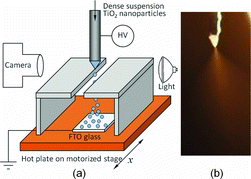
shows the schematic of the experimental setup. The ES source is a stainless steel needle with 0.71 mm outer diameter and 0.29 mm inner diameter. The ES source is connected to the output of a high voltage power supply, and the tip of the needle is placed about 4.5 cm above the substrate. The typical voltage applied is 4.5 kV, with ES flow rate at 0.05 mL/h. The operating environment was air at atmospheric pressure. No charge neutralization mechanism was introduced. The ES quality is monitored in real time by a video microscope camera to ensure good cone-jet operation. An example of the Taylor cone image under the reported experimental conditions is shown in . The Taylor cone in exhibits white translucent color due to the high concentration of TiO2 nanoparticles. The liquid jet that connects the Taylor cone and the fine spray plume appears to be very short, which is a typical behavior for electrospraying with highly conducting liquids.
The droplet diameter at various flow rates is characterized using Phase Doppler Interferometry (PDI) (Artium) operated in reflection mode because the droplets are optically opaque. To measure the size and velocity of the droplets emanating from the nozzle, the device was mounted on a 3-axis micrometer to position the spray cloud in the PDI probe volume. For each measurement, we positioned the laser probe volume at or near the spray axis where the data rate is the highest. Note that PDI is point measurement and the size measured near the spray axis is mostly the primary droplets. We took 2000 primary droplet samples and recorded the simply averaged droplet diameter D10 and the relative standard deviation (RSD) of D10. RSD is typically less than 12%, which indicates quasimonodispersity. Although the RSD of the entire spray (both primary and satellite droplets) will be larger than the RSD of D10, the D10 and RSD reported are still representative because the primary droplets have dominant mass (>90%) in a cone-jet electrospray.
The substrate is fluorine-doped tin oxide (FTO) glass (2 cm × 1.5 cm), which severs as optically transparent electrode. The FTO glass is precleaned by 15-min ultrasonic bath in ethanol, followed by 15-min wash with deionized water, and 1-min oxygen plasma treatment. The FTO is connected to the ground of the high voltage power supply. The substrate is heated by a hot plate, with surface temperature monitored by a K-type thermocouple, and the temperature is controlled by a PID controller. The temperature can reach up to 300°C, and we focus on two representative temperatures of 150°C and 250°C, for reasons to be discussed in Section 3.2. To maintain a “hot” zone above the substrate and promote complete solvent evaporation, we built a rectangle enclosure covered with fiber glass insulation layer. A slot opening of 5-mm width at the top of the enclosure allows the spray to enter the hot zone. The enclosure also effectively shields the hot plate from heating the liquid cone.
The hot plate is mounted on a three dimensional translational stage, which enables us to automatically adjust the distance between the ES nozzle and the substrate, as well as moving the substrate with steady motion controlled by the computer. The substrate moving speed used in this work is about 4 mm/min.
2.2 DSSC Fabrication and Characterization
After deposition, we follow the protocol established in Ito et al. (2008) to finish the device. Briefly, the coated side of titanium dioxide electrode is dipped into TiCl4 in a shallow petri dish for 40 min at 75°C and then dried. Next, the electrode is soaked by 1 M acetic acid for 16 h. This acetic treatment is inspired by other researchers (Hao et al. Citation2004) who found that the DSSC efficiency can be improved by treating the electrode with hydrochloric acid of low concentration (0.1 M). They attributed the enhancement of efficiency to the refreshed surface of TiO2 nanoparticles, which benefits the absorption to dye molecules. Then the electrode is sintered at 500°C, and is subsequently soaked in N719 dye for 48 h. The counter electrode is made by pyrolysis of platinum paste (Dyesol) at 420°C for 15 min. Then the two electrodes are aligned and sealed by epoxy, followed by injection of electrolyte. To perform the I-V characterization test, we place the solar cells under a Xenon light-powered solar simulator with air mass (AM) 1.5 filter. The illumination intensity is 100 W/m2. The I-V curve is recorded by a Keithley 2400 source meter.
The morphology of the TiO2 photoelectrode is visualized by scanning electron microscope (SEM). The detailed internal nano/micro structure of the TiO2 micro particles is analyzed by creating cross-section using focused ion beam (FIB).
3 RESULTS AND DISCUSSION
3.1 Characterization of the Electrospray of Dense Suspension
We first characterize the droplet diameter at different flow rates of the dense suspension. The droplet diameter is a fundamental parameter for this work because the final particle size is proportional to the initial droplet diameter and the cubic root of solid content concentration φ1/3D, where φ is the volumetric concentration of the solid content and D is the initial diameter of the liquid droplet. At high concentration, φ1/3 is of order 1, and the particle size is therefore comparable with the droplet diameter. In addition, D also determines the evaporation time te that scales with D2. This relationship is particularly important in creating the hierarchical TiO2 film, because the droplets need to be completely dried before reaching the substrate. To that end, the residence time tr of the droplets should be longer than te. Since te∝D2, a small decrease in droplet diameter can lead to dramatic reductions in the evaporation time, which, in turn, enables shorter droplet residence time, shorter nozzle-substrate distance, and lower operating voltages.
The droplet diameter of the electrospray is usually inferred from the so-called scaling laws that have been derived by dimensional and theoretical analysis, such as in (Fernández de la Mora and Loscertales Citation1994) as well as numerical asymptotic analysis (Higuera Citation2003). The scaling law for droplet size at high conductivity regime yields D∝(Q k)1/3, where Q is the liquid flow rate. This relationship suggests that both the liquid flow rate Q and the electrical conductivity k can control the droplet size. The flow rates of a single electrospray cannot be arbitrarily small because it is bounded by the minimum flow rates that the cone-jet mode can sustain, as well as the consideration of sufficient throughput. This leaves us with the only option of increasing liquid conductivity to achieve the goal of generating smaller droplets. Although the addition of TiO2 nanoparticles will increase the conductivity of suspension compared to pure solvents (Modesto-Lopez and Biswas Citation2010), the effect is not as significant as adding acid. This is the primary reason that the acetic acid is added to the suspension, because the acetic acid boosts the conductivity by over 100 folds compared to the pure EG. In doing so, we reduced the droplet size by a factor of ∼5.
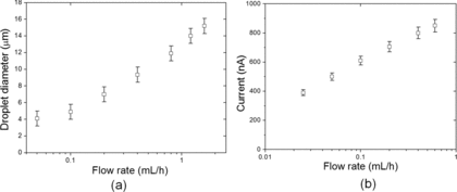
The measured droplet diameter as a function of flow rate is reported in . Majority of the data form approximately a straight line on the plot with log scale, indicating a power law dependence of the droplet diameter to the flow rate. This is consistent with the scaling laws mentioned previously. We pointed out that the droplet size at 0.05 mL/h deviates noticeably from the trend of the rest of the data, and currently we lack a definite explanation for it. One hypothesis is that the nonlinear viscosity significantly affects the jetting and breakup of the Taylor cone, therefore the size scaling law can no longer accurately describe droplet diameter at very low flow rates. The current emitted by the electrospray at different flow rates also forms a straight line (), as similar power laws of current scaling also apply. By electrospray standards, the current is on the high end (>200 nA), which is expected at high liquid conductivity.
3.2 Effect of Thermal History on the Particle Morphology
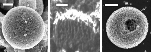
It has been well documented in the literature that the particle morphology is determined by the relative importance of characteristic times of the heat and mass transfer process (Vehring et al. Citation2007). In the ES process, the Damkhöler number of evaporation (Almeria et al. Citation2010) (the ratio of droplet residence time and evaporation time) and the Peclet number (the ratio of the evaporation time and intradroplet diffusion time) play a key role on the dried particle morphology. On the other hand, the temperature field inside the hot enclosure strongly affects the evaporation time; therefore, both Damkhöler number and Peclet number are strongly connected to the thermal history of the droplet. Our goal is to produce dense and spherical micro aggregates of TiO2 nanoparticles. Because the initial average droplet size is the same due to identical flow rates (0.05 mL/h), the temperature will affect the evaporation rate as well as evaporation time. For the experimental conditions used in this work, when the temperature of the hot plate is lower than 130°C, the evaporation time is too long and the droplets are still not fully evaporated, and a dense film lack of hierarchical structure is formed. When the substrate temperature is increased to 150°C, the evaporation of ethylene glycol is generally complete, thus as the droplet is converted into spherical micro particles by the time of impact on the substrate, as shown in . The cross-section sample prepared using FIB () reveals the internal structure of the spherical micro aggregates under such condition is solid, despite the porous appearance at the surface in . At even higher temperature such as 250°C, which is significantly higher than the boiling point of EG (197.3°C), the solvent evaporation becomes too rapid, we start getting spherical shells which are cracked upon impact on the substrate ().
3.3 Improving the Uniformity of the Film Thickness Through Relative Motion
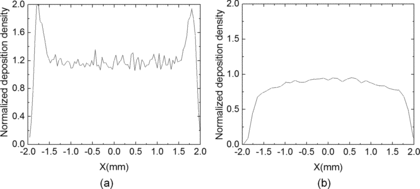
For a single ES, the spray plume is relatively hollow at the center, namely the number density at the edge of the spray is as much as twice of that inside the spray (Tang and Gomez Citation1994; Wilhelm et al. Citation2003; Oh et al. Citation2008). This suggests that it is difficult to produce TiO2 photoelectrode of uniform thickness with a stationary ES. To overcome this problem, we introduce relative motion between the ES source and the substrate. shows the numerical simulation of the number density of a typical ES along the diameter of the circular deposition footprint. The numerical simulation of the spray interaction was conducted using a Lagrangian droplet tracking model (Yang et al. Citation2012). The model simulates the trajectory of all droplets just after jet break-up. Lagrangian method has been well documented previously (Ganan-Calvo et al. Citation1994; Hartman et al. Citation1999; Wilhelm et al. Citation2003; Yang et al. Citation2012) and the details will not be repeated here. When the ES is stationary relative to the substrate, the deposition exhibits double peaks of the number density. If the linear relative motion is introduced, the deposition becomes more uniform (). The reason for this is that the edge of the spray has a higher droplet flux but accounts for much less area. This combined effect smoothes out the double peaks and a more uniform mass flux across the spray diameter can be achieved. Thus,
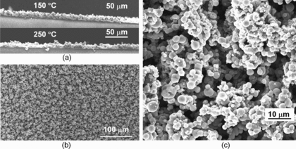
shows the typical SEM images of the electrode fabricated by electrospraying dense TiO2 suspensions to a moving substrate heated at 150°C. The side view () of the deposited film shows decent film uniformity with a thickness of 16 ± 2 μm. The top view () of the electrode indicates that ∼20 μm clusters consisting of micro particles of 2 ± 1 μm in diameter are formed uniformly across the entire deposited area. The voids among the clusters create micro pores that are similar to those reported by Huang et al. (Hwang et al. Citation2011). Those micro pores can help enhance electrolyte penetration and diffusion.
3.4 Device Performance
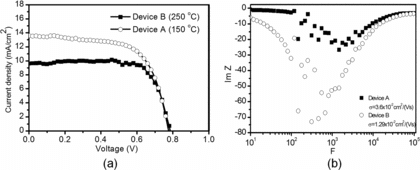
We have fabricated devices with various conditions, and here we only report the effect of drying temperature because of the strong correlation associated with the drying temperature. Device A is prepared at 150°C drying temperature, while Device B is prepared at 250°C. Other ES operating parameters (such as voltage, electrical conductivity, and flow rate) are identical for the two samples.
shows the I-V curves of devices A and B. Both devices have the same thickness (14 ± 2 μm). For device B, the short circuit current is Jsc = 9.19 mA/cm2, the open circuit voltage is Voc = 0.77 V, the fill factor is 62%, and the overall energy conversion efficiency is η = 4.4%. For device A, while the open circuit voltage is unchanged (Voc = 0.77 V), the short circuit current is boosted to Jsc = 13.58 mA/cm2, and the fill factor reaches FF = 65%. This translates to overall energy conversion efficiency of device A to η = 6.81%.
To explain the very different device performance, we measured the carrier mobility of both devices. The carrier mobility is determined through frequency dependence of imaginary part of impedance (ImZ) (Tripathi et al. 2011). First the impedance-frequency plot is obtained, and the peak frequency (where ImZ is the maximum) F is located. The carrier migration time is given by τc = 0.35τF, where τF = 1/F. Then the charge carrier mobility is obtained using μ = d2 /τ Vb, where d is the thickness of the active layer of the photoelectrode, and Vb is the applied bias voltage. From the impedance data in , the mobility is measured at 1.3 × 10⁻² cm2/(V·s) for device B and 3.6 × 10⁻² cm2/(V·s) for device A. We can connect the mobility to the micro particle morphology generated at different drying temperature. Since 150°C leads to mostly solid particles, there exists more interconnection among TiO2 nanoparticles within a micro particle. In contrast, the 250°C drying temperature results in hollow micro particles and there are less TiO2 nanoparticle interconnections that translate into significantly lower apparent carrier mobility and Jsc. Therefore, solid particles, which are generated at a carefully chosen drying temperature (∼50 K below the solvent boiling point in this work), are more desirable to achieve higher charge carrier mobility, higher short circuit current, and eventually better device performance.
4 CONCLUSIONS
We have used electrospray approach to fabricate photoelectrodes for Dye Sensitized Solar Cells using dense (40 wt.%) suspensions of TiO2 nanoparticles in ethylene glycol. Compared with previous reports on electrospray route for fabricating metal oxide photoelectrodes, the major contribution of this work is that we were able to increase the TiO2 nanoparticles concentration by up to three orders of magnitude. The electrospray of dense suspensions produces active layers with uniform overall film thickness in one simple step. Closer examination of the film reveals hierarchical nano/micro structures of multiple length scales: the film consists of micro clusters with characteristic size of ∼20 μm, and the building blocks of the clusters are 2 ± 1 μm diameter micro spheres made of 25 nm TiO2 nanoparticles. Although other existing film deposition methods (such as doctor blading and die casting) can easily handle dense suspensions, they produce homogeneous films instead of hierarchical structures demonstrated in this work. A suitable temperature range (150°C in this work) is important to ensure complete drying of suspension droplets while avoiding creation of hollow particles, because the hollow particles exhibit significantly lower carrier mobility and less power conversion efficiency. The assembled DSSC devices fabricated under 150°C reached power conversion efficiency up to 6.81%.
The high solid concentration demonstrated in this work can potentially reduce the manufacturing cost of DSSC because less energy will be wasted on evaporating and/or recycling the organic solvent. Our results illustrate the unique advantages of using ES as a manufacturing tool in DSSCs, such as atmospheric deposition, improved the morphology of the active layers, and potential for roll-to-roll deposition. We further note that the throughput of a single electrospray is relatively low (about ∼0.05 mL/h in this work), therefore, multiplexed electrosprays (MES) are indispensable in the scale up of ES deposition. Recent progress in MES (Deng et al. Citation2006, Citation2009, 2010) suggests that in principle the throughput of electrospray is scalable and, therefore, the ES of dense suspension is a feasible and potentially competitive approach for manufacturing DSSCs.
REFERENCES
- Almería, B., Deng, W., Fahmy, T.M., and Gomez, A. (2010). Controlling the Morphology of Electrospray-Generated PLGA Micro-Particles for Drug Delivery. J Colloid Interf. Sci., 343:125–133.
- Bach, U., Lupo, D., Comte, P., Moser, J.E., Weissörtel, F., Salbeck, J., et al. (1998). Solid-State Dye-Sensitized Mesoporous TiO2 Solar Cells with High Photon-to-Electron Conversion Efficiencies. Nature, 395:583–585.
- Chen, D., Huang, F., Cheng, Y.B., and Caruso, R.A. (2009). Mesoporous Anatase TiO2 Beads with High Surface Areas and Controllable Pore Sizes: A Superior Candidate for High-Performance Dye-Sensitized Solar Cells. Adv. Mater., 21:2206–2210.
- Chou, T.P., Zhang, Q., Fryxell, G.E., and G. Cao, G.Z. (2007). Hierarchically Structured ZnO Film for Dye-Sensitized Solar Cells with Enhanced Energy Conversion Efficiency. Adv. Mater., 19:2588–2592.
- Cloupeau, M., and Foch, B.P. (1990). Electrostatic Spraying of Liquids: Main Functioning Modes. J. Electrostat., 25:165–184.
- Deng, W., and Gomez, A. (2010). The Role of Electric Charge in Microdroplets Impacting on Conducting Surfaces. Phys. Fluids, 22:051703–051707.
- Deng, W., Klemic, J.F., Li, X., Reed, M., and Gomez, A. (2006). Increase of Electrospray through Put Using Multiplexed Microfabricated Sources for The Scalable Generation of Monodisperse Droplets. J. Aerosol Sci., 37:696–714.
- Deng, W., Waits, C.M., and Gomez, A. (2010). Digital Electrospray for Controlled Deposition. Rev. Sci. Instrum., 81:0351141–0351146.
- Deng, W., Waits, C.M., Morgan, B., and Gomez, A. (2009). Compact Multiplexing of Mono-Disperse Electrosprays. J. Aerosol Sci., 40:907–918.
- Ding, I.K., Kyriazi, J.M., Ha, N.L. C., Chittibabu, K.G., S.M. Zakeeruddin, S.M., and Grätzel, M. (2010). Deposition of Hole-Transport Materials in Solid-State Dye-Sensitized Solar Cells by Doctor-Blading. Org. Electron., 11:1217–1222.
- Fernández, D.L. M. (2007). The Fluid Dynamics of Taylor Cones. Annu. Rev. Fluid Mech., 39:217–243.
- Fernández, D.L. M., and Loscertales, I.G. (1994). The Current Emitted by Highly Conducting Taylor Cones. Fluid Mech., 260:155–184.
- Fujimoto, M., Kado, T., Takashima, W., Kaneto, K., and Hayase, S. (2006). Dye-Sensitized Solar Cells Fabricated by Electrospray Coating Using TiO2 Nanocrystal Dispersion Solution. J. Electrochem. Soc., 153:A826–A829.
- Ganan-Calvo, A.M., Lasheras, J.C., Davila, J., and Barrero, A. (1994). Electrostatic Spray Emitted from an Electrified Conical Meniscus. J. Aerosol Sci., 25:1121–1142.
- Grätzel, M. (2001). Photoelectrochemical Cells. Nature, 414:338–344.
- Hagfeldt, A., and Grätzel, M. (2000). Molecular Photovoltaics. Acc. Chem. Res., 33:269–277.
- Hartman, R.P. A., Borra, J.P., Brunner, D.J., Marijnissen, J.C. M., and Scarlett, B. (1999). Evolution of Electrohydrodynamic Sprays Produced in Cone-Jet Mode. A Phys. Model J. Electrostat., 47:143–170.
- Hao, S., Wu, J., Fan, L., Huang, Y., Lin, J., and Wei, Y. (2004). The Influence of Acid Treatment of TiO2 Porous Film Electrode on Photoelectric Performance of Dye-Sensitized Solar Cell. Sol. Energy, 76:745–750
- Higuera, F.J. (2003). Flow Rate and Electric Current Emitted by a Taylor Cone. Fluid Mech., 484:303–327.
- Hogan, C., and Biswas, P. (2008). Porous Film Deposition by Electrohydrodynamic Atomization of Nanoparticle Sols. Aerosol Sci. and Technol., 42(1):75–85.
- Huang, F., Chen, D., Zhang, L.X., Caruso, R.A., and Cheng, Y.B. (2010). Dual-Function Scattering Layer of Submicrometer-Sized Mesoporous TiO2 Beads for High-Efficiency Dye-Sensitized Solar Cells. Adv. Mater., 20:1301–1305.
- Hwang, D., Lee, H., Jang, S.Y., Jo, S.M., Kim, D., Seo, Y., et al. (2011). Electrospray Preparation of Hierarchically-structured Mesoporous TiO2 Spheres for Use in Highly Efficient Dye-Sensitized Solar Cells. Appl. Mater. Interfaces., 2011:2719–2725.
- Ito, S., Murakami, S.T. N., Comte, P., Liska, P., Grätzel, C.K. Nazeeruddin, M.K., et al. (2008). Fabrication of Thin Film Dye Sensitized Solar Cells with Solar to Electric Power Conversion Efficiency over 10%. Thin Solid Films., 516:4613–4619.
- Kim, Y.J., Lee, M.H., Kim, H.J., Lim, G., Choi, Y.S., Park, N.G., et al. (2009). Formation of Highly Efficient Dye-Sensitized Solar Cells by Hierarchical Pore Generation with Nanoporous TiO2 Spheres. Adv. Mater., 21:3668–3673.
- Modesto-Lopez, L., and Biswas, P. (2010). Role of the Effective Electrical Conductivity of Nanosuspensions in the Generation of TiO2 Agglomerates with Electrospray. J. Aerosol Sci., 41:790–804.
- O’Regan, B., and Grätzel, M. (1991). A Low-Cost, High-Efficiency Solar Cell Based on Dye Sensitized Colloidal TiO2 Films. Nature, 353:737–740.
- Oh, H., Kim, K., and Kim, S. (2008). Characterization of Deposition Patterns Produced by Twin-Nozzle Electrospray. J. Aerosol. Sci., 39(9):801–813.
- Papageorgiou, N., Maier, W.F., and Grätzel, M. (1997). An Iodine/Triiodide Reduction Electrocatalyst for Aqueous and Organic Media. J. Electrochem. Soc., 144:876–884.
- Peng, B., Jungmann, G., Jäger, C., Haarer, D., Schmidt, H.W., and Thelakkat, M. (2004). Systematic Investigation of The Role of Compact TiO2 Layer in Solid State Dye-Sensitized TiO2 Solar Cells. Cord. Chem. Rev., 248:1479–1489.
- Pichot, F., Pitts, J.R., and Gregg, B.A. (2000). Low-Temperature Sintering of TiO2 Colloids: Application to Flexible Dye-Sensitized Solar Cells. Langmuir5626–5630.
- Sudhagar, P., Asokan, K., Jung, J.H., Lee, Y.G., Park, S., and Kang, Y.S. (2011). Efficient Performance of Electrostatic Spray-Deposited TiO2 Blocking Layers in Dye-Sensitized Solar Cells after Swift Heavy Ion Beam Irradiation. Nanoscale Res. Lett.30–36.
- Tang, K., and Gomez, A. (1994). On the Structure of an Electrospray of Monodisperse Droplets. Phys. Fluids, 6:2317–2322.
- Taylor, G. (1964). Disintegration of Water Drops in an Electric Field. Proc. Royal Soc. London, 280:383–397
- Tripathi, D.C., Tripathi, A.K., and Mohapatra, Y.N. (2001). Mobility Determination Using Frequency Dependence of Imaginary Part of Impedance (Im Z) for Organic and Polymeric Thin Films. Appl. Phys. Lett., 98:033304–033306
- Vehring, R., Willard, R., David, F., and Ballesteros, L. (2007). Particle Formation in Spray Drying. Aerosol Sci., 38:728–746.
- Wilhelm, O., Mädler, L., and Pratsinis, S.E. (2003). Electrospray Evaporation and Deposition. J. Aerosol. Sci., 34:815–836.
- Yang, W., Lojewski, B, Wei, Y., and Deng, W. (2012). Interactions and Deposition Patterns of Multiplexed Electrosprays, J. Aerosol Sci., 46:20–33.
- Yella, A., Lee, H.W., Tsao, H.N., Chen, Y.Y., Chandiran, A.K., Nazeeruddin, M.K. E., et al. (2011). Porphyrin-Sensitized Solar Cells with Cobalt(II/III)-Based Redox Electrolyte Exceed 12 Percent Efficiency. Science, 334:629–634.
- Zhang, Y., Wu, Y.L., Xie, E., Duan, H., Han, W., and Zhao, J. (2009). A Simple Method to Prepare Uniform-Size Nanoparticle TiO2 Electrodes for Dye-Sensitized Solar Cells. J. Power Sources, 189:1256–1263.
- Zhao, X., Lojewski, B., Yang, W., Zhu, T., Mi, B., Gao, Z., et al. (2012). Electrospray as a Fabrication Tool in Organic Photovoltaics. Rev. Nanosci. Nanotechnol., 172–186.
