Abstract
Depth filter media are usually composed of multiple layers to attain optimal values of main filtration parameters such as pressure drop and particle collection efficiency (PCE). Understanding the performance of the single layers that make up the filter media can contribute to attaining these optimum values. For the purpose of this study, we have developed two samples of depth filter media, 2LM and 3LM, composed of two and three layers, respectively. Samples of the media and single layers have been prepared in flat sheet form. Filtration performance of these samples has been evaluated using a lab-scale flat sheet filter media test unit with KCl as the test aerosol. Results from these tests have been compared with those from an automated filter tester (AFT) with NaCl as the test aerosol. These media have been characterized based on filter media properties and data from the filtration performance tests and the effect of layers on filtration performance has been observed. Pressure drop data from the tests with a standard test unit and our laboratory test unit are similar, and the difference in data is attributed to high inlet concentration of KCl particles. The overall filtration performance is strongly dependent on the final layer regarding pressure drop and particle of two- and three-layer filter media. Other constituent layers can be seen as contributors to the dust-holding capacity of the filter media and can reduce the dust load for the final layer.
Copyright 2013 American Association for Aerosol Research
1. INTRODUCTION
In applications, such as gas turbine or heavy-duty compressor intake air filtration, filters are used to protect the machinery from particles contained in the surrounding air. Usually, these filters are assembled as cartridges, where the surface media are typically pleated to realize larger filtration capability and to allow low pressure drop. Recently, however, the use of depth filter media for such filter cartridges seem to become more prevalent than the use of surface filter media. The differences in filtration properties between these two types are listed in Albrecht et al. (Citation2003).
Depth filter media should fulfill the following requirements: high initial particle collection efficiency (PCE), low pressure drop, and high dust-holding capacity. These parameters are described in the existing literature (Brown Citation1993; Hutten Citation2007; Purchas and Sutherland Citation2007). Initial filtration performance parameters such as initial pressure drop and PCE are evaluated using clean samples of the filter media. These tests are usually performed using standard automated test units and are representative for filter media quality control. In our laboratory, we designed a flat sheet test unit that can be used for testing flat sheet samples of filter media.
Filter media resistance or pressure drop is usually regarded as the difference in pressure measured up- and downstream of the filter media sample. Pressure drop depends on filter media structure and thickness, and for loading tests, depends also on the collection mechanisms that govern the filtration process. In order to simulate the conditions of the environment of application, either test particles are generated from a solution (KCl or NaCl) or standard test dust is used.
Fibrous filter media have been widely researched; in many studies, filtration performance has been examined by testing the filter media as a whole and not just the single layers. Balazy and Podgorski (Citation2008) conducted theoretical and experimental work on aerosol depth filtration and reported that it was difficult to predict initial filter efficiencies by means of theoretical calculations, resulting in a mismatch with experimental results for media consisting of two layers of different fiber diameter and with different levels of homogeneity. Filtration performance of filter media has also been simulated using 3D filter models (Maze et al. Citation2008), confirming the well-known fact that fiber diameter has an effect on filter efficiency. The filtration performance and the loading characteristics of nano- and micro-fibrous nonwoven materials have been investigated using submicron aerosols (Leung and Hung Citation2008). The effect of adding nanofiber layers to substrate layers has also been investigated in Wang et al. (Citation2008). The authors have reported that the performance of microfiber filter media can be enhanced by adding thick nanofiber layers. Nanofiber solidity and the effect of adding nanofiber layers to a microfiber substrate have also been studied by Podgorski et al. (Citation2006). In Sambaer et al. (Citation2012) authors used multilayered nanofiber media for their tests and found that the sheet media made by adding of multiple layers can increase the PCE and pressure drop.
These studies limit their scope on the development of the flat sheet depth filter media made of fine nanosize fibers.
In our study, we intend to develop a multilayer structure depth filter media by combining the various single layers with different function. These layers vary in the fiber size, thickness, and manufacturing process. The proper combination of these layers in one media should result in an optimal depth filter media for application in gas turbine and compressor intake air filtration.
For this study, two samples of filter media, two layer media (2LM), and three layer media (3LM) have been developed. In order to evaluate the performance of the single layers, samples of each layer have been prepared as flat sheet samples. In our study, we focus on the filtration performance of two filter media, hereafter regarded as 2LM and 3LM, and their single layers to provide insight into the filtration properties of single layers and their effects on the filter media as a whole. By evaluating the filtration performance of the filter media samples as well as the single layers, we intend to discern to what extent the performance of the media depends on the single layers and the effect that each layer has, based on the functions they were designed for.
2 EXPERIMENTAL SECTION
The samples are investigated using the flat sheet test unit and the data are compared with those of the standard test unit Automated Filter Tester—AFT (TSI, model 8130) for the same face velocity. Since the standard test units do not provide the flexibility to vary the filtration parameters and analyze the performance of the filter media in detail, we have utilized the flat sheet test unit with KCl as the test aerosol to evaluate the fractional efficiency (FE) by measuring the pressure drop at the same time. The effects of the layers on the filtration performance of the depth filter media are evaluated by analyzing the filtration performance, initial pressure drop, and PCE for each layer individually and comparing these with the filter media, 2LM and 3LM.
Basic filtration properties such as air permeability and mean flow pore size (MFPS) are measured using standard test units. Air permeability of the media is measured using an air permeability tester (TEXTEST, model FX3300) with a sample size of 20 cm2 at a pressure of 125 Pa. MFPS is measured using a capillary flow porometer (PMI) with a sample diameter of 1.7 cm. The AFT (TSI, model 8130) is used to measure the initial filtration parameters, pressure drop, and particle penetration.
During the tests with the flat sheet test unit, because of technical limitations, the samples are tested at the following face velocities: 2LM and 3LM are tested at 1.6, 3.2, 6.4, and 9.6 m/min; the meltblown (MB1, MB2) and thermalbond layer (ThB2) are tested at 3.2, 6.4, and 9.6 m/min; and staple fiber (SF), thermalbond (ThB1), and combined SF and thermalbond (SFThB2) layers are tested at 3.2 and 6.4 m/min.
2.1 Experimental Set-Up and Procedure
The experimental set-up consists of the following functional units: an aerosol generation and diffusion drying column together with a particle charge neutralizer, a filter chamber column with pressure drop and particle sampling ports, a particle concentration measurement device, data acquisition and control units, and an air flow control unit that includes a vacuum pump and MFC controller. A schematic of the test unit is presented in .
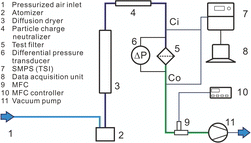
Samples of filter and layer species with diameter of 50 mm are cut and placed between two clamps, which hold the filter sample in the middle of the filter chamber column. The effective filtration size matches the diameter of 42 mm; thus, the face velocity is calculated based on this value. Particle concentration measuring ports are also placed up- and downstream of the filter species. During the tests, these two ports are alternately connected to Scanning Mobility Particle Sizer—SMPS (TSI, model 3936) to measure the inlet and outlet aerosol concentration. The particle sampling ports are made of the inner diameter 4 mm tube and are not isokinetic with the main flow due to test unit size limitations. The time difference between two measurement runs is set to approximately 2 min and the total time spent for measurement of one value of face velocity (including inlet and outlet) is 8 min. The PCE is calculated by comparing the inlet concentration (Ci) and outlet concentration (Co) using the following expression:
For FE, Co, and Ci are related to a particular particle size, and in the case of total collection efficiency, Co and Ci are related to the total amount of particles (number- or mass-based total collection efficiency) up- and downstream of the test species, respectively.
To measure the pressure drop, both ports up- and downstream of the filter media specimens are connected to a differential pressure transmitter and the values are recorded manually.
2.2 Test Particles
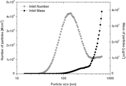
The KCl particles are generated from a 10% wt. KCl solution using the Single Jet Atomizer (TSI, model 9302). KCl crystals are dried by passing through the diffusing dryer column and are neutralized using the particle charge neutralizer. The range of particles measured by SMPS lies between 20 and 600 nm. Data for the particle size range 20–46 nm are inconsistent; therefore, particles of that particular size range are not taken into consideration. The number concentration in this range was very small causing severe particle concentration fluctuations. Particle size distribution is displayed in . The median size is around 160 nm with a standard deviation of <1.8. Particle size expressed in is related to mobility particle size measured by SMPS and data are not converted in aerodynamic particle size.
2.3 Filter Media
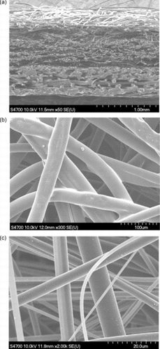
Two samples of depth filter media composed of multiple layers and single layers, which are included in the media structure, are also prepared separately as flat sheet samples. Depth filter media 2LM is made up of two functional layers: meltblown (MB, hereafter referred to as MB1 when discussed in relation to 2LM) and thermalbond (ThB1). a shows the arrangement of the layers of media 2LM with supporting layer at the top, Mb layer in the middle, and ThB1 at the bottom. Magnified SEM images of the layers ThB1 and MB1 are displayed in b and c, respectively. Filter media 3LM, displayed in a, is composed of three functional layers: meltblown (MB2), SF, and thermalbond (ThB2). Magnified SEM images of the layers MB2, SF, and ThB2 are displayed in b–d, respectively. In addition, layer SFThB2 is composed of SF, scrim, and ThB2 for the purposes of measuring the MFPS, since SF and ThB2 exhibit very low pressure drop; hence, measurement with a PMI was not possible. A summary of properties of the filter media 2LM and 3LM and single layers is displayed in .
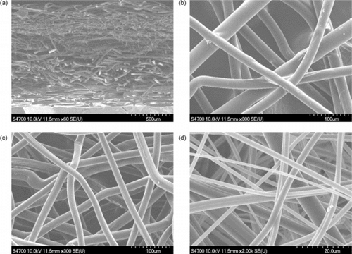
Table 1 2LM and 3LM filter media and layer properties
The depth filter media usually is composed of multiple layer structure. These layers have their own function. The first layer (ThB1 and ThB2) usually made of large fiber size and open fibrous structure is placed at the upstream of remaining layers and its function is to collect large particles. This layer should not pose a high-flow resistance. It also can serve for reducing the particle load and can contribute to filter media stiffens. Especially when the media is supposed to be a pleated filter, the stiffness is important to keep the pleat shape at certain operating pressure drop. Thermalbond layer is placed as upstream layer and its function is sort of prefilter and supporting layer of the depth filter media. Thermalbond layer fibers are made of the so called sheath-core structure. The sheath is made of low melt polymer so that the sheath will melt under temperature treatment. The fibers are then fixed to each other and represent a rigid fibrous structure. The second layer (SF) is the depth filter layer. The function of this layer is to hold large amount of dust in inner of the layer. The final layer (MB1 and MB2) is the layer responsible for removal of fine particles from air stream passing through it. This layer is usually made of small diameter fibers and low porosity. The thickness of this layer should be chosen carefully due to high pressure drop. The function of the final layer is to collect particles with high efficiency.
3 RESULTS AND DISCUSSION
3.1 Pressure Drop Characteristics
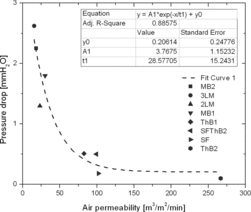
The initial pressure drop of the 2LM filter media is influenced by the pressure drop of the meltblown media, which exhibits the highest values of pressure drop of all the layers contained in the depth filter media. Due to the small fiber diameter and high-packing density, this layer exhibits low-air permeability, and therefore, as a consequence, the pressure drop is high compared to other layers which exhibit higher air permeability. This means that the pressure drop values of the filter media will vary according to the layer with the highest value. A high pressure drop indicates low-air permeability. The correlation of these two parameters is displayed in . All data are related to a face velocity of 3.2 m/min for comparison. This value of face velocity is accepted as a standard value for testing of flat sheet filter media and is widely used in other related research works and literature. Highest values of pressure drop are found for the MB layers. Both ThB layers exhibit high-air permeability and are of rigid fibrous structure with low fiber-packing density, but differ in specific weight and layer thickness. From the diagram, we can observe the following trends: for high-air permeability layers (ThB1, SF, SFThB, and ThB2), the change in air permeability does not significantly affect the pressure drop; however, small differences in air permeability significantly affect the pressure drop for low-air permeability media and layers (2LM, 3LM, MB1, and MB2). In this context, we can classify the media and layers into two groups, as shown in .
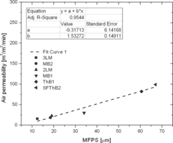
The dependency of air permeability on MFPS is displayed in . Owing to the presence of the multiple layers, 2LM and 3LM exhibit low-air permeability values and smaller MFPS. The pressure drop exhibits a linear curve dependence on the MFPS; therefore, the smaller the MFPS, the lower the air permeability and vice versa.
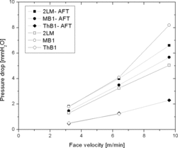
Comparison of results for pressure drop from the test with the standard TSI unit and those from the flat sheet test unit indicates some small differences (); the highest values are exhibited by the MB layer, with values of around 8 mm H2O. In the case of the standard TSI unit (data marked with AFT), 2LM exhibits the highest value of pressure drop at 6.6 mm H2O. When the same samples are measured with the flat sheet test unit, 2LM exhibits greater pressure drop than MB1. Data from the flat sheet test unit are taken from the first run, when the sample is not much affected by particle loading. Small differences in pressure drop values from the tests with standard test unit and the flat sheet test unit are seen as a consequence of higher particle concentration and the loading time, which is longer compared to the standard test unit measuring time and is set to 20 s, in accordance with the existing literature (TSI Citation2012 and TSI Citation2012a). ThB1 pressure drop values from both test units overlap.
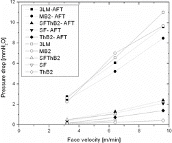
Pressure drop increases with face velocity in the case of the flat sheet test unit where the particle loading, even for a short loading time, affects the increase of pressure drop for 3LM and all layers (). Pressure drop of all layers and the media are identical at the face velocity 3.2 m/min but the difference in pressure drop values increase with the increase of face velocity. Especially for MB2 layer and the media 3LM the difference is more significant. Owing to high-air permeability, SF, SFThB2, and ThB2 exhibit low pressure drop.
3.2 Particle Collection Efficiency
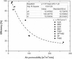
The relationship between overall collection efficiency and air permeability is shown in . The correlation follows a similar trend to that of pressure drop and air permeability. According to the results, the lower the air permeability the poorer the overall collection efficiency. The low-air permeability means that the fiber packing density is higher and the fiber size is smaller. This results in higher pressure drop values. Generally, from the theory of filtration, it is known that high pressure drop filter media collect particles with high efficiency.
When the PCE is displayed as function of particle size, it is easy to identify the efficiency of collection of particles of a specific size. MB1 exhibits even higher PCE than 2LM (), which may be related to the higher pressure drop displayed in , with a small difference in values between the standard and flat sheet test units. For particle size of the range discussed in this study, the dominant particle capture mechanism is, according to the filtration theory (Brown Citation1993; Hutten Citation2007), Brownian diffusion, and interception. Brownian diffusion is directly related to fiber size, face velocity and the fiber packing density (solidity). The finer the fiber diameter the higher is the packing density. Generally, the PCE increases with the decreasing fiber diameter as explained in a diagram by Ramskill and Anderson (Citation1951).
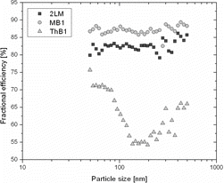
ThB1 exhibits a minimum FE for particles with a size of 150 nm. Similar behavior is reported in Maze et al. (Citation2008). Despite the large fiber diameter and less dense packing of fibers, it exhibits high-collection efficiency. This is due to the interfiber connection through melted polymer which contributes to additional decrease of void space between fibers. These results correlate with the pressure drop data displayed in , where the pressure drop values for MB1 and ThB1 do not differ much for a face velocity of 3.2 m/min, although the difference increases with an increase in face velocity.
The results indicate that ThB1 does not contribute to the increase in efficiency. Its effect can be explained by a reduction in dust load that takes place within ThB1. MB1 exhibits high-collection efficiency owing to its fine fiber structure and a particle collection mechanism that dominates in the case of the high concentrations. 2LM exhibits moderate collection efficiencies (above 80%) at low-face velocities and even lower FE for high face velocities of 6.4 and 9.6 m/min. FE decreases with an increase in face velocity and reaches maximum values at around 70% efficiency at 6.4 and 9.6 m/min.
From theory, it is known that the lower the face velocity the longer the resident time of particles inside the fibrous media and thus the higher the collection efficiency (Figure S4 in the online supplementary information [SI]).
The pressure drop and FE of MB1 are higher than those of filter media 2LM. The combination of the MB1 layer with the ThB1 layer slightly lowers pressure drop and collection efficiency. This can be explained by the fact that when the MB layer acts as a filter media alone, it experiences the full particle load directly and cake formation is eminent. As a result, the pressure drop increases with the consequence of higher collection efficiency. Thus, the difference in pressure drop and collection efficiency between MB1 and 2LM can be explained by the fact that the particle load is distributed throughout the layer ThB1 and the fine particles penetrate through easily.
3LM exhibits high-collection efficiency, and this is attributed to the high-efficiency layer of MB fibers. Owing to the layer structure expressed in air permeability, the layers SF and ThB2 exhibit low FE. For 3LM, we can confirm a similar tendency, where the performance of the filter media is strongly dependent on the performance of the MB layer, as shown in . As it is suggested in the existing literature (Brown Citation1993; Hutten Citation2007; Purchas and Sutherland Citation2007), FE decreases with an increase in face velocity.
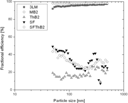
In particular, the collection efficiency of fine particles (smaller than 200 nm) is strongly affected by increases in the face velocity (Figure S5 [SI]). For less densely packed layers like ThB and SF, particle loading does not affect the increase of pressure drop owing to the fiber diameter, less densely packed fibrous structure, and layer thickness. These layers can contribute to dust accumulation inside the filter media. Large fiber diameters can contribute to collection of particles larger than the most penetrating particle size (MPPS), regarded as the size of 0.3μm. For particles larger than MPPS, the dominant particle collection mechanisms are the interception and the inertial impaction. Interception is related to the parameter defined as the particle to fiber size ratio. Inertial impaction is defined by the Stokes number. The initial impaction collection mechanism is more dominant for large particle size and high velocity (Brown Citation1993; Lee and Mukund Citation2001).
The tendency for pressure drop to increase is less pronounced for 3LM, even though this media includes MB, which exhibits higher pressure drop, as the final layer. This phenomenon is due to the particle-holding capacity of SF and screening effect of the ThB2 layer, which in turn reduces the particle load facing the MB layer.
The layers SF and ThB2 exhibit low PCE, and results indicate that combining two low-PCE layers improves PCE slightly. In the literature (Brown Citation1993), adding of layers is suggested as a means to improve the performance of filter media. This might be the case for adding of layers with same properties. In our case, for 2LM, we cannot confirm that addition of layers can lead to addition of single layer efficiencies. Even though ThB1 exhibits much higher PCE than ThB2, adding ThB1 does not significantly affect the PCE of 2LM. Furthermore, adding the layers SF and ThB2 does not seem to improve the performance of 3LM in terms of pressure drop and PCE.
4 CONCLUSIONS
Both 2LM and 3LM exhibit filtration performance that can mainly be attributed to the MB layer. Also, the filtration performance of the MB layer evaluated in this study does not necessarily represent the true performance attributed to the high inlet particle concentration and its effects on pressure drop, especially for the efficient layer MB2. Layers ThB1, ThB2, and SF have less densely packed fibers and low PCE but contribute to uniform distribution of particles and low pressure drop owing to the high-air permeability. SF is designed to increase particle-holding capacity.
Filter media 3LM presents a good example of depth filter media. Further development is required to extend the capacity of the media by adding a more open-structure middle layer without extensive increase of pressure drop. With the aim of evaluating the dust-holding capacity, testing of the media with standard fine test dust and evaluation of the performance of the media when assembled in a cartridge should be conducted in order to evaluate the overall filtration performance of the media and the cartridge. This should be a subject of future work.
Supplemental_Information.zip
Download Zip (570.4 KB)REFERENCES
- Albrecht, W., Fuchs, H., and Kittelmann, W. (2003). Nonwoven Fabrics: Raw Materials, Manufacture, Applications, Characteristics, Testing Processes. WILEY-VCH Verlag, Weinheim.
- Balazy, A., and Podgorski, A. (2008). Verification of the Classical Theory of Aerosol Depth Filtration. Chem. Process Eng., 29:361–374.
- Brown, R.C. (1993). Air Filtration: An integrated Approach to the Theory and Applications of Fibrous Filters. Pergamon Press, Oxford.
- Hutten, I.M. (2007). Handbook of Nonwoven Filter Media. Elsevier, Oxford.
- Lee, K.W., and Mukund, R. (2001). Filter collection, in Aerosol Measurement: Principles, Techniques and Applications,2nd Ed. Wiley-Interscience.
- Leung, L.W., and Hung, CH. (2008). Investigation on Pressure Drop Evolution of Fibrous Filter Operating in Aerodynamic Slip Regime Under Continuous Loading of Sub-Micron Aerosols. Separ. Purif. Technol., 63:691–700.
- Maze, B., Tafreshi, H.V., and Pourdeyhimi, B. (2008). Case Studies of Air Filtration at Microscales: Micro-and Nanofiber Media. J. Eng. Fibers and Fabrics, 3(2):7–12.
- Podgorski, A., Balazy, A., and Gradon, L. (2006). Application of Nanofibers to Improve the Filtration Efficiency of the Most Penetrating Aerosol Particles in Fibrous Filters. Chem. Eng. Sci., 61:6804–6815.
- Purchas, D.B., and Sutherland, K. (2007). Handbook of Filter Media. Elsevier, Oxford.
- Ramskill, E.A., and Anderson, W.L. (1951). The Inertial Mechanism in the Mechanical Filtration of Aerosols. J. Colloid Sci., 6:416–428.
- Sambaer, W., Zatloukal, M., and Kimmer, D. (2012). 3D Air Filtration Modelling of Nanofiber Based Filters in the Ultrafine Particle Size. Chem. Eng. Sci., 82:299–311.
- TSI (2012). Filter Testers for Air Filter and Media Efficiency Measurement. Automated Filter Testers. http://www.tsi.com/uploadedFiles/_Site_Root/Products/Literature/Spec_Sheets/8127–8130_1931214_USA_web.pdf (accessed on 1st February 2013).
- TSI (2012a). Automated Filter Testing. CERTITEST Automated Filter Testers Model 8127 8130. . http://www.tsi.com/uploadedFiles/_Site_Root/Products/Literature/Brochures/Filter%20Testers_5001174-US.pdf (accessed on 1st February 2013).
- Wang, J., Kim, S.C., and Pui, D.Y.H. (2008). Investigation of Figure of Merit for Filters with Single Nanofiber Layer on a Substrate. J. Aerosol Sci. 39:323–334.
