Abstract
The effect of an orifice on the collection efficiency and wall loss of a slit virtual impactor was investigated both numerically and experimentally. The ratios of the collection nozzle width (Wc ), distance between acceleration nozzle and collection nozzle (S), length of acceleration nozzle (T), inlet width (D), and nozzle span (l) to the acceleration nozzle width (Wa ) were fixed at Wc /Wa = 1.4, S/Wa = 1.5, T/Wa = 1.1, D/Wa = 6, and l/Wa = 10, respectively. The minor-to-total flow ratio was set to 0.1 in laminar flow regime. The collection efficiency and wall loss of the slit virtual impactor were found to be characterized by the square root of the Stokes number. For the slit virtual impactor without an orifice, the square root of the Stokes number corresponding to the cut-off diameter was determined to be (Stk50)1/2 = 0.77 and the maximum wall loss at the collection nozzle reached 30% or 40%. When an orifice having the same width as the acceleration nozzle was placed upstream of the acceleration nozzle at a distance of 20Wa , the value of (Stk50)1/2 decreased to 0.68 and the wall loss at the collection nozzle decreased below 5%.
Copyright 2014 American Association for Aerosol Research
1. INTRODUCTION
Inertial impactors, which are widely used for sampling atmospheric particles, have the advantages of simple configuration and easy operation. Many studies on the performance of inertial impactors have been conducted by changing geometric parameters and operation conditions, such as the nozzle width, nozzle-to-plate distance, nozzle throat length, and aerosol flow rate (Marple and Liu Citation1974; Rader and Marple Citation1985; Huang and Tsai Citation2002; Grinshpun et al. Citation2005). However, the presence of impaction plates in inertial impactors has led to the problems of particle bounce and overloading of the impaction plate. Numerous studies have been conducted to solve these problems. Rao and Whitby (Citation1978) reduced the particle bounce by coating the impaction plate with oil or substituting a glass fiber filter for the impaction plate. Tsai and Cheng (Citation1995) used impaction plates of various shapes to decrease the particle bounce. Kim et al. (Citation2013) employed impaction plates of elliptical concave curvature and reduced the particle bounce.
TABLE 1 Dimensions and operation conditions of the slit virtual impactors tested in this study, with Wc /Wa = 1.4, S/Wa = 1.5, T/Wa = 1.1, d/Wa = 1, D/Wa = 6, l/Wa = 10, L/Wa = 4∼36, and r = 0.1
The problems of particle bounce and overloading can also be overcome by using virtual impactors. Hounam and Sherwood (Citation1965) invented a virtual impactor with a collection nozzle instead of an impaction plate. As do plate impactors, virtual impactors use inertia to separate particles from an aerosol stream. In other words, particles with lower inertia mainly follow the major flow going through the outlet in the direction perpendicular to the acceleration nozzle, whereas particles with higher inertia pass through the collection nozzle with the minor flow. Hassan et al. (Citation1979) employed a numerical method to investigate the performance of a round nozzle virtual impactor. Marple and Chien (Citation1980) conducted a theoretical study on the effects of various parameters, such as the Reynolds number and minor-to-total flow ratio, on the collection efficiency of a round nozzle virtual impactor. In a virtual impactor, when particles turn toward the major-flow-outlet in the space between the acceleration nozzle and collection nozzle, some may collide with the collection nozzle and are lost. Therefore, in assessing the performance of a virtual impactor, the wall loss at the collection nozzle is also an essential factor to consider along with the collection efficiency. Accordingly, many studies have been conducted to investigate the wall loss in virtual impactors. Chen and Yeh (Citation1987) performed a parametric study to reduce wall loss and enhance the separation characteristics of an improved virtual impactor. Loo and Cork (Citation1988) suggested proper design parameters for a round virtual impactor to produce high separation efficiency and low wall loss. Ding and Koutrakis (Citation2000) conducted an experimental study on a slit virtual impactor to investigate the effects of the Reynolds number, minor-to-total flow ratio, and ratio of collection nozzle width to acceleration nozzle width. They concluded that the principles of physical design parameters for round nozzle virtual impactors were applicable to slit nozzle virtual impactors.
Although the effects of the dimensions and parameters on the collection efficiency and wall loss of the virtual impactor have been investigated in many studies, there have been few studies on virtual impactors with a specific device, such as an orifice, employed to enhance collection efficiency and reduce wall loss. Therefore, the objective of this study is to investigate the collection efficiency and wall loss of the slit virtual impactor with an orifice installed upstream of the acceleration nozzle.
2. NUMERICAL
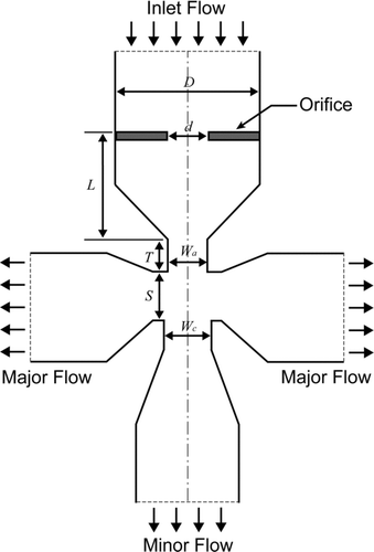
shows the cross-sectional view of a slit virtual impactor with an orifice. The widths of the acceleration nozzle and the collection nozzle were denoted as Wa and Wc , respectively. The distance between the two nozzles was denoted as S, the length of the acceleration nozzle as T, the width of the orifice as d, the width of the inlet as D, the distance between the orifice and the acceleration nozzle as L, and the span of the slit nozzle as l. lists the values of the width of the acceleration nozzle, flow rate through the acceleration nozzle (Q), and corresponding Reynolds number (Re), which were tested in this study. In general, the performance of a slit virtual impactor is affected by its dimensions (Ding and Koutrakis Citation2000; Kim et al. Citation2004). In the present study, the geometric dimensions were determined as multiples of the width of the acceleration nozzle, that is, Wc /Wa = 1.4, S/Wa = 1.5, T/Wa = 1.1, d/Wa = 1, and D/Wa = 6, based on the studies of Loo and Cork (Citation1988) and Ding and Koutrakis (Citation2000). The ratio L/Wa was varied from 4 to 36. To ensure that the two-dimensional analysis of the flow was applicable, the cross section of the nozzle was determined so that the span-to-width ratio was l/Wa = 10.
A computational fluid dynamics (CFD) code, FLUENT v13, was used to simulate the flow in the slit virtual impactor. The specified number of computational cells ranged from about 10,000 to 70,000 depending on the acceleration nozzle width. The airflow was assumed to be two-dimensional, steady, incompressible, and laminar. The Reynolds number (Re) at the acceleration nozzle, which ranged approximately from 500 to 2000, was calculated as
The particle trajectory was calculated using the discrete phase model (DPM), which was based on the Lagrangian particle tracking approach and provided in the FLUENT code. The particles were assumed to be affected by Brownian diffusion, gravitational settling, and Stokes’ drag with slip correction. A plug flow velocity profile and a uniform particle number concentration were assumed at the inlet of the slit virtual impactor. Particles of 1050 kg/m3 in density were initially placed at the impactor inlet with a constant spacing and injected with the same velocity as the inlet flow velocity. Once the particles hit the walls, they were assumed to be trapped without reflection or reentry. The collection efficiency (η) and wall loss (WL) were numerically determined as
3. EXPERIMENTAL
The Stokes number (Stk) was calculated as
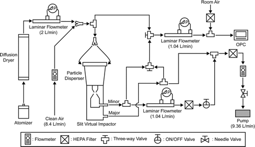
shows a schematic of the experimental setup for measuring η and WL of the slit virtual impactor. Polystyrene latex (PSL, Thermo Scientific) spheres were used, and the tested particle sizes were 1.0, 1.6, 2.0, 2.5, 3.0, and 4.0 μm. The PSL particles were aerosolized using an atomizer and dried in a diffusion dryer at a flow rate of 2 L/min. The dried PSL aerosol was diluted with clean air at a flow rate of 8.4 L/min. Then, the aerosol was introduced at a flow rate of 10.4 L/min to the aerosol particle disperser, the design of which can be found in Kim et al. (Citation2013), to uniformly disperse the particles upstream of the slit virtual impactor. The minor flow rate was 1.04 L/min and the major flow rate was 9.36 L/min. An optical particle counter (OPC, HCT model PS-3030) with 10 size bins was used to measure the particle number concentration at the impactor inlet, minor flow outlet, or major flow outlet. Because the suction flow rate of the OPC was 2.83 L/min, room air filtered at a flow rate of 1.79 L/min was added to the aerosol sampled at a flow rate of 1.04 L/min. The values of η and WL were experimentally determined as
4. RESULTS AND DISCUSSION
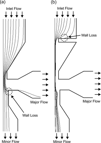
shows the simulated particle trajectories in the slit virtual impactor without or with an orifice, when Wa = 1.2 mm and L = 4.8 mm. Without the orifice (), some particles accelerated in the slit nozzle could collide with the collection nozzle wall while turning toward the major flow outlet. On the other hand, with an orifice installed (), some particles that were found to collect on the collection nozzle wall without the orifice were focused toward the centerline while passing through the orifice, as in aerodynamic lens systems (Wang and McMurry Citation2006), and therefore followed the minor flow without being trapped on the collection nozzle wall. Thus, the orifice reduced the wall loss on the collection nozzle and enhanced the collection efficiency.
shows a comparison of numerical and experimental data for η and WL. The flow rate of the aerosol introduced to the slit virtual impactor was 10.4 L/min. The minor-to-total flow ratio was 0.1. The dimensions of the slit virtual impactor were fixed at Wa = 1 mm, Wc = 1.4 mm, S = 1.5 mm, T = 1.1 mm, d = 1 mm, D = 6 mm, and l = 10 mm. When the orifice was used, the distance between the orifice and the acceleration nozzle, L, was varied (4, 12, 20, 28, and 36 mm). In , the lines represent the numerical results, and the symbols with error bars indicate the experimental data. Overall, the numerical results agreed very well with the experimental data. A curve-fitting procedure was employed to estimate the cut-off diameters from the experimental or numerical data. In the case without the orifice (), the cut-off diameters obtained by simulation and experiment were approximately 2.3 μm. The wall loss at the collection nozzle was severe for particle sizes similar to the cut-off diameter, and reached a maximum of about 40%. With the orifice, the cut-off diameter became lower than that without the orifice. When L was changed from 4 to 36 mm, the cut-off diameters determined by experiment or simulation were between 1.9 and 2.1 μm (); moreover, any effect of L was undetectable because of the small variation in cut-off diameter. For the slit virtual impactor with the orifice, the numerically predicted wall loss was less than 5% for particle sizes smaller than or similar to the cut-off size. However, as the particle size became larger than the cut-off size, the wall loss was anticipated to increase gradually, mainly owing to particle loss on the orifice plate ().
FIG. 4 Comparison of numerical and experimental data for collection efficiency and wall loss of the slit virtual impactor: (a) without orifice; with orifice where (b) L = 4 mm, (c) L = 12 mm, (d) L = 20 mm, (e) L = 28 mm, and (f) L = 36 mm.
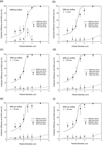
FIG. 5 Numerically obtained collection efficiencies and wall losses of the slit virtual impactors with various nozzle sizes as a function of the square root of the Stokes number: (a) without orifice; (b) with orifice, L = 20Wa .
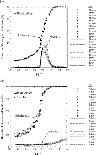
FIG. 6 Numerically obtained collection efficiency and wall loss of the slit virtual impactor without or with orifice: (a) PM1 nozzle; (b) PM2.5 nozzle; (c) PM10 nozzle.

Because the effect of L on the collection efficiency appeared to be saturated when L ranged between 4 and 36 mm, further simulations were performed by setting the distance between the orifice and the acceleration nozzle to L = 20Wa . The width of the acceleration nozzle was varied from 0.8 to 5 mm, and other geometric parameters were set to Wc /Wa = 1.4, S/Wa = 1.5, T/Wa = 1.1, d/Wa = 1, D/Wa = 6, and l/Wa = 10. The total aerosol flow rate (Q) was set as enumerated in , and the Reynolds number ranged approximately from 500 to 1600. The minor-to-total flow ratio was fixed at r = 0.1. shows the numerically obtained values of η and WL for the slit virtual impactors as a function of the square root of the Stokes number (i.e., Stk1/2). shows the η and WL for the case without the orifice, and shows those for the case with the orifice. Both η and WL of different slit virtual impactors appeared to fall on one curve, indicating that the performance of the slit virtual impactor without or with the orifice can be characterized using Stk1/2. When no orifice was used, the value of (Stk50)1/2 was determined to be 0.77. By installing the orifice upstream of the acceleration nozzle with L = 20Wa , the value of (Stk50)1/2 decreased to 0.68, that is, by about 12%. The wall loss in the slit virtual impactor for particle sizes similar to the cut-off diameter increased to about 30% or 40% without the orifice, whereas it appeared to be lower than 5% with the orifice. However, WL was estimated to increase as the particle size further increased, mainly owing to particle loss on the orifice plate ().
shows the numerically calculated values of η and WL for the slit virtual impactors, designed as PM1, PM2.5, and PM10 collectors, by using 0.77 as the value of (Stk50)1/2. In other words, the acceleration nozzle widths (Wa ) of the PM1, PM2.5, and PM10 slit virtual impactors were 0.307, 1.04, and 5.76 mm, respectively. The total aerosol flow rates were determined to yield Reynolds numbers of 500, 1000, and 2000 for the virtual impactors PM1, PM2.5, and PM10, respectively. Without the orifice, the cut-off diameters for the slit virtual impactors were predicted to be 1.04, 2.56, and 10.16 μm, respectively, and the particle sizes for maximum wall loss were 1.1, 2.6, and 11 μm, corresponding to Stk1/2 values of 0.84, 0.80, and 0.85, respectively. When the orifice was used with L = 20Wa , the cut-off diameters were anticipated to be 0.89, 2.13, and 8.91 μm, for impactors PM1, PM2.5, and PM10, respectively. The (Stk50)1/2 values calculated from the reduced cut-off diameters agreed well with the value of 0.68, with an error of less than 3%.
5. CONCLUSION
A numerical and experimental study on slit virtual impactors was performed to evaluate the effects of installing an orifice with the same width as that of the acceleration nozzle. By comparing numerical and experimental data on collection efficiency and wall loss, the simulation approach employed in this study was shown to correctly predict the performance of the slit virtual impactor in the laminar flow regime. With fixed geometric parameter ratios (Wc /Wa = 1.4, S/Wa = 1.5, T/Wa = 1.1, D/Wa = 6, and l/Wa = 10) and operation conditions (r = 0.1), the square root of the Stokes number corresponding to the cut-off diameter, that is, (Stk50)1/2, was determined to be 0.77 for the silt virtual impactor without an orifice. When an orifice with d/Wa = 1 and L/Wa = 20 was placed upstream of the acceleration nozzle, the value of (Stk50)1/2 decreased to 0.68. The orifice was beneficial in reducing both the cut-off diameter of the slit virtual impactor and wall loss at the collection nozzle. Further studies will be required to lower the particle loss on the orifice plate installed upstream of acceleration nozzle.
Acknowledgments
This research was supported by the Korea Ministry of Environment as “The Eco-Innovation Project.”
REFERENCES
- Chen , B. T. and Yeh , H. C. 1987 . An Improved Virtual Impactor—Design and Performance . J. Aerosol Sci. , 18 ( 2 ) : 203 – 214 .
- Ding , Y. and Koutrakis , P. 2000 . Development of a Dichotomous Slit Nozzle Virtual Impactor . J. Aerosol Sci. , 31 : 1421 – 1431 .
- Grinshpun , S. A. , Mainelis , G. , Trunov , M. , Górny , R. L. , Sivasubramani , S. K. Adhikari , A. 2005 . Collection of Airborne Spores by Circular Single-Stage Impactors with Small Jet-to-Plate Distance . J. Aerosol Sci. , 36 : 575 – 591 .
- Hassan , Y. A. , Jones , B. G. and Yule , T. J. 1979 . An Analytical Study of Virtual Impactor Aerosol Separators . Trans. Am. Nuclear Soc. , 33 : 182 – 184 .
- Hounam , R. F. and Sherwood , R. J. 1965 . The Cascade Centripeter: A Device for Determining the Concentration and Size Distribution of Aerosols . Am. Ind. Hyg. Assoc. J. , 26 : 122 – 131 .
- Huang , C. H. and Tsai , C. J. 2002 . Influence of Impaction Plate Diameter and Particle Density on the Collection Efficiency of Round-Nozzle Inertial Impactors . Aerosol Sci. Technol. , 36 : 714 – 720 .
- Kim , T. K. , Seshadri , S. , Kihm , K. D. , Phares , D. J. and Mclntyre , P. M. 2004 . Visualization of Defect Particle Transmission to the Major Flow of a Slit Virtual Impactor . Aerosol Sci. Technol. , 38 : 870 – 880 .
- Kim , W. G. , Yook , S. J. and Ahn , K. H. 2013 . Collection Efficiency of Rectangular Slit-Nozzle Inertial Impactors with Impaction Plates of Elliptical Concave Curvature . Aerosol Sci. Technol. , 47 : 99 – 105 .
- Loo , B. W. and Cork , C. P. 1988 . Development of High Efficiency Virtual Impactors . Aerosol Sci. Technol. , 9 ( 3 ) : 167 – 176 .
- Marple , V. A. and Chien , C. M. 1980 . Virtual Impactors: A Theoretical Study . Environ. Sci. Technol. , 14 : 976 – 985 .
- Marple , V. A. and Liu , B. Y. H. 1974 . Characteristics of Laminar Jet Impactors . Environ. Sci. Technol. , 8 : 648 – 654 .
- Rader , D. J. and Marple , V. A. 1985 . Effect of Ultra-Stokesian Drag and Particle Interception on Impaction Characteristics . Aerosol Sci. Technol. , 4 : 141 – 156 .
- Rao , A. K. and Whitby , K. T. 1978 . Non-Ideal Collection Characteristics of Inertial Impactors-I. Single-Stage Impactors and Solid Particles . J. Aerosol Sci. , 9 : 77 – 86 .
- Tsai , C. J. and Cheng , Y. H. 1995 . Solid Particle Collection Characteristics on Impaction Surfaces of Different Designs . Aerosol Sci. Technol. , 23 : 96 – 106 .
- Wang , X. and McMurry , P. H. 2006 . A Design Tool for Aerodynamic Lens Systems . Aerosol Sci. Technol. , 40 : 320 – 334 .

