Abstract
The fluid mechanics of high-frequency oscillatory ventilation (HFOV) for gas transport in the pulmonary region of the human lungs have been thoroughly studied by different methods. The major concept of HFOV adaptation is to push gas into further generation of the bronchial tree, with adequate gas mixing and small tidal volume. However, particle transport and deposition under HFOV is a rarely studied case where different mechanisms, compared to the mechanisms of gas transport, may associate. The target of this study is to numerically compare the efficiency of particle drug deposition under HFOV to normal breathing (NB) and to further clarify the mechanisms of particle transport and deposition under oscillating flows. A fully Eulerian computational fluid particles dynamic (CFPD) model is used for studying the transport and deposition of several sizes of inertia particles, under different transient flow conditions, inside a single physiologically realistic bifurcation created by generations G3–G4 of the human lung. An insight into the particle dynamics under high-frequency oscillating flow fields is given and the results showed that the highly oscillating field (HFOV) displayed stronger secondary flows, thinner boundary layers, and strong counter flow that accumulate and deposit particles further than a lower frequency oscillatory field (NB).
Copyright 2014 American Association for Aerosol Research
INTRODUCTION
High-frequency oscillatory ventilation (HFOV) is a technique of mechanical ventilation assisting or replacing spontaneous breathing, with major application in the adequate ventilation of neonates. HFOV is characterized by high-oscillation frequency (5–50 Hz), small tidal volumes, and in contrast with other mechanical ventilation techniques, uses reciprocating pumps or diaphragms in order to produce mechanically active inhalation and exhalation phases.
HFOV is commonly used for therapy of pulmonary diseases such as acute lung injury (ALI) and acute respiratory distress syndrome (ARDS) in adults and air leaks, such as pulmonary interstitial emphysema (PIE) and Bronchiolo–Alveolar injury in neonates (Clark et al. Citation1986; The Acute Respiratory Distress Syndrome Network Citation2000; Derdak et al. Citation2002).
Gas Transport Through HFOV
The mechanics of HFOV for gas transport in the pulmonary region of the human lungs have been studied experimentally, numerically and in theoretical basis in order to clarify its physiology. The major concept of HFOV is the increase of diffusion and the enhancement of the longitudinal gas transport through a forced diffusion mechanism that conclude to push gas into further generation of the bronchial tree, with adequate gas mixing and small tidal volume at the same time.
Lunkenheimer et al. (Citation1972) introduced HFOV as an improved version of other high-frequency ventilation methods. Theoretical (WatsonCitation1983) and experimental findings (Joshi et al. Citation1983) proved that in oscillatory forced flows the longitudinal flux of a gas is augmented by the increase of the oscillation frequency. Fredberg et al. (Citation1987) assessed factors influencing the mechanical performance of high-frequency ventilators under controlled conditions and noted that the dominant mechanisms of gas transport during HFOV are longitudinal (or Taylor) dispersion and molecular diffusion. Krishnan and Brower (Citation2010) developed a review study and concluded that HFOV treatment is superior than conventional mechanical ventilation (CV) and should be considered promising but experimental mode of ventilation for the treatment of plenty lung diseases. Heraty et al. (Citation2008) experimentally investigated the flow field during HFOV using particle image velocimetry on realistic and idealized bifurcation cast models in order to understand localized fluid dynamics mechanisms and concluded that the increase of oscillation frequency will increase the duration of the reverse flow near the walls (counter flow effect). The same study also highlighted the importance of secondary flows, flows at different directions than the primary flow, and recirculation in the HFOV flow field.
Hirahara et al. (Citation2011) performed a parametric numerical study of the HFOV driven flow in a geometrically symmetric dichotomous respiratory channel and provided comprehensive information for the gas flow, specifically noting the longitudinal gas redistribution characterized by the incoming central flow and the outgoing near wall flow. Zhang et al. (2002) performed a computational study for the air and particle flow under normal breathing (NB) and HFOV conditions inside a sequentially branching lung model. This study provided detailed description for the flow and particle transport mechanisms under NB conditions and plenty information for the fluid flow under HFOV. However, no information about particle transfer under HFOV was presented. Choi et al. (Citation2010) studied high-frequency oscillatory flow under consecutively more complex geometries (straight tube, single bifurcation tube model, and computed tomography based human airway model) using CFD methods and concluded that counter flow phenomenon enhances gas mixing in combination with geometrical complexity.
Scholz et al. (Citation2011) developed a comparative simulation combining Magnetic Resonance Imaging with contrast gases with computational fluid dynamics (CFD) in order to further clarify the mechanisms of gas transport during HFOV and concluded that experimental investigations through the use of MRI with the combination of CFD models may provide us with a clear idea of the gas transport mechanism.
Particle Transport and Deposition Through HFOV
Pulmonary delivery of inhaled aerosol drugs under HFOV is a highly interesting subject. However, aerosol deposition assessment under HFOV is a rarely studied case due to the difficulty of in vivo measurements and ethical concerns in conducting studies in neonates (Sood et al. Citation2010). Nevertheless, some experimental studies, available at the literature, examine the ability of drug delivery during HFOV.
Sood et al. (Citation2010) studied pulmonary aerosol delivery during HFOV in neonatal pigs with a simplified method that cannot provide details for the deposition or transport mechanisms of the particles. Briant and Lippmann (Citation1992) measured the particle transport through a cast, representing a part of the lung, during HFOV. Different carrier gases and different oscillating frequencies were used and the conclusion was that particle transport was faster in gases of higher kinematic viscosity and particle deposition is expected to increase with the oscillating frequency at high frequency situations (>2 Hz). Garner et al. (Citation2000) examined albuterol transfer by metered-dose inhaler in a high-frequency oscillatory ventilation model and concluded that albuterol transfer under that model would be problematic due to the high particle deposition on the endotracheal tube of the setup. Alzahrani (Citation2010) compared albuterol delivery under HFOV, and CV by using an experimental setup with a pressurized meter dose inhaler (pMDI) and an adult cast lung model with different compliance levels. The conclusion was that albuterol deposition was significant higher under HFOV.
Motivation for the development of our study is the fact that different mechanisms take part in particle transport and deposition, during HFOV, compared to the mechanisms of gas transport. The enhancement of the longitudinal gas transport through a forced diffusion mechanism that pushes gases into further generation of the bronchial tree may not function similar when it comes to particles. Particle inertia and wall deposition enforced by secondary flows and counter flow may play a considerable role that will lead us to different results.
The current study is a computational simulation of transport and deposition of inertial particles, under HFOV and NB conditions, inside a physiologically realistic bifurcation of the 3rd and 4th lung generation (G3–G4). The computational simulation is a fully Eulerian approach, for both air and particle phases. The Eulerian approach offers significant advantages over the frequently chosen Lagrangian approach (Pilou et al. Citation2011). Initially, it may be used for small particle diameters where the Lagrangian approach becomes highly demanding in terms of numerical implementation. Furthermore, the Eulerian model is more accurate than passive tracer (Lagrangian) models as it can take into account simultaneous diffusive and inertial particle transport. The advantages of the Eulerian approach combined with a particle transport analysis that incorporates particle inertia and diffusion at the same time, provided us with a powerful computational fluid particles dynamic (CFPD) model. This CFPD model can give insight into the particle dynamics under high-frequency oscillating flows.
In conclusion, the overall target of this study is to numerically compare the efficiency of aerosol drug deposition under HFOV to NB and to further clarify the mechanisms of particle transport and deposition under oscillating flows.
MODEL DESCRIPTION
A validated and computationally efficient fully Eulerian (fluid and particles) model that is previously used in other CFPD simulations was further developed in order to provide a better understanding of the particle transport and deposition mechanisms under oscillatory flow fields. The numerical simulation of the airflow field is carried out by the commercial software Ansys CFX®. The aerosol particle dynamics simulation is carried out using an in-house particle dynamics code, based on an Eulerian description of the particles general dynamic equation. Due to the small size of the particles, the influence of the particulate phase on the air flow field is considered negligible (one-way coupling). The geometry of the study is a physiologically realistic bifurcation based on the geometrical characteristics of the 3rd and 4th lung generations (G3–G4) bifurcation.
The particles are jetted continuously during the HFOV and NB operation and the particle concentration and deposition, is calculated during several time periods and in total. The numerical experiment simulated 12 s of real time. Nevertheless, the fluid and particle flow developed a periodic symmetry over time after the first 4 periods, namely fluid and particle fields are continuously repeated for every time period. Therefore, the results may be extrapolated to a future time snapshot. The aerosol particles are assumed to be spherical with diameter ranging from 1 nm to 10 μm.
Continuous Phase
For the calculation of the fluid flow fields the incompressible time dependent Navier–Stokes equations are solved by the finite-volume method. EquationEquation (1) gives the mass continuity equation for the incompressible flow while Equation (2) gives the momentum conservation for a time dependent case, where τ is the stress tensor, ![]() is the fluid velocity and p the pressure of the fluid.
is the fluid velocity and p the pressure of the fluid.
Air was simulated to be incompressible, justified due to the low flow velocities in the cases under study. Air density was taken equal to ρf = 1.183 kg/m3 and the kinematic viscosity equal to νf = 15.68 10−6 m2/s. The advection terms discretization scheme was set to Ansys CFX® high-resolution scheme.
The inlet velocity profile is assumed to be a sinusoidal profile with frequency equal to 16 Hz for the HFOV case and equal to 0.25 Hz for the NB case. The peak Reynolds number was set equal to 1250 for both cases based on velocity results of previous studies (Zhang et al. 2002).
Dispersed Phase
The aerosol particle dynamics simulation model is based on an in-house particle dynamics code developed for studying particle transport and deposition during internal flows (Pilou et al. Citation2011). The model is based on an Eulerian description of the particles general dynamic EquationEquation (3),
The previous version of the model was based on a description of the particles general dynamic EquationEquation (3) with focus on the transport of a population of particles and the assumption of the internal processes (growth, coagulation) absence. Based on that remarks, the GDE becomes EquationEquation (4) known as particle transport equation (P.T.E.)
Following the same methodology and assumptions as they are described in the previously employed steady state model (Pilou et al. Citation2011) (dispersed phase behaves as an ideal gas), the calculation of the particle velocity expanded by the contribution of the unsteady flow effects is done. The equation for the calculation of the particle velocity ![]() at transient cases becomes EquationEquation (5),
at transient cases becomes EquationEquation (5),
Older studies concluded to similar equations for the calculation of particle velocity. Maxey (Citation1987) defined a similar particle velocity equation utilizing a first order approach based on small particle relaxation time, later Druzhinin (Citation1995) extend the particle velocity expression to a second order approximation. Ferry and Balachandar (Citation2001) utilized this expression to a fully Eulerian particle transport model. The characteristic of the aforementioned studies is the calculation of particle velocity with the absence of the diffusive term taking into account only the convection particle velocity. Additional literature review about particle transport and deposition modeling may be found in the work of Pilou et al. (Citation2011) and Hoffman (Citation2011).
The tube diameter dt , the peak fluid velocity at the tube inlet Uo and the mean particle mass concentration at the tube inlet co , are thus chosen to render EquationEquation (5) dimensionless. The following relationships hold for the various dimensionless quantities (noted with an ′):
Thus EquationEquation (5) may be written in dimensionless form as EquationEquation (6),
For the time, discretization of the concentration of the particles a forward Euler scheme was used. Namely, the time derivative for the particle concentration was given by EquationEquation (7).
The particle transport equation is then numerically solved by the use of finite volume method.
Model Validation
Inertia and Gravity Term Validation
The incorporation of inertia and external forces term in the proposed model has been validated through comparison with experimental and other computational data on the calculation of the deposition fraction of aerosols (Pilou et al. Citation2011). Additionally, the deposition fraction was compared, with evaluated results, against experimental findings at cases where extra forces are present (Pilou et al. Citation2013). Based on those previous simulations the inertia term of the model is considered elaborated enough to simulate inertial particle transfer and deposition.
Transient Term Validation
The model is further developed in the current study for the simulation of unsteady flows and the validity of the additional transient term of EquationEquation (4) has to be evaluated. The validation of the transient term was done through comparisons with an analytical solution of a trivial problem.
Siegel and Sparrow (Citation1959) analyzed the transient laminar heat transfer in the thermal entrance region of a flat duct (parallel plate channel) whose bounding surfaces are subjected to a constant heat flux. The velocity distribution of the flow was taken to be fully developed and steady. The developed code was used for the simulation of the forced convection heat transfer in the entrance region of a flat duct and the results are compared with the aforementioned study. The reproduction of the test problem was done by the model with the particle size taken equal to zero.
The agreement of the numerical simulations with the analytical results is very good. Overall this comparison demonstrated that our numerical treatment of the transient term is valid and our model is elaborated enough to simulate time dependent particle transport problems.
Uniqueness of the Particle Velocity Flow Field
Ferry and Balachandar (Citation2001) proposed a test for the validity of particle velocity computation within an Eulerian form with the use of a small particle relaxation time approach. The test was certifying the existence of a unique particle velocity field by comparing the product of time particle relaxation time with the maximal compressional strain of the flow against minus one. The criterion is described by EquationEquation (8)
In order to validate our approach the above criterion was calculated for the biggest particle size of the case study (10 μm) which has the biggest particle relaxation time (2.8053 × 10⁻⁴) and for four different time phases. Overall the approach was found valid (meaning that the particle velocity field may be described by EquationEquation (5)) and the biggest value of the criterion was found equal to −2.0230 × 10⁻² for the peak exhalation time phase. More details about the performed calculations may be found in the SI, part B.
NUMERICAL METHOD
Geometry–Computational Domain
The geometry of the study is a physiologically realistic bifurcation based on the geometrical characteristics of the bifurcation created by the 3rd and 4th lung generation (G3–G4). These generations are selected due to the peak particle deposition in this region that previous experimental studies have recorded. Additionally, the simulation of aerosol flow inside bifurcations is significant because the geometry resembles the basic geometrical element of the branching airway of the lung.
The computational domain of the study is created by an in-house structured grid generation code (Makris et al. Citation2012). In , the computational domain of the study is visualized. The computational domain is a multi-block high quality structured grid with the adoption of the “butterfly” topology.
FIG. 1 The computational domain of the study. (a) A multiblock structured grid with the adoption of the “butterfly” topology representing G3–G4 bifurcation of the human lung, (b) an illustration of the internal grid.
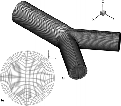
A series of tests was done in order to evaluate the validity of the simulations performed and achieve grid independent results. A numerical simulation that represents the peak inhalation phase with Reynolds number equal to 1250 was used as a grid independence test case. The computations were carried out for three consecutively finer meshes consisting of 466.200, 665.496, and 1.087.506 hexahedral elements, entitled GI, GII, and GIII, respectively.
In order to quantify the difference of the flow fields predicted by the different grids, a calculation of the root mean square ϵrmsof the relative error ϵ of the velocity magnitude at 70 geometrical points inside the flow field is made. The relative error for the velocity magnitude is calculated by EquationEquation (9) while the root mean square of the relative error is calculated by Equation (10)
The velocity magnitude is calculated for the three meshes and the differences in terms of ϵrms between GI and GII and between GII and GIII are summarized in .
TABLE 1 Relative square error comparison for three consecutively finer computational domains
Due to the high quality of the hexahedral computational domain with the butterfly topology that ensures element alignment with the predominant flow and sufficient grid clustering near the wall, all the computational domains present negligible differences. The calculated values of ϵrms are 1.15% between GI and GII and 0.61% between GII and GIII. These results suggest that all the computational domains are of an excellent quality and produce grid independent flow fields. Therefore, GI would be the better choice, combining flow field solution independency at sufficient level with good computational speed and a size of the computational elements near the wall region varying from 50 to 60 μm.
NB–HFOV
As an inlet boundary condition, we imposed a sinusoidal velocity waveform at the entrance of the G3–G4 region for both cases. A frequency equal to 0.25 Hz is imposed as the NB waveform and a waveform with frequency equal to 16 Hz for the HFOV case. The boundary condition for the fluid velocity on the wall is a no-slip condition. The two cases produced the same peak Reynolds number equal to 1250 defined from the maximum inlet velocity at the peak inhalation time phase. The Reynolds number is calculated by EquationEquation (11),
For the NB case a tidal volume equal to 0.10075 l is produced and for the HFOV a tidal volume equal to 0.00157422 l is produced. The NB pattern gives a minute ventilation equal to 1.5 l/min, a result which is rational based on the fact that the trachea minute ventilation is estimated between 5 and 10 l/min and the simulation is done for one of the four G3–G4 bifurcations of the human lung.
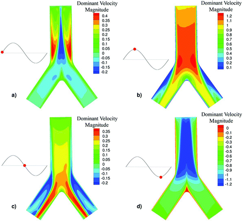
FIG. 2 Contour of the dominant velocity magnitude at the plane symmetry of PBR for the HFOV case for four different time phases (a) inhalation start, (b) inhalation peak, (c) flow reversal, and (d) exhalation peak.
The Womersley number is a dimensionless expression of oscillating flow frequency in relation to viscous forces. Womersley number was defined during an attempt of solving the equations of viscous fluid motion for the fluid flow in a circular tube under a time periodic pressure gradient (Womersley Citation1955). The Womersley number is defined by EquationEquation (13),
TABLE 2 Summary of flow characteristics for HFOV and NB cases
TABLE 3 Spherical particle diameters and Stokes number
Particles
In the developed particle dynamics model, the dispersed phase is simulated as a monodisperse particle population with density considerably higher that the fluid. In order to have an insight of the particle deposition mechanisms and evaluate, the use of HFOV for targeted drug delivery, simulation for 6 different particle sizes has been carried out. The particles are assumed spherical with diameter equal to 1 nm, 50 nm, 100 nm, 900 nm, 5 μm, and 10 μm respectively. Transport and deposition for all particle sizes has been studied for both HFOV and NB conditions. In , the particle diameter, the Stokes number and the corresponding particle relaxation time are presented.
The calculation of particle transport and deposition of inert particles based on small particle relaxation time has been validated against experimental data (Pui et al. Citation1987) for particles of sizes 5.5 to 20 μm (Pilou et al. Citation2011). The conclusion is that small particle time approximation is valid for particles of those sizes. Therefore, the small particle relaxation time approximation is valid for the particle sizes studied in this study (from 1 nm to 10 μm).
FIG. 3 Contour of the dominant velocity magnitude at the plane symmetry of PBR for the NB case for four different time phases (a) inhalation start, (b) inhalation peak, (c) flow reversal, and (d) exhalation peak.
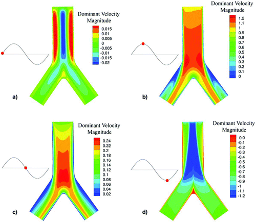
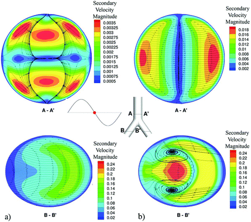
FIG. 4 Surface streamlines and secondary velocity contour magnitudes at a plane near the exit of the G3–G4 bifurcation at the flow reversion phase for (a) HFOV and (b) NB cases.
At the inlet of the bifurcation a constant uniform (plug) concentration particle profile, for the whole time of the numerical simulation, is assumed. Regarding wall boundary conditions, the usual condition of a totally absorbing wall for particle concentration described by EquationEquation (14) is used
Moreover, there is a finite nonzero particle convective velocity just before the wall, resulting to a (dimensionless) convective flux, JC |wall, which can be written as:
Therefore, once a particle hit the wall, it is assumed to deposit on it without being able to re-enter the flow field. It has to be noted that for the calculation of the deposition flux towards the wall, particle velocity is only available at the cell center of the boundary grid cell. As a result the particle velocity at the wall is approximated as the value at the cell center of the nearest control volume. In this case, a possible particle deceleration between the control volume cell center location and the wall surface may cause an over estimation of the deposition flux due to inertia. However, this boundary condition is widely used and considered valid in studies of particle deposition inside rooms, cases where the particle diameter is orders of magnitude smaller than the boundary grid cells (Zhao et al. Citation2008; Parker et al. Citation2010). For this simulation, the distance between the cell center and the wall (25–30 μm) is directly comparable with the diameter of the particles. Thus, we may assume that there is no significant deceleration of the particles and no overestimation of the particle deposition flux due to inertia.
It has to be noted that a “higher order” approach to similar boundary conditions has been introduced by Longest and Oldham (Citation2008), who added a velocity correction calculation between the wall and the nearest cell center in order to asses particle deposition. However, our “lower order” approach for the boundary conditions has been compared with experimental data in previous publications (Pilou et al. Citation2011, Citation2013) and produced good results.
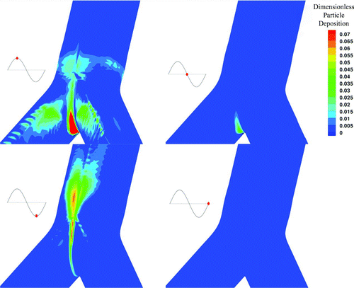
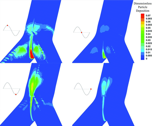
FIG. 5 Contour of particle deposition for 900 nm particles, around the area of the carinal ridge for the HFOV case at different time phases.
RESULTS
Fluid
The HFOV velocity profiles significantly differ from the profiles of the NB case. During HFOV, the core flow is less influenced by the boundary layers and exhibits strong phase lags in the flow reversion. On the other hand, in the NB case the core flow approximately follows the pressure gradients.
In the HFOV case strong counter flow (inspiratory and expiratory fluid streams coexistence) is present near the walls while in the NB case almost no counter flow is present. In , the dominant velocity magnitude is illustrated in a color contour for the HFOV case for four different time phases of the flow (a) inhalation start, (b) inhalation peak, (c) flow reversal, and (d) exhalation peak; while in , the respective time phases for the NB case are illustrated. The strong counter flow in the HFOV case is easily visible at the flow reversal phase while the flow in the NB case is one-way at almost every time step. This remark is consistent with Heraty et al. (Citation2008) and Lunkenheimer et al. (Citation1972) who concluded that the increase of oscillation frequency will increase the counter flow effect. For the HFOV case, higher velocity profiles are observed at the core of the tube and thinner boundary layers near the wall. The formation of the thinner boundary layers is expected based on the fact that the HFOV case has greater Womersley number than the NB case.
Furthermore, the secondary flows on cross sections near the two outlets show additional differences of the HFOV against NB flow fields. Surface streamlines and secondary velocity contour magnitudes for defined planes are presented for both cases in (named A—A′ plane near the end of the main branch and named B–B′ plane near the middle of the left bifurcation leg). For the HFOV case a strong pair of vortices is found in both daughter airways near the exit of the bifurcation. For the NB condition, these vortices cannot be observed. Moreover, the HFOV case presents stronger secondary flows with higher velocity magnitude than the NB case. This remark is critical because secondary flows are reported to be strongly related with particle deposition (Hofmann et al. Citation2001). For both cases, the region near the carinal ridge remains less influenced in every flow inversion and presents small fluid velocities almost at any flow phase. This fact leads to particle “entrapment” and increased deposition near the carinal ridge wall.
It should be noted that a slight asymmetry is present for axial velocity contours between the bifurcation legs due to the rapid change in the pressure gradient. The asymmetry in bifurcating flow has been previously described in literature by experimental (Lieber and Zhao Citation1998) and computational studies (Hofmann et al. Citation2001; Zhang and Kleinstreuer Citation2002).
Particles
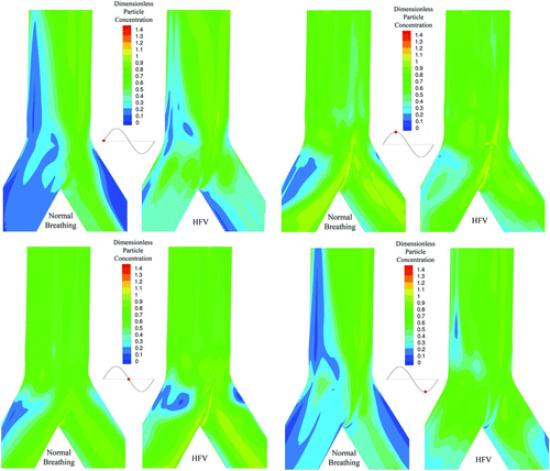
One of the main advantages of the Eulerian approach is that it allows an easy calculation of particle concentration profiles. In , particle deposition for the HFOV case is illustrated for four time phases. In , particle deposition for the NB case is illustrated for four different time phases. For both cases the particle size is equal to 900 nm. The respective time phases are illustrated as red dots on the sinusoidal graph that is at the left of every picture in both Figures. The time phases are representing peak inhalation, flow reversion, peak exhalation, and second flow reversion at the sinusoidal inlet. The deposition has been calculated based on the definition of our boundary condition described by Equations Equation(15)–Equation(18) in the manuscript and the visualization is done on the bifurcation wall. It has to be noted that the carinal ridge is the area with the higher particle deposition during all time phases. Furthermore, by the two figures is visible that HFOV case shows particle deposition in time phases where respectively the NB case does not. The spatial distribution of particle concentration, for particles with diameter equal to 900 nm, under HFOV and under NB near the wall boundary is presented in . The numerical simulation is done on a collocated numerical grid arrangement and the concentration is illustrated on one computational node before the wall due to the totally absorbing wall boundary condition that forces the concentration to be zero at the boundary node. The color scale was chosen to vary from 0.0 to 1.4 in order to visualize the dimensionless particles concentration profiles.
In the HFOV case due to the enhanced secondary flows, a substantial amount of particles deposit on the outer wall of the bifurcation legs. Furthermore, during the HFOV case, higher particle deposition is located near the carinal ridge.
Comparison
In order to produce a measurement comparison of the particle deposition under the two cases, the deposition fraction was calculated for every particle size. The fraction of the deposited particles in the PBR, η, is calculated by EquationEquation (19),
TABLE 4 Deposition fraction of all particle sizes used in the simulation presented for HFOV and NB cases
The amount of aerosol deposition during HFOV and NB is numerically evaluated for six different particle sizes. In , the deposition fraction for both cases and for different particle sizes is summarized. The proposed model predicted the U-shaped dependence of deposition fraction on particle diameter reported by series of particle deposition studies (Hofmann Citation2011).
The HFOV shows stronger deposition for all the particle sizes. In contrast with the conclusion that HFOV would enhance the longitudinal gas transport and push gases into further generation, inertia particles show different behavior.
The mechanisms of enhanced Secondary flows combined with strong counter flow and thinner boundary layers under the HFOV case, augment the particles deposition on the boundary walls. The particle transport and deposition mechanisms enhance deposition under HFOV compared with the NB case. This statement is enhanced by the illustrations presented in and , where it is visible that HFOV shows particle deposition in time phases where respectively the NB case does not.
The results are consisted with other experimental and numerical studies who concluded that particle deposition in a lung model would be higher under HFOV (Alzahrani Citation2010) and that application of HFOV would force particles to deposit on the endotrachial tube of a pressurized meter dose inhaler medical device on an overwhelming percentage (Garner et al. Citation2000).
DISCUSSION AND CONCLUSION
The current study is a computational simulation of transport and deposition of inertial particles, under HFOV and NB conditions, inside a PRB. The computational simulation is based on a fully Eulerian (fluid and particles) model that incorporates particle inertia and diffusion at the same time. The proposed simulation offers a spatial accurate analysis that gave us insight into the particle dynamics under high-frequency oscillating flow fields.
Particle dynamics and deposition analysis for six different particle sizes under two oscillatory cases (HFOV and NB) showed that different mechanisms take part compared to the mechanisms of gas transport. Although the enhancement of the longitudinal gas transport through a forced diffusion mechanism pushes gases into further generation of the bronchial tree, the same flow field functions different when it comes to particle deposition.
The highly oscillating field (HFOV) showed stronger secondary flows, thinner boundary layers and strong counter flow that accumulates and deposit particles further than a lower frequency oscillatory field (NB).
Aerosol drug deposition under HFOV will conclude to stronger deposition on the upper generations of the bronchial tree compared to NB. The effectiveness of that technique may be considered based on the target of the specific aerosol drug, count on the fact that the aerosol drug may not reach the lower generations of the bronchial tree and will mainly deposit on the upper generations.
SUPPLEMENTAL MATERIAL
Supplemental data for this article can be accessed on the publisher's website.
Supplemental.zip
Download Zip (67.9 KB)REFERENCES
- Alzahrani Walled , A. 2010 . Comparison of Albuterol Delivery between High Frequency Oscillatory Ventilation and Conventional Mechanical Ventilation in a Simulated Adult Lung Model using Different Compilance Levels. Respiratory Therapy Theses , Thesis. Georgia State University, Division of Respiratory Therapy Paper 10 .
- Briant , J. K. and Lippmann , M. 1992 . Particle Transport Through a Hollow Canine Airway Cast by High-Frequency Oscillatory Ventilation . Exp Lung Res. , 18 : 385 – 407 .
- Choi , J. , Xia , G. , Tawhai , M. H. , Hoffman , E. A. and Lin , C. L. 2010 . Numerical Study of High-Frequency Oscillatory Air Flow and Convective Mixing in a CT-Based Human Airway Model . Ann. Biomed. Eng. , 38 ( 12 ) : 3550 – 3571 .
- Clark , R. H. , Gerstmann , D. R. , Null , D. M. , Yoder , B. A. , Cornish , J. D. Glasier , C. M. 1986 . Pulmonary Interstitial Emphysema Treated by High-Frequency Oscillatory Ventilation . Crit. Care Med. , 14 ( 11 ) : 926 – 930 .
- Derdak , S. , Mehta , S. , Stewart , T. E. , Smith , T. , Rogers , M. , Buchman , T. G. , Carlin , B. , Lowson , S. and Granton , J. 2002 . High-Frequency Oscillatory Ventilation for Acute Respiratory Distress Syndrome in Adults: A Randomized, Controlled Trial . Am. J. Respir. Crit. Care Med. , 166 ( 6 ) : 801 – 808 .
- Druzhinin , O. A. 1995 . On the Two-Way Interaction in Two-Dimensional Particle-Laden Flows: The Accumulation of Particles and Flow Modification . J. Fluid Mech. , 297 : 49 – 76 .
- Ferry , J. and Balachandar , S. 2001 . A Fast Eulerian Method for Disperse Two Phase Flow . Int. J. Multiphase Flow , 27 : 1199 – 1226 .
- Fredberg , J. J. , Glass , G. M. , Boynton , B. R. and Frantz , I. D. 3rd. 1987 . Factors Influencing Mechanical Performance of Neonatal High-Frequency Ventilators . J. Appl. Physiol. , 62 ( 6 ) : 2485 – 2490 .
- Garner , S. S. , Wiest , D. B and Bradley , W. 2000 . Albuterol Delivery by Metered-Dose Inhaler in a Pediatric High-Frequency Oscillatory Ventilation Model . Crit. Care Med. , 28 ( 6 ) : 2086 – 2089 .
- Heraty , K. B. , Laffey , J. G. and Quinlan , N. J. 2008 . Fluid Dynamics of Gas Exchange in High-Frequency Oscillatory Ventilation: In vitro Investigations in Idealized and Anatomically Realistic Airway Bifurcation Models . Ann. Biomed. Eng. , 36 ( 11 ) : 1856 – 1869 .
- Hirahara , H. , Iwazaki , K. , Ahmmed , M. U. and Nakamura , M. 2011 . Numerical Analysis of Air Flow in Dichotomous Respiratory Channel with Asymmetric Compliance under HFOV Condition . J. of Fl. Sci. Tech. , 6 ( 6 ) : 932 – 948 .
- Hofmann , W. 2011 . Modelling Inhaled Particle Deposition in the Human Lung – A Review . J. Aer. Sci. , 42 : 693 – 724 .
- Hofmann , W. , Balashazy , I. and Heistracher , T. 2001 . The Relationship between Secondary Flows and Particle Deposition Patterns in Airway/Bifurcations . Aer. Sci.Tech. , 35 : 869 – 859 .
- Joshi , C. H. , Kamm , R. D. , Drazen , J. M. and Slutsky , A. S. 1983 . An Experimental Study of Gas Exchange in Laminar Oscillatory Flow . J. Fluid Mech. , 133 : 245 – 254 .
- Krishnan , J. R. and Brower , G. 2010 . High Frequency Oscillation in Acute Lung Injury and ARDS . Ch. , 118 ( 3 ) : 795 – 807 .
- Lieber , B. and Zhao , Y. 1998 . Oscillatory Flow in a Symmetric Bifurcation Airway Model . Ann. Biomed. Eng. , 26 : 821 – 830 .
- Longest , W. and Oldham , M. 2008 . Numerical and Experimental Deposition of Fine Respiratory Aerosols: Development of a Two-Phase Drift Flux Model with Near-Wall Velocity Corrections . J. Aer. Sci. , 39 ( 1 ) : 48 – 70 .
- Lunkenheimer , P. P. , Rafflenbeul , W. , Keller , H. , Frank , I. , Dickhut , H. H. and Fuhrmann , C. 1972 . Application of Transtracheal Pressure Oscillations as a Modification of “Diffusing Respiration” . Br. J. Anaesth. , 44 ( 6 ) : 627
- Makris , E. , Neofytou , P. , Tsangaris , S. and Housiadas , C. 2012 . A Novel Method for the Generation of Multi-Block Computational Structured Grids from Medical Imaging of Arterial Bifurcations . Med. Eng. Phys. , 34 ( 8 ) : 1157 – 66 .
- Maxey , M. R. 1987 . The Gravitational Settling of Aerosol Particles in Homogeneous Turbulence and Random Flow Fields . J. Fluid Mech. , 174 : 441 – 465 .
- Parker , S. , Nally , J. , Foat , T. and Preston , S. 2010 . Refinement and Testing of the Drift- Flux Model for Indoor Aerosol Dispersion and Deposition Modelling . J. Aer. Sci. , 41 : 921 – 934 .
- Pui , D. , Romay-Novas , F. and Liu , B. 1987 . Experimental Study of Particle Deposition in Bends of Circular Cross Section . Aerosol Sci. Technol. , 7 : 300 – 315 .
- Pilou , M. , Antonopoulos , V. , Makris , E. , Neofytou , P. , Tsangaris , S. and Housiadas , C. 2013 . A Fully Eulerian Approach to Particle Inertial Deposition in a Physiologically Realistic Bifurcation . App. Math. Mod. , 37 ( 8 ) : 5591 – 5605 .
- Pilou , M. , Tsangaris , S. , Neofytou , P. , Housiadas , C. and Drossinos , Y. 2011 . Inertial Particle Deposition in a 90B° Laminar Flow Bend: An Eulerian Fluid Particle Approach . Aer. Sci. Tech , 45 : 1376 – 1387 .
- Scholz , A.-W. , Krenkel , L. , Terekhov , M. , Friedrich , J. , Rivoire , J. , Kobrich , R. Wolf , U. 2011 . Magnetic Resonance Imaging and Computational Fluid Dynamics of High Frequency Oscillatory Ventilation (HFOV). In Fundamental Medical and Engineering Investigations on Protective Artificial Respiration . Notes on Numerical Fluid Mechanics and Multidisciplinary Design , 116 : 107 – 128 .
- Siegel , R. and Sparrow , E. M. 1959 . Transient Heat Transfer for Laminar Forced Convection in the Thermal Entrance Region of Flat Ducts . J. Heat Tran. February , : 29 – 36 .
- Sood , B. G. , Shen , Y. , Latif , Z. , Galli , B. , Dawe , E. J. and Haacke , E. M. 2010 . Effective Aerosol Delivery During High-Frequency Ventilation in Neonatal Pigs . Resp. , 15 : 551 – 555 .
- The Acute Respiratory Distress Syndrome Network . 2000 . Ventilation with Lower Tidal Volumes as Compared with Traditional Tidal Volumes for Acute Lung Injury and the Acute Respiratory Distress Syndrome . N. Engl. J. Med. , 342 ( 18 ) : 1301 – 1308 .
- Watson , E. J. 1983 . Diffusion in oscillatory pipe flow . J. Fluid. Mech. , 133 : 233 – 244 .
- Womersley , J. R. 1955 . Method for the Calculation of Velocity, Rate of Flow and Viscous Drag in Arteries When the Pressure Gradient is Known . J. Physiol. , 127 : 553 – 563 .
- Zhang , Z. and Kleinstreuer , C. 2002 . Transient Airflow Structures and Particle Transport in a Sequentially Branching Lung Airway Model . Ph. Fluid. , 14 : 862 – 880 .
- Zhao , B. , Yang , C. , Yang , X. and Liu , S. 2008 . Particle Dispersion and Deposition in Ventilated Rooms: Testing and Evaluation of Different Eulerian and Lagrangian models . Build. Environ. , 43 ( 4 ) : 388 – 397 .

