Abstract
A rectangular slit micro-aerodynamic-lens (μADL) aerosol concentrator operating at atmospheric pressure has been developed. A single stage version has shown concentration ratios of up to 40:1 for 1 μm aerosol particles while particles larger than 2 μm can be concentrated by more than 100:1 in a single stage. The design of this device has been guided by unsteady 3D CFD modeling using detached eddy simulations (DES), and has been validated experimentally using polystyrene spheres and salt crystals of known aerodynamic diameters. The pressure drop in the device does not exceed 1.5 kPa in the major flow and 0.3 kPa in the minor flow at a total flow of 10 slpm.
Copyright 2014 American Association for Aerosol Research
INTRODUCTION
Atmospheric aerosols from a variety of sources including natural, anthropogenic, and industrial processes, and from chemical and biological weapons (CBW) are potential threats to human health. Particle sensors designed to detect and characterize atmospheric aerosols are often flow limited; therefore, in order to provide a sufficient number of particles to the detector in an acceptably short period of time, it is necessary to sample large volumes of air at a high flow rate and concentrate the aerosol to provide a concentrated sample at a flow rate that the detector can handle. Concentrating particles in the range of 1 to 10 μm diameter is of particular interest since this size range corresponds to the size of many bio-aerosols; particles of this size have high inhalation and lung deposition efficiency; see, for example, Hinds (Citation1999). Several approaches are currently used for aerosol particle concentration and collection in the target size range, most of which are based on the inertial properties of the aerosol particles. Devices employing these approaches include cyclones, inertial impactors, settling chambers, virtual impactors, liquid impingers, inertial particle separators, etc. Each of the devices is able to separate aerosol particles from major flow, and some of these technologies are able to deliver an airborne, concentrated particle stream for analysis using a small fraction of the transport air. The design of such devices is often complicated because, despite their relatively simple construction and principle of operation, the governing set of equations describing the airflow and particle motion is fairly complex.
The most commonly used device for sampling and concentrating particles in the respirable size range is the virtual impactor whose principle of operation and design are described in several text books, for example, Vincent (Citation1989), Willeke and Baron (Citation1993), and Hinds (Citation1999), and technical papers, for example, Marple and Chien (Citation1980), Sioutas et al. (Citation1994a), Chen and Yeh (Citation1987), and Lawrence et al. (Citation2004), that show successful concentration of particles from diesel exhaust to coarse particulate matter; these reports provide an extensive theoretical and experimental base of knowledge about these devices. In a virtual impactor, ambient air is aspirated into the device and accelerated in one or more nozzles; the inertia of the accelerated particles allows them to be separated from the bulk (major) flow as the flow is split into minor (particle rich) and major (particle lean) streams. Particles with higher momentum are collected in the minor flow while smaller particles exit with the major flow according to the impactor cutoff characteristics. Sampling of environmental aerosols using virtual impactors has been described in a number of studies, for example, Lundgren et al. (Citation1996) and Marple et al. (Citation1995), and some are particularly concerned with bio-aerosols (Romay et al. Citation2002; Park et al. Citation2009a,Citationb). While these devices are well understood and have been refined to a great extent, their performance is less than optimal.
Coupling a virtual impactor with an aerodynamic lens (ADL) provides an effective method of enhancing overall performance by aerodynamically focusing the particles into a narrow beam surrounded by particle-depleted air prior to separation from the major flow in the virtual impactor section of the concentrator. ADL consist of a series of orifices of decreasing size through which a dilute aerosol is aspirated. For laminar flow conditions, as the gas flows through this series of orifices, the fluid flow forces particles smaller than a specific size and Stokes number into a narrow beam along the centerline, while the majority of the gas flow away from the centerline is left virtually free of particles (Schreiner et al. Citation1998). In its original form (Liu et al. Citation1995a,Citationb), and in the majority of ADLs in use today, the ADL is used alone without a virtual impactor. The aerosol is aspirated from the atmosphere through a pressure-limiting orifice which reduces the operating pressure in the flow to few hundred Pascals. The ADL is merely used to focus the aerosol into a collimated particle beam which is delivered to downstream components at very low pressure. This is particularly beneficial for detection systems operating at low pressure such as mass spectrometers (Ziemann et al. Citation1995; Schreiner et al. Citation2002; Shu et al. Citation2010) and other single particle analyzers (Benner et al. Citation2008; Park 2009b). It has also been shown that ADLs can be operated successfully at higher pressures (Schreiner et al. Citation1999), as well as at atmospheric pressure (Lee et al. Citation2003; Deng et al. Citation2008).
Because of the complexity of the flow and the coupling between fluid and particle motion, optimization of the design of the ADL must be guided by CFD simulations (Zhang et al. Citation2002, Citation2004; Wang et al. Citation2005a,Citationb; Liu et al. Citation2007). However, CFD modeling of the complex fluid system is often time consuming and requires an iterative approach. One common approach for minimizing the computational demand of the simulation is to use the details of the fluid flow—derived from the numerical simulation—to determine particle trajectories resulting from the drag forces experienced by the particles seeded into the flow, while the particles are assumed to have no reciprocal effect on the fluid. Wang and McMurry (Citation2006) describe such an approach for designing low pressure ADL systems using CFD simulations of flow and particle transport in the ADL based on its geometry and operating conditions.
While many ADLs in use today are based on a cylindrical geometry, several researchers have studied rectangular slit concentrators for both ADLs and virtual impactors (Ravenhall et al. Citation1978; Forney et al. Citation1982; Sioutas et al. Citation1994a,Citationb; Fernandez de la Mora Citation1996; Ding and Koutrakis Citation2000; Middhal and Wexler Citation2006; Hu and McFarland Citation2008). A slit virtual impactor has a significant advantage over a single nozzle impactor due to the increased flow area for a given critical dimension (slit width) which allows for an increased sampling flow rate. In the case of the slit ADL, an additional major benefit of the rectangular slit geometry is the ability to avoid the onset of the turbulence by avoiding increased Reynolds number at higher flow rates. Since the velocity is inversely proportional to the width of the channel, the Reynolds number remains constant throughout the lens. This allows the rectangular ADL to operate in the laminar regime even though the flow is accelerated to high velocity as the channel width decreases. In contrast, in a cylindrical ADL, at a given volumetric flow rate, the Reynolds number varies inversely with the channel diameter. This often results in high Reynolds numbers and a transition to turbulence as the channel diameter decreases. This can significantly reduce the efficiency of the concentrator due to loss of particles to the internal walls via turbulent dispersion and can result in fouling of the internal surfaces. In addition, at high flow rates in a cylindrical ADL, there may be a transition to compressible flow in the final focusing orifice due to its small cross sectional area which requires the flow to be accelerated to near-sonic velocity in order to accommodate the desired flow rate. This will result in a large pressure drop which limits the utility of the device due to the large power requirement.
In this article, we discuss the design and performance of a rectangular slit ADL aerosol concentrator operating at atmospheric pressure, an inlet flow rate of 10 slpm, and a target particle size range of 0.8–15 μm. We describe the analytical relations used to design the major geometrical features of the ADL; we describe the numerical approach and CFD simulations used in optimizing the geometry of the concentrator; we describe the experimental methods used to test the device; and we compare the experimental results to the modeling predictions of the performance of the ADL concentrator.
Design Based on Analytical Calculations
While CFD modeling can provide detailed simulations of complex flow structures for a given geometry, and can be used to refine the geometry through an iterative process of modeling the flow and adjusting the geometry, it is often desirable to utilize one-dimensional analytical modeling as a first step to identify a suitable geometry to use as a starting point. In the case of the ADL, several constraints must be satisfied to ensure effective focusing of particles within the ADL. Goo (Citation2002) has shown that in a geometry where a rectangular inlet channel of width “W” is followed by an orifice of width W/3 and an outlet channel of width W/2, there is an optimum Stokes number that will result in perfect focusing of the aerosol particles of a given diameter, and that this optimum Stokes number depends on the Reynolds number of the flow.
The Stokes number is defined as
Optimization of the Design Guided by CFD Simulation
Although the analytical calculations allow one to accurately predict the optimal slit dimensions and the fluid volume downstream of the slit they do not provide information about the three-dimensional flow field inside the ADL. The ADL structure contains forward and backward facing steps and may produce complex flow patterns especially in the virtual impactor region where the major and minor flows are separated. Particle behavior is highly coupled to fluid motion inside the ADL making it essential that the design suppresses turbulence, the development of recirculation zones, and unsteady fluid motion which may occur in localized regions of the flow even when the average properties at a given cross section don't predict these effects. The choice of a numerical modeling technique for this application is guided by its ability to capture transient laminar flow behavior and the transition to turbulence, as well as its ability to handle particle-flow interactions.
Two major particle loss mechanisms were explored using CFD modeling of the ADL: inertial impaction and gravitational settling. Other mechanisms, such as electrostatic forces, Brownian diffusion, thermophoretic, and Safman forces can be important in certain scenarios; these were evaluated but not included in this analysis since these mechanisms are relatively insignificant for the particle sizes and flow velocities studied, and since the use of conductive materials in the ADL structure minimizes electrostatic attraction of particles to the walls. Although gravitational settling is often neglected for particles in the target particle size range due to their low settling velocities, gravitational settling can be a significant source of particle loss. We have found that if the flow direction is perpendicular to gravity, particles that enter the device close to the lower edge of the inlet can settle on the wall due to their proximity to the boundary layer. Entrainment of particles into flow recirculation zones can significantly increase particle residence times, making them comparable to the particle settling times; this can result in particle loss to the wall.
Numerical Approach
Steady state laminar and Reynolds averaged Navier-Stokes (RANS)-based turbulence modeling approaches have been used in many CFD applications due to their ability to handle many laminar flow situations. However, both laminar and RANS-based models are ill-equipped to handle transient fluid flow behavior which characterizes phenomena such as laminar to turbulent transition or bluff-body aerodynamics. Many of these situations involve large-scale coherent flow structures such as recirculation zones and eddies that significantly reduce the accuracy of the flow predictions when a steady-state approach is used. In the optimization of the ADL concentrator, time dependent CFD simulations have been used to develop the final design. These simulations address potential flow instabilities inside the geometry at forward and backward facing steps, in the minor/major flow separation region, and at 3D corners. In order to capture the details of the transient flow, a detached eddy simulation (DES) approach was chosen due to its ability to predict possible transition to turbulent flow, instantaneous flow characteristics and resolve flow structures. A standard wall function approximation with realizable k-ϵ model was used in the near wall regions of geometry. To avoid numerical viscosity in the CFD simulations, a second order convergence scheme was used. Simulations were performed using a commercial software package (Fluent™ 12.1).
Two different methods were considered for modeling particle transport in the flow: Eulerian and Lagrangian. In the Eulerean, or mixture fractions approach, the particles are regarded as a continuous phase for which the conservation equations (continuity, momentum, and energy) are solved in a fashion similar to that of the carrier gas flow field. In the Lagrangian approach, the particles are treated as a discrete phase dispersed in the continuous fluid flow. While the former approach is useful when a strong two-way coupling between fluid and particles exists, it does not handle particle-wall interactions well. The Lagrangian particle tracking technique was chosen for these simulations due to its ability to handle the relevant forces acting on the particles and accurately model particle behavior near the wall. Due to the dilute nature of atmospheric aerosols the particles do not appreciably affect the fluid flow so two-way coupling is not necessary. In both the 2D and 3D simulations, particles were assumed to stick to the walls upon impact.
An initial 2D simulation using a laminar, steady-state solver and a 2D structured grid with 100,000 to 200,000 cells was performed for a three slit ADL geometry chosen based on analytic calculations. Details of the simulation parameters are shown in . The Reynolds number is calculated based on the wetted diameter of the rectangular, 25 mm high channel; the slit widths were chosen to focus the targeted particle sizes. The slight increase in the Reynolds number from slit 1 to slit 3 reflects the slight differences in the slit aspect ratios. While slit width was used for Reynolds number calculation in the 2D simulations, in 3D analysis wetted diameter is a more appropriate parameter for Reynolds number calculations.
TABLE 1 Design parameters for 2D ADL simulation
For 3D simulations a structured grid was constructed employing about two million cells for a quarter of the geometry taking advantage of planar symmetries of the ADL. The grids in the boundary layer and in regions of maximum pressure–velocity gradient were adapted to achieve solution convergence at each time step (at least 5 orders magnitude reduction for residuals).
, top, shows the flow field calculated using 2D CFD simulation and the inset in (lower left) shows flow streamlines and 0.8 μm particle trajectories. The 2D mesh consists of 100,000 rectangular elements with maximum aspect ratio of 1.5. The major/minor flow split of 20:1 is set by assigning the flow fractions as outflow boundary conditions for the major and minor outlets. The velocity at the inlet is specified corresponding to the chosen Reynolds number. The flow is then calculated using a coupled laminar solver with a second order convergence scheme to avoid the effects of numerical viscosity. (lower left) shows the separation of 0.8 μm particles (smooth lines) from the flow streamlines (grey lines with arrows) in the last concentration slit (raceway): the majority of the streamlines exit through the major flow channel while the particles are forced to the center-plane by the third focusing slit and then projected into the minor flow channel.
FIG. 1 Top: velocity magnitude (m/s) contours for 2D numerical simulation of the aerodynamic lens. Inset, lower left: flow streamlines (gray lines with arrows), and 0.8 μm particle trajectories (black lines).
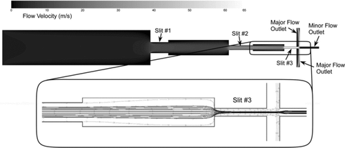
The laminar 2D simulations confirm the analytical predictions of particle focusing by the individual slits shown in ; 5 μm particles are focused by slit one, 2 μm particles–by slit two, and 0.8 μm particles–by slit three. Although these 2D simulations predict near-perfect performance of the ADL, analysis of the CFD simulations reveals several areas where deviations from ideal flow behavior can have a significant adverse effect on particle trajectories. The 2D modeling suggests that poorly designed internal geometry in the ADL can lead to formation of undesirable flow patterns, such as recirculation areas, transition to turbulence, unsteady flow leading to poor particle focusing, transmission losses (losses due to deposition of particles on the inner walls of the ADL by inertial impaction and gravitational settling), and separation losses (entrainment of particles into the major flow in the separation region due to poor particle focusing and cross-stream mixing).
Slit Region Design
In order to avoid particle losses in the concentrator, the flow field has to be optimized to minimize flow instabilities and particle deposition inside the device. The converging/diverging geometry of each focusing slit should be optimized to suppress the formation of recirculation zones. The strongest recirculation cells develop behind each backward facing step (abrupt channel expansion) and are present over all practical Reynolds number values. These backward facing steps create low-pressure regions which pull the gas streamlines into the region downstream of the step. These recirculation cells create two major problems for particle focusing: particles entrained into the cell will not follow the optimal focusing trajectory; and, due to their naturally unsteady behavior, the cells on opposite sides of the flow in the diverging section will become unstable and cause flow oscillation resulting in excessive mixing, particle beam “wandering” and particle loss to the walls by impaction. Sudden flow expansion represents a classical fluid mechanics problem in the design of flow diffusers, bluff body combustors, etc. (Bluston and Paulson Citation1972; Beer and Chigier Citation1972; Tsui and Wang Citation2007).
Recirculation cells also form in the corners of the forward-facing steps (abrupt contractions) where the flow stagnates. Particles entrained into these cells may impact on the leading edge of the contraction or may settle onto the wall due to their extended residence time in the cell. Finally, a third pair of recirculation cells form just downstream of the abrupt contraction (at the entrance of the slit). Flow separation will occur in each of these regions potentially contributing to particle loss to the walls and increasing the flow resistance (pressure drop and power required to operate the device). By contouring the inner surfaces of the ADL to match the flow streamlines predicted by the 2D CFD modeling, these recirculation cells can all be eliminated. Several studies show that in symmetric expansion, laminar flows develop unsteady asymmetric behavior. It is likely that the cause of asymmetry lies in the instability of the shear layers formed by flow separation. The instability originates from small perturbations in the shear layers, or in adverse pressure gradient regions. These instabilities result in deflection of the jet from the center plane and form wavy flow patterns. As shown in Cherdron et al. (Citation1978), Fearn et al. (Citation1990), and Mizushima et al. (Citation1996), the onset of this type of instability depends on the expansion ratio of the slit/downstream channel and the Reynolds number. From the standpoint of ADL design, we have found that the laminar flow (Re = 600–1000) in the diverging section remains axisymmetric (no beam deflection) and stays attached to the wall at half angles of up to 10 degrees, which compares well with the literature for two-dimensional laminar diffusers and sudden expansions, for example, Chen et al. (Citation1979), Tsui and Wang (Citation1995), and Nabavi (Citation2010). A smaller expansion angle in the diffuser section results in a longer design which may not be practical due to gravitational settling of larger particles during the increased residence time, and also results in an increase in the form factor of the concentrator. Therefore, the recirculation cell downstream of the slit can be eliminated by introducing a gradual, rather than an abrupt, expansion.
Flow over a forward facing step can create two distinct recirculation zones that may lead to the development of flow instabilities and deviation of particles from their optimal focusing trajectories. One such zone is developed upstream of the step when flow turns toward the symmetry plane setting up a zero velocity area in the corner. This cell does not directly impact the focusing of the particles; however, the flow instabilities produced by this cell may cause flow perturbations downstream. The negative effect of these perturbations on the flow and particle trajectories is reported in the literature, for example, Pollard et al. (Citation1996) and Stüer et al. (Citation1999). Minimization of this effect is achieved by contouring the corner in front of the step: a fillet is used to prevent the formation of the cell. The other recirculation zone whose size is related to the flow Reynolds number, is formed at the lip of the sharp forward facing step (the leading edge of the slit) and negatively affects particle focusing. Fortunately, this can be countered by introducing a small radius in the lip geometry, which is also convenient from a device fabrication standpoint.
Design of the Major/Minor Flow Separation Region
One of the most critical areas of the geometry is the region where the separation of the major and minor flows occurs. Due to the adverse pressure gradients behind the backward-facing step that forms the entrance to the major flow channel, and differences in the pressures in the major and minor flow channels, recirculation flow patterns are likely to occur. The presence of these recirculation zones hinders particle separation due to the unsteady nature of the flow and produces de-focusing and cross-stream mixing of the particle stream.
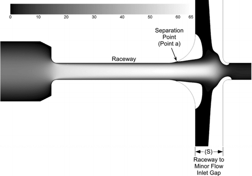
In the design of the major flow inlet in the planar ADL geometry, an analogy with flow over a cylinder (Roshko Citation1954; Schlicting Citation1968) is specifically useful for estimating the boundary layer detachment point. Using 2D and 3D simulations, we have evaluated several major flow inlet geometries. The location of flow separation (point a) in the major flow inlet, and the length of the gap between the raceway and the minor flow inlet (S), shown in , have been observed to have a significant impact on particle beam collimation within the gap. shows x-velocity contours for a 2D laminar simulation where the major flow channel curvature radius is twice the width of the last focusing slit in order to balance the location of the separation point and minimize the length of free jet region. Two major observations can be made in regards to optimizing the major flow inlet channel shape:
| 1. | Particle focusing improves if the flow separation point is moved farther from the symmetry plane. This preserves uniform flow along the centerline in the gap between the final focusing slit and the minor flow inlet. The focused particle beam is shielded from the recirculation cell formed at the boundary layer detachment point and mixing of the particle-rich core with the particle-free outer layers is minimized. In the case of a sharp-edged 90 degree corner at the major flow inlet, the separation point was located right at the lip of the inlet producing a strong shear layer between the flow from the focusing slit and the recirculation cell. In the case of a rounded inlet, the boundary layer detachment point will occur at the 15 degree angle location, as seen in experiments with laminar flow over a cylinder. Thus, in order to move the onset of the recirculation zone away from the particle stream, a rounded (cylinder like) transition from the raceway to the major flow inlet channel is desired. A large radius will move the separation point further from the particle beam than a small radius. | ||||
| 2. | However, a large radius increases the distance (S) between the raceway and the minor flow inlet. We have found that particle concentration (lens performance) improves with decreasing gap length due to decreased size and intensity of the recirculation zone at the major flow inlet. Additionally, a large gap creates a flow similar to a free planar jet impinging on a flat surface (in this case, a virtual stagnation plane inside the minor flow channel where part of the flow rapidly decelerates). If a free jet is allowed to develop, one can expect a transition to turbulent flow and development of unsteady flow structures, both of which will compromise the performance of the concentrator. | ||||
Design of the Focusing Inlet
Inertial impaction of particles on a forward facing step can also be influenced by flow field features such as boundary layer and recirculation zones. The effect of these flow features on particle trajectories is not considered in most analytical models due to the complexity of the flow field. The fate of the particle is a function of its initial position at the inlet plane and potential particle entrainment into recirculation areas. If a particle enters the ADL near the boundary layer and is pulled into a recirculation zone due to gravity, it may not be focused. For example, Goo (Citation2002) showed that for geometry with a right angle forward-facing step, particles introduced at 50% of the height of the inlet channel do not impact on the walls of the structure. However, particles can enter the concentrator inlet over the entire height (and width) of the inlet channel and larger particles that enter close to the wall can impact on the first forward-facing step.
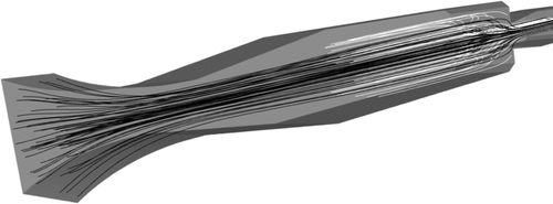
In order to move the larger particles away from the wall before they encounter the first focusing slit, a pre-focusing structure (focusing inlet) was designed. This focusing inlet consists of a smooth, converging-diverging shape that forces larger particles closer to the center of the flow, preventing loss of particles on the side walls due to settling and impaction on the forward facing step. It was found that both converging and diverging sections of the inlet play an important role in determining the particle trajectories. The converging section is necessary to separate larger particles from the stream lines (focusing), while the shape (angle and the length) of the diverging section is important to avoid boundary layer separation due to an adverse pressure gradient at the wall. It was found that, in agreement with the literature (Wilcox Citation1993), divergence half angles less than 10 degrees prevent flow separation. The minimum dimension of the focusing inlet was set to half the width of the inlet channel. The shape of the converging section and the transition between the converging and diverging sections were chosen by iterative, transient, 3D CFD simulations. As shown in , the shape selected for the focusing inlet is an ellipse with major to minor axis ratio of 3:1. This geometry, which minimizes the length of the inlet, was optimized to focus 20 μm particles (twice the targeted size of particles focused in the first slit). Although particles smaller than 20 μm did not focus perfectly, they were displaced from the wall toward the symmetry plane. The 10 μm particles moved to a position half way between the symmetry plane and the wall as seen in which shows 10 μm particle tracks from the 3D simulation. The black particle tracks are for particles introduced at the inlet plane of the ADL and are displaced away from the walls after passing though the constriction, the white particle tracks, also representing 10 μm particles, originated on a cross-section downstream of the prefocusing section which resulted in impaction of almost 50% of the particles on the forward facing step of the first slit. This demonstrates the improvement in performance obtained with the use of the focusing inlet as compared to a concentrator without the inlet.
MODELING RESULTS
The performance of the ADL concentrator has been evaluated using 3D CFD simulations. A series of unsteady DES flow simulations were performed for a variety of conditions including a study of the effect of the prefocusing inlet, and a study of the effects of varying flow splits and flow rates on the ADL performance. In order to determine the concentration efficiencies of the ADL, the inlet plane of the domain was seeded with particles whose initial conditions were matched to the inlet velocity and direction of the air flow at each particle location. The wall-particle interaction type was set for trapping on contact leading to the most conservative efficiency values. For each particle size, the efficiency was calculated as a ratio of the number of particles transmitted to the minor flow outlet divided by the number of particles injected. In the following figures, curves labeled DES indicated that they are derived from transient, 3D, DES.
Effect of Prefocusing Inlet
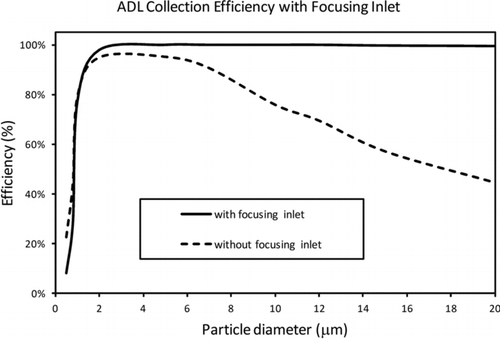
The performance of the prefocusing inlet described above and shown in was modeled using 3D, transient, DES to determine the overall concentration efficiency improvement provided. These results are shown in . The prefocusing inlet is seen to provide significant improvement in the performance of the concentrator for particles larger than 2 μm and is particularly helpful in preventing the loss of large particles by inertial impaction on the first forward-facing step.
Effect of the Flow Split
Flow split is defined here as the ratio of the major flow to the minor flow. For high flow splits, this is nearly the same as the ratio of the total sampled flow to the minor flow. At low flow splits (10:1), the flow in the minor flow channel has sufficient velocity to ensure that particles which enter that channel are carried to the minor flow outlet. However, as the flow split is increased by reducing the minor flow rate, the pressure in the minor flow passage rises creating an adverse pressure gradient which tends to cause the flow to stagnate and be sucked into the major flow passage. This can result in loss of concentration efficiency, especially for the small particle fraction.
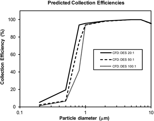
The effect of major/minor flow split on concentration efficiency was studied using transient 3D CFD modeling. In all cases, the sampling flow rate was adjusted to maintain the Reynolds numbers between 800 and 1000. These results are plotted in . The DES CFD modeling suggests that increasing the major/minor flow split causes the efficiency curves to shift toward larger cutoff points. At a 20:1 flow split, the predicted cutoff (50% efficiency) point occurs at a size of about 0.6 μm, but at a flow split of 100:1, the cutoff is shifted to about 0.82 μm.
EXPERIMENTAL RESULTS
In these studies, an ADL concentrator with an inlet measuring 6 × 25 mm, and an overall length of 112 mm was operated at ambient pressure inside a sealed aerosol chamber. The concentrator geometry includes a built-in adapter that connects the slit–shaped minor flow channel to a 1/8 inch round tube. This adapter has been designed to maintain near constant flow velocity and minimize transmission losses. The 1/8 inch diameter minor flow tube can be directly connected to an inline filter holder or to a custom dilution system that introduces additional clean sheath air to match the APS particle counter flow rate. The performance of the ADL concentrator was experimentally tested for several flow conditions and a range of particle sizes. The overall flow rate was held constant at 10 slpm, while the ADL major/minor flow split was varied from 20:1 to 100:1 by varying the flow induced through the major and minor flow passages. Particles of sizes in the range of 0.8 to 5 μm were nebulized from a liquid suspension and introduced into a custom 1 m3 stainless steel aerosol chamber. The large volume of the chamber allowed for sampling with multiple instruments simultaneously, thus removing any ambiguity that might result from temporal variations in aerosol characteristics during a test. Real time particle concentration information was monitored with an aerodynamic aerosol particle sizer (TSI APS 3321). The chamber was maintained slightly below atmospheric pressure and an array of fans was used to keep the aerosol particles in suspension and maintain uniform conditions throughout the chamber. The ADL and reference filters were located inside the chamber. The mass flow rates of the reference filters and ADL concentrator were controlled using mass flow controllers (Sierra Instruments Inc., Monterey, CA, USA).
FIG. 6 Experimental and modeled collection efficiency of the ADL concentrator for Reynolds numbers of 800–900. Major/minor flow splits are: (top) 20:1; (middle) 50:1; (bottom) 100:1.
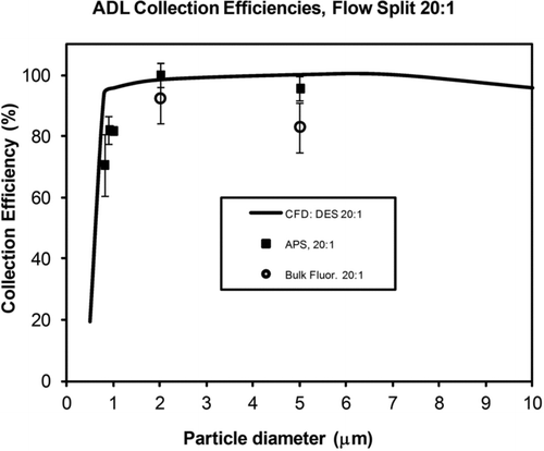
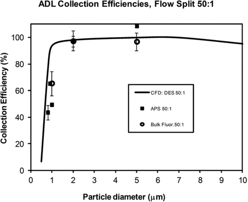
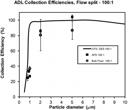
The efficiency of the ADL concentrator was calculated by two independent methods: (i) comparing the amount of aerosol collected on the reference filters and on inline filters placed in the minor flow path of the ADL concentrator, and (ii) real time measurement of the particle concentration in the minor flow the ADL relative to particle concentration measurements in the chamber. In the case of filter collection, two analysis methods were employed: microscopic counting of fluorescent particles collected on membrane filters and bulk florescence of the particles collected on the filters. Of these, the bulk fluorescence method—as in Kesavan et al. (Citation2003)—was found to be the most efficient and reproducible. The experimental measurements were made using mono-disperse fluorescent polystyrene spheres (BangsLabs). Collected particles were eluted from the filters into a 10 ml volume of 0.1% Tween 20 solution. The eluents from the reference filters and the inline ADL minor flow filter were analyzed in one of two spectrofluorometers (Sequoia-Turner 450 or Nanodrop). In the case of in situ particle counting, the APS Model 2231 was used. A dilution apparatus was fabricated and calibrated to address the flow rate mismatch between the APS and the ADL minor flow.
shows a comparison of the CFD modeling predictions and experimental data from the aerosol chamber experiments. The averaged data from the fluorescence measurements are shown by open symbols, the data from the APS measurements are shown by solid symbols. Each plot corresponds to different major/minor flow split determined by the flowrate in the major and minor flow channels of the ADL. The standard deviation for each data point is calculated based on the experimental results at each flow condition. Overall, the data shows good agreement between the experiments and the transient CFD simulations. Both filter-based and in situ particle counting methods have shown consistent results and similar standard deviations. The CFD simulations slightly overpredict the experimentally measured concentration efficiencies for particles below 2 μm and for the 100:1 flow split cases. This is likely due to the development of unsteady flow structures at the entrance to the collector channel at very low minor flow rates.
TABLE 2 50% cut-off particle size for ADL concentrator
These flow structures are likely to develop at low velocities, trapping the smaller particles and causing them to be deposited on internal surfaces of the ADL concentrator by interception or turbulent diffusion. Some deposition of particles smaller than 2 μm was observed following long experimental runs at flow splits of 100:1. Flow splits of 20:1 and 50:1 did not produce significant particle deposition inside the ADL suggesting the existence of well-behaved flow in the major/minor flow separation region.
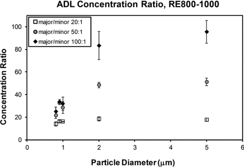
The concentration (enrichment) ratio of the ADL concentrator is equal to the ADL efficiency multiplied by the flow split; it represents the ratio of the aerosol number density in the concentrated (minor flow) stream and that in the aerosol chamber. shows the measured concentration ratio for various major/minor flow splits. The data for each condition represent averages of the filter-based and APS measurements. The theoretical maximum concentration ratios (at 100% efficiency) should be equal to the flow splits themselves. For particles larger than 2 μm, the concentration ratios approach the theoretical maximum values. However, loss of the smaller particles at higher flow split conditions, due to wall deposition and entrainment into the major flow stream, reduces the concentration ratios. compares the CFD predictions and the experimental data for particle size cutoff as a function of flow split.
CONCLUSIONS
An iterative design procedure was used to develop a rectangular slit ADL aerosol concentrator. Analytical calculations based on the particle Stokes number were performed as a first design step, these calculations did not account for possible losses due to particle coupling to the complex flow patterns near the focusing steps and in the major/minor flow separation region. In order to eliminate the onset of flow separations and unsteady flow behavior, the ADL geometry was optimized using 2D and 3D transient CFD modeling. This optimization procedure enabled the development of a design that eliminated recirculation structures that form around the forward and backward facing steps—required for focusing the aerosol stream. The particle losses due to impaction on forward facing step was minimized by the use of a focusing inlet which increased the efficiency of 10 μm particles by 25% and 20 μm particles by 55%.
The modeling and experimental results for collection efficiency show good agreement for particle sizes above 2 μm at all flow splits up to 100:1. The efficiencies for particles larger than 2 μm are consistently greater than 80% independent of the flow split. The behavior of particles smaller than 2 μm depends significantly on the flow split—possibly due to their interaction with complex (transient) flow structures in the virtual impactor section of the ADL concentrator. The CFD simulation and the experimental particle deposition patterns suggest that, at higher flow splits (100:1), time dependent 3D flow structures form in the flow separation region. The somewhat larger discrepancy between the modeled and experimental data for the smaller particles is likely due to limitations in the modeling of the unsteady flow behavior, planar symmetry and boundary condition assumptions used in the modeling, which may not be rigorously valid, and minor errors in manufacturing tolerances relative to the slit width and geometry alignment.
The ADL aerosol concentrator described here provides high concentration ratios for particles with sizes in the range of 1 to 20 μm, and very low pressure drop due to the near-ideal laminar flow characteristics achieved through the use of transient 3D CFD modeling to guide the design.
NOMENCLATURE
| Dp | = |
particle diameter |
| ρ air | = |
air density |
| ρp | = |
particle density |
| ν air | = |
air kinematic viscosity |
| U 0 | = |
air velocity |
| Re | = |
Reynolds number |
| St | = |
Stokes number |
| W slit | = |
slit width |
REFERENCES
- Beer , J. M. and Chigier , N. A. 1972 . Combustion Aerodynamics , London : Applied Science Publisher .
- Benner , W. H. , Bogan , M. J. , Rohner , U. , Boutet , S. , Woods , B. and Frank , M. 2008 . Non-Destructive Characterization and Alignment of Aerodynamically Focused Particle Beams Using Single Particle Charge Detection . J. Aerosol Sci. , 39 ( 11) : 917 – 928 .
- Bluston , H. S. and Paulson , R. W. 1972 . A Theoretical Solution for Laminar Flow Past a Bluff Body with a Separated wake De Mécanique . J. , 11 ( 1) : 161 – 179 .
- Chen , B. T. and Yeh , H. C. 1987 . An Improved Virtual Impactor . J. Aerosol Sci. , 18 : 203 – 214 .
- Chen , R. Y. , Eldighidy , S. M. and Comparin , R. A. 1979 . Laminar Flow of Suspensions in the Entrance Region of a Diffuser . J. Fluids Eng. , 101 : 309 – 312 .
- Cherdron , W. , Durst , F. and Whitelaw , J. H. 1978 . Asymmetric flows and Instabilities in Symmetric Ducts with Sudden Expansions . J. Fluid Mech. , 84 : 13 – 31 .
- Fernandez de la Mora , J. 1996 . Drastic Improvement of the Resolution of Aerosol Size Spectrometers via Aerodynamic Focusing: The Case of Variable-Pressure Impactors . Chem. Eng. Commun , 151 : 101 – 124 .
- Deng , R. , Zhang , X. , Smith , K. A. , Wormhoudt , J. , Lewis , D. K. and Freedman , A. 2008 . Focusing Particles with Diameters of 1 to 10 Microns into Beams at Atmospheric Pressure . Aerosol Sci. Technol. , 42 ( 11) : 899 – 915 .
- Ding , Y. and Koutrakis , P. 2000 . Development of a Dichotomous Slit Nozzle Virtual Impactor . J. Aerosol Sci. , 31 ( 12) : 1421 – 1431 .
- Fearn , R. M. , Mullin , T. and Cliffe , K. A. 1990 . Nonlinear flow Phenomena in a Symmetric Sudden Expansion . J. Fluid Mech. , 211 : 595 – 608 .
- Forney , L. J. , Ravenhall , D. G. and Lee , S. S. 1982 . Experimental and Theoretical Study of a Two-Dimensional Virtual Impactor . Environ. Sci. Technol. , 16 : 492 – 497 .
- Goo , J. 2002 . Numerical Simulation of Aerosol Concentration at Atmospheric Pressure by a Cascade of Aerodynamic Slit Lenses . J. Aerosol Sci. , 33 : 1493 – 1507 .
- Hinds , W. C. 1999 . Aerosol Technology: Properties, Behavior, and Measurement of Airborne Particles. , 2nd ed. , New York : John Wiley & Sons .
- Hu , S. and McFarland . 2008 . Circumferential-Slot Virtual Impactors with Stable Flow . Aerosol Sci. Technol. , 42 ( 9) : 748 – 758 .
- Kesavan , J. S. , Doherty , R. W. and Bottiger , J. R. 2003 . Performance Characterization Methods of Aerosol Samplers , 21010 – 5424 . MD : Report ADA483533, Edgewood Chemical Biological Center .
- Lawrence , J. , Koutrakis , P. , Wolfson , M. , Ferguson , S. and Godleski , J. 2004 . Performance Stability of the Harvard Ambient Particle Concentrator . Aerosol Sci. Technol. , 38 : 219 – 227 .
- Lee , J. , Yi , M. and Lee , S. 2003 . Inertial Focusing of Particles with an Aerodynamic Lens in the Atmospheric Pressure Range . Aerosol Sci. Technol. , 34 : 211 – 224 .
- Liu , P. , Ziemann , P. J. , Kittelson , D. B. and McMurry , P. H. 1995a . Generating Particle Beams of Controlled Dimensions and Divergence: I. Theory of Particle Motion in Aerodynamic Lenses and Nozzle Expansions . Aerosol Sci. Technol. , 22 ( 3) : 293 – 313 .
- Liu , P. , Ziemann , P. J. , Kittelson , D. B. and McMurry , P. H. 1995b . Generating Particle Beams of Controlled Dimensions and Divergence: II. Experimental Evaluation of Particle Motion in Aerodynamic Lenses and Nozzle Expansions . Aerosol Sci. Technol. , 22 ( 3) : 314 – 324 .
- Liu , P. S. K. , Deng , R. , Smith , K. A. , Williams , L. R. , Jayne , J. T. Canagaratna , M. R. 2007 . Transmission Efficiency of an Aerodynamic Focusing Lens System: Comparison of Model Calculations and Laboratory Measurements for the Aerodyne Aerosol Mass Spectrometer . Aerosol Sci, Technol. , 41 ( 8) : 721 – 733 .
- Lundgren , D. A. , Hlaing , D. N. , Rich , T. A. and Marple , V. A. 1996 . PM10, PM2.5, PM1 Data from a Trichotomous Sampler . Aerosol Sci. Technol. , 25 : 353 – 357 .
- Marple , V. A. and Chien , C. M. 1980 . Virtual Impactors: A Theoretical Study . Environ. Sci. Technol. , 14 : 976 – 985 .
- Marple , V. A. , Rubow , K. L. and Olson , B. A. 1995 . Diesel Exhaust and Mine Dust Virtual Impactor . Aerosol Sci. Technol. , 22 : 140 – 150 .
- Middhal , P. and Wexler , A. S. 2006 . Design of a Slot Nanoparticle Virtual Impactor . Aerosol Sci. Technol. , 40 : 737 – 743 .
- Mizushima , J. , Okamoto , H. and Yamaguchi , H. 1996 . Stability of flow in a Channel with a Suddenly Expanded Part . Phys. Fluids. , 8 : 2933 – 2942 .
- Nabavi , M. 2010 . Three-Dimensional Asymmetric flow Through a Planar Diffuser: Effects of Divergence Angle, Reynolds Number and Aspect Ratio . Int. Commun. Heat Mass Transfer , 37 ( 1) : 17 – 20 .
- Park , D. , Kim , Y. , Park , C. W. , Hwang , J. and Kim , Y. 2009a . New Bio-Aerosol Collector Using a Micromachined Virtual Impactor . J. Aerosol Sci. , 40 : 415 – 422 .
- Park , K. , Cho , G. and Kwak , J. 2009b . Development of an Aerosol Focusing-Laser Induced Breakdown Spectroscopy (Aerosol Focusing-LIBS) for Determination of Fine and Ultrafine Metal Aerosols . Aerosol Sci. Technol. , 43 ( 5) : 375 – 386 .
- Pollard , A. , WaKarani , N. and Shaw , J. 1996 . “ Genesis and Morphology of Erosional Shapes Associated with Turbulent flow over a Forward-Facing Step ” . In Coherent Flow Structures in Open Channels , Edited by: Ashworth , P. J. 249 – 265 . Chichester : Wiley .
- Ravenhall , D. G. , Forney , L. J. and Jazayeri , M. 1978 . Aerosol Sizing with a Slotted Virtual Impactor . J. Colloid Interface Sci. , 1 : 108 – 117 .
- Romay , F. J. , Roberts , D. L. , Marple , V. A. , Liu , B. Y. H. and Olson , B. A. 2002 . A High-Performance Aerosol Concentrator for Biological Agent Detection . Aerosol Sci. Technol. , 36 : 217 – 226 .
- Roshko , A. 1954 . On the Development of Turbulent Wakes from Vortex Streets . NACA Report 1191 , : 16 – 17 .
- Schlicting , H. 1968 . Boundary-Layer Theory, , 6th ed. , 17 McGraw-Hill Book Company, Inc., New York .
- Schreiner , J. , Schild , U. , Voigt , C. and Mauersberger , K. 1999 . Focusing of Aerosols into a Particle Beam at Pressures from 10 to 150 Torr . Aerosol Sci. Technol. , 31 : 373 – 382 .
- Schreiner , J. , Voigt , C. , Mauersberger , K. , McMurry , P. and Ziemann , P. 1998 . Aerodynamic Lens System for Producing Particle Beams at Stratospheric Pressures . Aerosol Sci. Technol. , 29 : 50 – 56 .
- Schreiner , J. , Voigt , C. , Zink , P. , Kohlmann , A. , Knopf , D. Weisser , C. 2002 . A Mass Spectrometer System for Analysis of Polar Stratospheric Aerosols . Rev. Scientif. Instruments , 73 ( 2) : 446 – 452 .
- Shu , J. , Meng , J. , Shu , X. , Zhang , Y. , Gao , B. Yang , B. 2010 . Online MALDI-TOF MS Using an Aerodynamic Lens Assembly as a Direct Deposition Interface An . Chem. , 82 ( 13) : 5906 – 5909 .
- Sioutas , C. , Koutrakis , P. and Burton , R. M. 1994a . Development of a Low Cut Point Virtual Impactor for Sampling Ambient Fine Particles . J. Aerosol Sci. , 25 : 1321 – 1330 .
- Sioutas , C. , Koutrakis , P. and Olson , B. A. 1994b . Development and Evaluation of a Low Cutpoint Virtual Impactor . Aerosol Sci. Technol. , 21 : 223 – 235 .
- Stüer , H. , Gyr , A. and Kinzelbach , W. 1999 . Laminar Separation on a Forward Facing Step . Eur. J. Mech. B /Fluids , 18 : 675 – 692 .
- Tsui , Y. Y. and Wang , H. W. 2007 . Side-Wall Effects on the Bifurcation of the flow Through a Sudden Expansion . Int. J. Numer. Methods Fluids , 56 : 167 – 184 .
- Tsui , Y. Y. and Wang , W. H. 1995 . Calculation of Laminar Separated flow in Symmetric Two-Dimensional Diffusers . J. Fluid Eng. , 117 : 612 – 616 .
- Vincent , J. H. 1989 . Aerosol Sampling: Science and Practice , New York : Wiley and Sons .
- Wang , X. , Gidwani , A. , Girshick , S. L. and McMurry , P. H. 2005b . Aerodynamic Focusing of Nanoparticles: II. Numerical Simulation of Particle Motion through Aerodynamic Lenses . Aerosol Sci. Technol. , 39 ( 7) : 624 – 636 .
- Wang , X. , Kruis , F. E. and McMurry , P. H. 2005a . Aerodynamic Focusing of Nanoparticles: I. Guidelines for Designing Aerodynamic Lenses for Nanoparticles . Aerosol Sci. Technol. , 39 ( 7) : 611 – 623 .
- Wang , X. and McMurry , P. H. 2006 . A Design Tool for Aerodynamic Lens Systems . Aerosol Sci. Technol. , 40 ( 5) : 320 – 334 .
- Wilcox , D. C. 1993 . Basic Fluid Mechanics , La Cañada, CA , , USA : DCW Industries .
- Willeke , K. and Baron , P. A. 1993 . Aerosol Measurement , New York : Van Nostrand Reinhold .
- Zhang , X. , Smith , K. A. , Worsnop , D. R. , Jimenez , J. , Jayne , J. T. and Kolb , C. E. 2002 . A Numerical Characterization of Particle Beam Collimation by an Aerodynamic Lens-Nozzle System: Part I. An Individual Lens or Nozzle . Aerosol Sci. Technol. , 36 : 617 – 631 .
- Zhang , X. , Smith , K. A. , Worsnop , D. R. , Jimenez , J. L. , Jayne , J. T. Kolb , C. E. 2004 . Numerical Characterization of Particle Beam Collimation: Part II. Integrated Aerodynamic-Lens-Nozzle System . Aerosol Sci. Technol. , 38 ( 6) : 619 – 638 .
- Ziemann , P. J. , Liu , P. , Kittelson , D. B. and McMurry , P. H. 1995 . Particle Beam Mass Spectrometry of Submicron Particles Charged to Saturation in an Electron Beam . J. Aerosol Sci. , 26 ( 5) : 745 – 756 .

