
Abstract
The original MOUDI (Micro-Orifice Uniform Deposit Impactor) cascade impactor, reported in the literature in 1991, used an external gear system to achieve a uniform deposit and was intended for industrial hygiene studies with sample times in the range of minutes to a few hours. To facilitate much longer run times, a second generation MOUDI, MOUDI-II, which uses internal electric motors to rotate the impaction plates, was developed. Three model 120 MOUDI-IIs were used in a 32-month program to sample ambient atmospheric aerosols at several industrial and urban locations in Minnesota. For these sampling locations, each 120 MOUDI-II operated continuously for a minimum of five, and optimally 7 days, to collect a sample at a site. During these community sampling events, the three 120 MOUDI-IIs logged 4007, 2637, and 3230 h of operating time, respectively. A laboratory side-by-side comparison of the three 120 MOUDI-IIs showed good agreement amongst the three 120 MOUDI-IIs and, thus, the particle size distributions were independent of the 120 MOUDI-II used. Application of the 120 MOUDI-IIs for long-term ambient sampling was demonstrated by comparing size distributions from the background locations: Minneapolis, Duluth and Ely, Minnesota, representing urban, light industrial, and pristine area type of aerosols, respectively. PM2.5 averages from Minneapolis and Duluth compare well with three-year averages from state regulatory sampling.
Copyright 2014 American Association for Aerosol Research
INTRODUCTION
Since the first development and use of an impactor in 1860, many impactors have been built and used for a variety of aerosol sampling studies (Marple Citation2004). One class of impactors is the cascade impactor, which uses multiple stages in series to obtain the mass particle size distribution of the aerosol. The first cascade impactor was the May impactor, developed to measure the size distribution of chemicals from high explosive shells (May Citation1945). Today, several cascade impactors, such as the Andersen (Citation1958), Mercer (Mercer et al. Citation1970), Quartz Crystal Microbalance (QCM) (Chaun Citation1970), Pilat (Pilat et al. Citation1970), Berner (Berner et al. Citation1979), Low Pressure Impactor (LPI) (Hering et al. Citation1978), Electrical Low Pressure Impactor (ELPI) (Keskinen et al. Citation1992), and the MOUDI (Marple et al. Citation1991) are commercially available.
The objective of this article is the description of the design, evaluation, and application of the latest version of the MOUDI (Micro-Orifice Uniform Deposit Impactor), Model 120 MOUDI-II. The MOUDI was originally designed for sampling times from a few hours to a day at the most and mainly intended for industrial hygiene applications. An important feature of this impactor was the relative rotation of the impaction plate and the nozzle plate to achieve a nearly uniform deposit on the impaction plate. By spreading out the deposit the problems of particle bounce and particle deposit overloading, common in impactors with stationary impaction plates, was reduced. As shown in , each impactor stage contains the impaction plate for the stage above, and the nozzle plate for the stage below. By rotating alternate impactor stages, while keeping the other stages stationary, the relative rotation between the impaction plate and the nozzle plate was achieved. This rotation was provided by using external gears and hooks, alternately, on the impactor bodies that meshed with an external drive shaft. This drive shaft was powered by an electric gear motor. Seals between the rotating bodies were double 3-inch-diameter O-rings. When the MOUDI started to be used for ambient aerosol sampling, with run times longer than a few hours, typically several days, it was found that the O-rings between stages became void of lubricant, increasing the friction between the stages. This friction caused excessive torque to rotate the stages, and resulted in gear wear and sometimes failure of the gear-motor that rotates the pinion shaft. This problem became unacceptable as evidenced by users ordering about 15 replacement gear motors in the past 30 months. It became evident that the design must be improved.
FIG. 1 (a) Conventional MOUDI with external gear rotation; (b) 120 MOUDI-II with internal motor rotation.
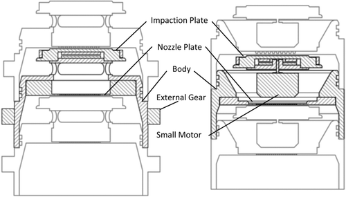
Thus, a second generation MOUDI was developed with small electric motors embedded in each stage with the impaction plates attached directly on the motor shafts, as shown in . Although the internal configuration is somewhat different between the MOUDI and 120 MOUDI-II (), the number of stages, the size and number of nozzles on each stage, and the jet-to-plate distances of each stage have been kept the same between the two versions.
Three 120 MOUDI-IIs were used in a 32-month program to sample ambient atmospheric aerosols at a variety of industrial and urban locations in Minnesota. To enable any impactor to sample at any location at any time and provide particle size distributions and concentrations that can be compared, it is necessary that the particle collection characteristics for three impactors be the same. To check this, the three impactors were also evaluated in a side-by-side comparison program in a laboratory dust chamber.
Finally, the long-term sampling capability was demonstrated by a background-sampling program at an urban (Minneapolis, MN, USA), light industrial (Duluth, MN, USA), and pristine wilderness (Ely, MN, USA) site. The 120 MOUDI-IIs were run in Minneapolis for six sampling periods, from 140 to 168 h for each sample period, in Duluth for 12 sampling periods, from 98 to 168 h for each sample period and in Ely for 6 sampling periods, from 70 to 168 h for each sample period.
120 MOUDI-II DESIGN
The design of the stage nozzle plates and their relation to the impaction plates of the 120 MOUDI-II is the same as the original MOUDI, as tabulated in . Thus, the particle collection efficiency curves for the two impactors should be the same (Marple et al. Citation1991). The major differences are in the mechanical design and additional features that have been incorporated into the 120 MOUDI-II impactors. shows schematics of impactor stages in the original MOUDI () and in the 120 MOUDI-II (). The main difference is that the 120 MOUDI-II has a miniature electric motor chamber located about 0.2 inches above the upper surface of the nozzle plate. Considering that stage 2 is the first stage to be affected by an electric motor chamber and the nozzles on this stage are 0.1495 inches in diameter with a 0.035 in × 45° chamfer on the inlet, it is not expected that the flow field through the nozzles will be affected by the presence of the electric motor chamber. All subsequent stages have smaller nozzles and should be even less affected by the presence of the chamber. The flow path is cleaner from impaction plate to nozzle plate of the next stage in the 120 MOUDI-II than in the original MOUDI since the flow does not have make an 180° turn. Thus, particle losses are expected to be slightly less in the120 MOUDI-II, but no tests were performed to confirm this. Also, it has been observed that the presence of the motor chamber has not increased particle inter-stage losses. In addition, a cover has been placed over the motors, with only the shaft exposed, to isolate as much as possible the motor from the flow through the impactor.
TABLE 1 120 MOUDI-II design and operating parameters
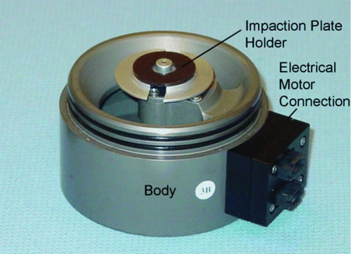
Impaction plates are mounted directly to the output shafts of the electric motors in each stage of the 120 MOUDI-II as shown in . shows a stage with a motor installed (with the impaction plate holder pressed on the motor shaft). Motors are miniature stepper motors (Minebea Electronics Co. Ltd., Japan) and are embedded in a chamber located in the center of the stage body. The impaction plate holder is glued onto the motor shaft to a specific distance from the motor flange to the impaction plate holder bottom surface in order to obtain the desired jet to impaction plate distance for each stage. Electrical leads are fed from the motor to the outside of the stage by an internal passage in the motor chamber support arm and terminate at a custom-made connector.
FIG. 2 The 120 MOUDI-II impactor stage with motor.
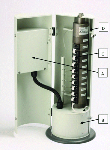
All stage motors are connected electrically in a daisy-chain fashion from top to bottom using ribbon cables as shown in . The last motor is connected to a programmable stepper motor driver, which is connected to the main controller. shows the MOUDI-II housing in the open position. The main cabinet of the MOUDI-II contains the controller for the impactor, which has a user interface display with touch screen capability and a membrane keypad. Firmware in the controller allows the user to program the operation of the 120 MOUDI-II sampler and communicates with the sensor board and the motor driver. The absolute pressures at six stages of the impactor and the cabinet temperature are automatically measured, data logged and stored in the volatile memory of the controller during a sample run. The controller also commands a signal to start and stop the pump through a custom relay box connected to the sampling pump. Finally, the controller also has an Ethernet port that allows the user to perform all the instrument control functions from a remote computer in a computer network to which the controller is connected.
FIG. 3 The 120 MOUDI-II with cabinet open A: location of main controller; B: location of stepmotor driver; C: daisy-chained ribbon cables; D: 10 stage impactor.
LABORATORY EVALUATION OF THE 120 MOUDI-II
To evaluate the precision of the 120 MOUDI-II, a test program was initiated where all three units were put in an aerosol chamber where they would be sampling the same aerosol to determine if they would provide the same mass size distribution measurement.
For the comparison test, three 120 MOUDI-II cascade impactors (model 120 MOUDI™-II, MSP Corp., Shoreview, MN, USA) designated as A, B, and C corresponding to serial numbers MDI-120R-006, MDI-120R-007, and MDI-120R-008, respectively, were provided by the Natural Resources Research Institute (NRRI) for side-by-side comparison testing. An aerosol test chamber (Marple and Rubow Citation1983) was used to provide uniform aerosol concentrations to the impactors. The chamber was designed specifically to provide a quiescent atmosphere in which the entire instruments being evaluated can be exposed to a given aerosol. Because of the relatively large chamber floor area of 1.1 m2, all three 120 MOUDI-IIs could easily be placed in the chamber for evaluation. The chamber was previously evaluated for spatial uniformity and temporal stability of the aerosol concentration in the test section using monodisperse and polydisperse aerosols. The maximum spatial aerosol concentration variation was found to be less than the measurement uncertainly of ±4% and the temporal uniformity was found to be constant as a function of time. A high-output polydisperse aerosol generator (Marple et al. Citation2006) was used to generate a polydisperse aerosol from a solution of 5% oleic acid tagged with an uranine dye tracer in methanol. After the solution was aerosolized, it was dried using dilution air and brought to electrostatic charge equilibrium using a Po 210 radioactive neutralizer. The conditioned aerosol was introduced into the top of the chamber and uniformly distributed to the 120 MOUDI-IIs below in the chamber test section. The solution concentration was selected to provide an aerosol mode of about 2 μm and a geometric standard deviation (GSD) of approximately 2.2 so that particles would be collected throughout most of the stages of the 120 MOUDI-II.
TABLE 2 Average 120 MOUDI-II total, PM10 and PM2.5 mass concentrations for winter and summer seasons by location
Five 120 MOUDI-II comparison tests were performed in the aerosol test chamber. For each test the stages of the three 120 MOUDI-IIs stages were loaded with aluminum substrates and Type A/E glass fiber filters were placed in the after-filter stages. The 120 MOUDI-IIs were then placed in the test chamber where the mass flow meters were connected downstream of the 120 MOUDI-IIs followed by vacuum pumps using 3/8 inch I.D. Tygon® tubing. The inlet of each MOUDI was connected to a Rockwell dry gas meter and the mass flow meters were calibrated to 30.0 ± 0.3 L/min. Following the flow calibrations, the impactor inlets were covered with sheets of cardboard to prevent aerosol from settling into the 120 MOUDI-IIs while the aerosol in the chamber was stabilizing. The chamber was then sealed, the blower turned on and aerosol was introduced into it. After 20 min, which was sufficient time to allow the aerosol to stabilize, the cardboard was removed from the 120 MOUDI-II inlets and the pumps were turned on for a sampling period of 5 min. Mass concentrations in the chamber ranged from approximately 150 to 200 mg/m3 during sampling. The 120 MOUDI-IIs were then removed from the chamber and each of the substrates and after-filters were placed in known amounts of 0.001 N NaOH. A Turner model 450 fluorometer was used to determine the relative amounts of dye in the wash solution (Marple et al. Citation2003). The fluorometer was calibrated before each test and a linear fit to the data consistently gave a coefficient of determination, R 2, of 0.999. Fluorometric analysis of the substrates and after-filters were then used to determine the relative amounts of dye in the wash solutions. By knowing the amount of dye in the wash solutions and the wash solution volumes, the mass collected on each stage could be determined (Marple et al. Citation1991). From the mass data, the size distributions for each of the 120 MOUDI-IIs were constructed and the differences between the size distributions determined.
FIELD RELIABILITY EVALUATION OF THE 120 MOUDI-II
To test the 120 MOUDI-II ability to run for long periods of time (a week or more), the three 120 MOUDI-IIs that had gone through the comparison tests were used in a background study at three locations, representing three levels of particulate concentration: Minneapolis, MN representing an urban site, Duluth, MN representing a light industrial site and Ely, MN, representing a rural, pristine site.
Before each run the impactors were cleaned thoroughly, including an entire wipe-down inside and out using ethyl alcohol. The 120 MOUDI-II nozzle plates were also soaked in an ethyl alcohol bath in the laboratory for a minimum of 4 h. All impaction plates and rings were also cleaned with ethyl alcohol. A small amount of silicon grease was placed on the O-ring between each impactor stage during re-assembly.
Postcollection substrates were carefully removed from the 120 MOUDI-IIs and placed back into their dedicated (labeled) petri-slides and cover. Substrates were conditioned in a desiccator for a minimum of 12 h before the final gravimetric weighing.
RESULTS
For the laboratory experimental evaluation, the program DistFit™ (DistFit™ Users Guide V. 2.0 Citation2009) was used to plot the mass histograms and to fit the data assuming log-normal distributions. The mass median aerodynamic diameters (MMAD) and GSD were determined using DistFit™ and the averages were determined across five simultaneous measurements and pooled standard deviations were calculated. The standard deviations were found to be low for both the MMADs and GSDs. When comparing the average MMADs and GSDs for the 120 MOUDI-IIs A, B, and C, they were all the same within the experimental uncertainties. The overall average MMAD and GSD were found to be 2.01 ± 0.03 μm and 2.28 ± 0.03, respectively.
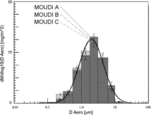
shows the mass concentration histograms with error bars indicating ± one standard deviation of 120 MOUDI-IIs A, B, and C for the five tests, along with the DistFit™ determined curve fits to the data. The total mass for each 120 MOUDI-II was normalized to the average of the total mass of the three 120 MOUDI-IIs for comparison. The results show good agreement between impactor mass distributions with the curve fits being nearly identical.
FIG. 4 Average normalized mass distribution comparison between 120 MOUDI-IIs A, B, and C (error bars indicate ±1 standard deviation).
For the field reliability evaluation at the three background sampling site locations, the 120 MOUDI-II impactors were operated for a total of 3,134 h. In all of these runs the 120 MOUDI-IIs ran unattended for the whole sample period without a failure.
Most sample run times were 5–7 days (120–168 consecutive hours of operation). During this time, over 5,500 cubic meters of air was sampled. Particulate matter mass concentration ranges varied from 3.80–14.23 μg/m3, 4.10–14.11 μg/m3, and 4.98–19.23 μg/m3.
shows the mass concentrations of Total (sum of all the MOUDI-II stages), PM10, and PM2.5 and shows the particle size distributions at the three sites (Minneapolis, Duluth, and Ely) for winter and summer seasons. Three year averages (2009–2011) reported by the Minnesota Pollution Control Agency (MPCA) for PM2.5 in Minneapolis and Duluth were 9.5 and 5.8 μg/m3, respectively (MPCA Citation2013). These mass concentrations compare well with the PM2.5 averages determined by the 120 MOUDI-IIs in the 32-month study at Minneapolis, 9.73 μg/m3 and Duluth, 5.21 μg/m3.
FIG. 5 Gravimetric mass distributions for averaged size-fractionated particulate matter at three background sites. The horizontal scale represents 120 MOUDI-II stage cut sizes based on aerodynamic diameter, whereas the vertical scale represents mass concentrations (μg/m3). Modeled distribution curve generated by the curve-fitting function in DistFit™ (Citation2009).
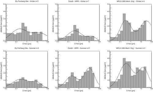
illustrates the DistFit™ generated mass distributions obtained from the three background sampling sites. The data for each site was averaged and plotted by season (winter, summer). Despite the differences in environmental conditions (Minneapolis—urban; Duluth—light industrial; Ely—rural, pristine), all plots illustrate a bimodal distribution of size-fractionated particulate matter. A cursory inspection of the plots indicates that, as anticipated, Minneapolis has the highest mass of aerosol particulate matter during both summer and winter seasons. Of notable interest, Ely shows higher concentrations than may be expected for a pristine background site when compared to the light industrial and urban sites of Duluth and Minneapolis, but this may be due to the sampling height being at ground level surrounded by trees at Ely compared to the high roof top sampling at the other two sites.
CONCLUSIONS
Three 120 MOUDI-II cascade impactors were collocated in an aerosol test chamber and evaluated to determine if differences existed between them as measured by their MMADs and GSDs when sampling the same polydisperse aerosol. The test aerosol was oleic acid tagged with uranine dye. Fluorometric analysis of the collected aerosols was used to determine the mass of particles collected on the stages of the 120 MOUDI-IIs. Five replicate tests were performed and DistFit™ was used to construct histograms from the size distribution data and to fit the data to log-normal distributions. The resulting MMADs and GSDs of the three 120 MOUDI-IIs were then compared to determine if there were measurable differences between them. The results indicated that the average MMADs and GSDs were nearly identical for the three 120 MOUDI-IIs and within the experimental uncertainties.
Effectiveness of using the 120 MOUDI-II for long-term particulate matter sampling, has been tested, and it has been shown that the 120 MOUDI-II is a precision instrument capable of sampling consistently, reliably, and for long intervals (up to one week), both in winter and summer time.
The enhanced ability to sample for long intervals allows the user to differentiate minute differences in size fractionated particulate matter concentrations that may be attributable to local industrial sources.
REFERENCES
- Andersen , A. A. 1958 . A New Sampler for the Collection, Sizing and Enumeration of Viable Particles . J. Bact. , 76 : 471 – 484 .
- Berner , A. , Lürzer , C. , Pohl , F. , Preining , O. and Wagner , P. 1979 . The Size Distribution of the Urban Aerosol in Vienna . Sci. Tot. Envir., , 13 : 245 – 261 .
- Chaun , R. L. 1970 . An Instrument for the Direct Measurement of Particulate Mass . Aerosol Sci., , 1 : 111 – 114 .
- DistFit™ and Users Guide V. 2.0 . 2009 . Forest Lake, MN : Chimera Technologies Inc. .
- Hering , S. V. , Flagan , R. C. and Friedlander , S. K. 1978 . Design and Evaluation of a New Low Pressure Impactor . Environ. Sci. Technol., , 12 : 667 – 673 .
- Keskinen , J. , Pietarinen , K. and Lehtimäki , M. 1992 . Electrical Low Pressure Impactor . J. Aerosol Sci., , 23 : 353 – 360 .
- Marple , V. A. 2004 . History of Impactors-The First 110 Years . Aerosol Sci. and Technol., , 38 : 247 – 292 .
- Marple , V. A. , Olson , B. A. and Santhanakrishnan , K. 2006 . Rapid Check of Cascade Impactor Cut-Sizes using a Polydisperse Challenge Aerosol Calibration Method . Aerosol Sci. and Technol., , 40 : 1064 – 1070 .
- Marple , V. A. , Olson , B. A. , Santhanakrishnan , K. and Mitchell , J. P. 2003 . Next Generation Pharmaceutical Impactor (A New Impactor for Pharmaceutical Inhaler Testing) – Part II: Archival Calibration . J. Aerosol Med., , 16 ( 3 ) : 301 – 324 .
- Marple , V. A. and Rubow , K. L. 1983 . An Aerosol Chamber for Instrument Evaluation and Calibration . Am. Ind. Hyg. Assoc. J., , 44 ( 5 ) : 361 – 367 .
- Marple , V. A. , Rubow , K. L. and Behm , S. M. 1991 . A Microorifice Uniform Deposit Impactor (MOUDI): Description, Calibration and Use . Aerosol Sci. Technol., , 14 : 434 – 446 .
- May , K. R. 1945 . The Cascade Impactor: An Instrument for Sampling Coarse Aerosols . J. Sci. Instr., , 22 : 187 – 195 .
- Mercer , T. T. , Tillery , M. T. and Newtorn , G. J. 1970 . A Multi-Stage Low Flow Rate Cascade Impactor . J. Aerosol Sci., , 1 : 9 – 15 .
- Minnesota Pollution Control Agency (MPCA) . 2013 . Annual Air Monitoring Network Plan for Minnesota – 2013. Doc. No. aq10–07a . : 49 Minnesota Pollution Control Agency, St. Paul, Minnesota. Available at: www.pca.state.mn.us/air/monitoringnetwork.html
- Pilat , M. J. , Ensor , D. S. and Bosch , J. C. 1970 . Source Test Cascade Impactor . Atmos. Environ., , 4 : 671 – 679 .