Abstract
Measurement of fine particle emission from combustion sources is important to understand their health effects, and to develop emissions regulations. Dilution sampling is the most commonly used technique to measure particle number distribution because it simulates the mixing and cooling of combustion exhaust with atmospheric air, which drives nucleation and condensation of semi volatile material. Experiments suggest that the measured size distribution is dependent on the dilution ratio used and the tunnel design. In the present work, computational analysis using a large-eddy-simulation (LES) based model is performed to investigate the effect of tunnel flow and geometric parameters on H2SO4-H2O binary nucleation inside dilution tunnels. Model predictions suggest that the experimental trends are likely due to differences in the intensity of turbulent mixing inside the tunnels. It is found that the interaction of dilution air and combustion exhaust in the mixing layer greatly impacts the extent of nucleation. In general, a cross-flow interaction with enhanced turbulent mixing leads to greater number of nucleation-mode particles than an axial-flow interaction of combustion sample and dilution air.
Copyright 2014 American Association for Aerosol Research
1. INTRODUCTION
Most combustion systems emit fine particles into the atmosphere. These particles are generally composed of elemental carbon (soot), organic carbon (OC), and sulfates, if the fuel contains sulfur. Measurement of number and mass distributions of fine particles is important to understand their health effects, and to develop emissions regulations. Characterization of particle distribution and emission rate are important inputs for chemical transport models that simulate urban, regional, and global pollution.
Dilution sampling is the most commonly used technique to measure particle number and mass distributions because it simulates the rapid mixing and cooling of hot combustion gas with the cold atmospheric air. During this mixing, many different aerosol microphysical processes such as formation of new particles via nucleation and condensation/evaporation of gas-phase species alter the particle emissions. The main objective of dilution sampling is to mimic these processes in a well-controlled laboratory environment. According to design requirement established by Hildemann et al. (Citation1989), a dilution tunnel should simulate atmospheric dilution process, provide adequate residence time for aerosol processes to occur, and minimize contamination and sampling losses. Many different designs of dilution tunnels, that differ in their size, flow geometry, ease of portability, are available (Hildemann et al. Citation1989; Chan et al. Citation1998; Lyyranen et al. Citation2004; Lipsky and Robinson Citation2005; Yoon et al. Citation2005; Li et al. Citation2011). There is a strong evidence that the measured particle distribution at the exit of the tunnel is dependent on the tunnel design (Lipsky and Robinson Citation2005), flow configuration (Lipsky and Robinson Citation2005), and dilution ratio (Khalek et al. Citation1999; Shi and Harrison Citation1999; Khalek et al. Citation2000; Wei et al. Citation2001a,Citationb). Lipsky and Robinson (Citation2005) performed measurements of particle distribution in exhaust gas of a diesel engine using two different dilution tunnels and found that the measured distribution is dependent on the tunnel design and dilution ratio (DR). They used a cross-flow dilution tunnel design of Hildemann et al. (Citation1989) and their newly developed axial-flow design. In the cross-flow tunnel, exhaust sample is introduced into cross flow of dilution air, while in the axial-flow tunnel, both exhaust sample and dilution air streams enter axially into the tunnel. The measurements were made for dilution ratios of 20 and 110. The measured distributions were very similar in the accumulation-mode but the DR 20 case for the cross-flow tunnel showed more particles in the nucleation-mode. In general, the cross-flow tunnel measurements indicated more particles in the nucleation mode compared to the axial-flow tunnel developed by Lipsky and Robinson (Citation2005). In diesel engine exhaust, it is very likely that the nucleation-mode particles appeared from H2SO4-H2O binary nucleation inside the tunnels, since the fuel contained high levels of sulfur. Other mechanisms of particle formation, however, cannot be ruled out. Since nucleation is driven by mixing of hot and cold streams, the tunnel design and flow conditions must play an important role in the final shape of the measured distribution (Khalek et al. Citation1999; Shi and Harrison Citation1999; Khalek et al. Citation2000; Wei et al. Citation2001a,Citationb; Lipsky and Robinson Citation2005).
Computational fluid dynamics (CFD) of aerosol dynamics in turbulent flows provides an important tool to better understand the effects of dilution and emissions. To date, these simulations have mostly been limited to simple flow configurations (Garmory and Mastorakos Citation2008; Das and Garrick Citation2010; Loeffler et al. Citation2011; Veroli and Rigopoulos Citation2011; Zhou and Chan Citation2011). There are only few examples of CFD analysis of aerosol dynamics in dilution tunnels. Pyykonen et al. (Citation2007) performed CFD simulations of nucleation of dibutylphthalate in a perforated tube diluter. It was found that the nucleation occurs in localized regions of the flow where high vapor concentration of dibutylphthalate is present at lower temperatures. Recently, Wang et al. (Citation2013) performed CFD simulations of the experimental tunnels used by Lipsky and Robinson (Citation2005). The experimental trends were well captured by the CFD model, however, the authors found that the differences in the level of nucleation between DR 20 and DR 110 of the cross-flow tunnel were primarily due to differences in the relative humidity of the dilution air. They assumed 10% relative humidity in the dilution air for DR 20 and 0% for DR 120. The differences between the two tunnels were attributed to different levels of turbulence. The authors identified the dilution rate of the exhaust sample as a potential unifying parameter to explain effect of flow field on nucleation inside the tunnels.
Experimental measurements (Khalek et al. Citation1999; Lipsky and Robinson Citation2005) and numerical simulations (Wang et al. Citation2013) suggest that it is difficult to control aerosol microphysics inside a dilution tunnel. Design of the tunnel and flow conditions play an important role in determining the characteristics of aerosol particles measured at the end of the tunnel. In the present work, we have performed CFD analysis to understand the role of flow configuration and tunnel geometry on nucleation inside the tunnels. A large-eddy-simulation (LES) based turbulent flow solver is coupled with aerosol dynamics equations in the presence of nucleation, condensation, and coagulation. First, the experimental cases of Lipsky and Robinson (Citation2005) are simulated to evaluate the model and to understand the causes for different number of nucleation mode particles observed in the measurements. Second, additional simulations are performed to systematically investigate the effect of dilution ratio, tunnel flow rate, and tunnel geometry, on nucleation inside the tunnels. This work is expected to elucidate the role of mixing and dilution in the formation of ultrafine particles (UFP) in combustion plumes, and provide guidance for development of dilution tunnels.
2 NUMERICAL FORMULATION
Simulations were performed using commercial CFD code CONVERGE (Richards et al. Citation2003). A fully-implicit time differencing PISO algorithm (Issa Citation1986) is used for velocity and pressure coupling. A second-order nonweighted central differencing scheme is used to approximate all spatial derivatives. However, in order to aid the numerical stability of the solution, the numerical scheme is switched to first-order upwind in the regions of the computational domain where the velocity or density fields become nonmonotonic (Richards et al. Citation2003). Additional details of numerical schemes available in CONVERGE can be obtained from Richards et al. (Citation2003). Large-eddy simulation (LES) technique is used for predictions of turbulence. The aerosol microphysics are incorporated into the code using operator splitting method. Details of numerical formulation for mass, momentum, energy, gas-phase species, and particle transport are provided in the online supplementary information (SI).
2.1 Aerosol Microphysics
To account for the aerosol microphysical processes of coagulation and condensation, TwO-Moment Aerosol Sectional (TOMAS) microphysics model of Adams and Seinfeld (Citation2002) is used. The TOMAS model solves for two independent moments of the aerosol size distribution for each size bin or category. The two moments are the aerosol number density, Nk, and the mass density, Mk, where k is the bin number. The number and mass distributions are discretized into 15 bins (B = 15). As discussed in Lee and Adams (Citation2012), mass quadrupling is assumed between neighboring bins, resulting in the smallest particle size of 0.65 nm and the largest particle size of 425 nm. More details of the aerosol formation of TOMAS can be found in Adams and Seinfeld (Citation2002), while the original numerical formulation (for cloud microphysics) is in Tzivion et al. (Citation1987, Citation1989). For the five-component aerosol considered in the present work, 90 transport equations (Equation (S9) in the SI), 15 for Nk and 75 for Mk, are solved. Binary nucleation of sulfuric acid and water is approximated using parameterization of Vehkamaki and Lehtinen (Citation2003). The parameterization is valid for temperatures up to 400 K.
Aerosol particles are assumed to be spherical for purpose of calculating condensation, and are formed of five components, elemental carbon (EC), water (H2O), sulphate (SO4), and two components of semivolatile organic carbon (OC). Coagulation is calculated assuming Brownian motion. Sulfuric acid is allowed to condense only below gas phase temperature of 350 K, as suggested by vapor-pressure correlation proposed by Ayers et al. (Citation1980). Water in the particle phase is calculated by assuming equilibrium with relative humidity in the gas phase. For the experimental data used in this work, Shrivastava et al. (Citation2006) was able to predict partitioning of the semivolatile organic carbon using a two-component OC model. Therefore, the two-component model is used in this work to predict condensation/evaporation of OC onto existing particles. Component 1 has molecular weight (MW) of 282 and saturation concentration of 1784 μg/m3, while component 2 has MW of 394 and saturation concentration of 8 μg/m3. Shrivastava et al. (Citation2006) allocated 58% of the total organic mass to component 1 and 42% to component 2. In the particle phase, partial vapor pressure of each organic component is calculated based on its mole fraction in the mixture of two components.
TABLE 1 Flow parameters and boundary conditions for the cross-flow and axial flow tunnels for dilution ratios of 20 and 110
3 COMPUTATIONAL SETUP
3.1 Tunnel Designs and Flow Configurations
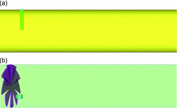
Two designs of dilution tunnels used by Lipsky and Robinson (Citation2005), a cross-flow design, and an axial-flow design, are considered. As shown in in the cross-flow design, the combustion sample is introduced into a cross flow of dilution air to promote mixing. For the axial-flow design, dilution air and combustion sample enter coaxially into the tunnel. For improving mixing of the two streams, a swirler-type mixing enhancer was installed slightly upstream of the sample inlet. Only a portion of the tunnels near the sample inlet are shown in . The lengths of the cross-flow and axial-flow tunnels are about 2.3 m and 0.9 m, respectively, while the diameters are 0.15 m and 0.11 m, respectively. The inner diameter of the sample tube is 0.011 m for both tunnels. The flow rates in the tunnels are such that the residence time (RT) based on the dilution air bulk flow rate is about 2.5 s for both tunnels. Two different dilution ratios (DR) of 20 and 110 are selected for computational analysis. In the experiments, dilution ratio was varied by changing the flow rate of the sample gas. Some key flow parameters of the two tunnels are provided in . Additional details are available in Lipsky and Robinson (Citation2005). Computational grids for the two tunnels and the grid sensitivity analysis are discussed in the SI.
3.2 Initial and Boundary Conditions
At the start of the simulations, the flow field was initialized with a zero velocity. The gas phase composition was initialized as pure air at temperature of 298 K, pressure of 1 bar, and a RH of 0%. The aerosol particle concentration was also initialized to zero.
The boundary conditions for mass, momentum, and energy equations are given in . Temperature of the sample pipe and tunnel were set to 514 K and 298 K, respectively. Dilution air enters the tunnel at a temperature of 298 K and with a RH of 10% for both tunnels. RH of dilution air was measured to be 10% in the experiments, which was near the detection limit of the instrument. Therefore, boundary condition for RH of dilution air involves some uncertainty. Velocity at the entrance of the tunnel is specified based on the experimental measurements of dilution air flow rate. The sample enters the tunnel at a temperature of 514 K and with a water mole fraction of 0.065. The sample velocity is set to obtain the target dilution ratio. The diesel fuel used in the experiments contained 500 ppm of sulfur on mass basis. The engine was run with an air-to-fuel ratio of 32. It is suggested in the literature that sulfur to SO3 conversion ratio is within 4–8% range (Vouitsis et al. Citation2005). In the present work, it is assumed that 8% of the fuel sulfur is converted into SO3, which is then assumed to instantly convert into H2SO4. Therefore, H2SO4 mass concentration of 2.32 μg/m3 at temperature of 514 K and pressure of 1 bar is specified in the sample. As will be discussed later, choice of an upper limit conversion ratio is justified because even with an 8% conversion ratio, tuning of the binary nucleation rate is required to match the total number concentration measured in the experiments. Mass concentrations of the two OC components in the exhaust sample are given in .
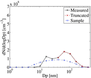
There are pre-existing particles in the sample flow, but unfortunately measurements of their number and size are not available as they were only made at the exit of the tunnel. Instead, their boundary conditions are specified by inferring from the output measurements. The measured aerosol number and mass distributions at the end of the tunnel contains elemental carbon (EC), organic carbon (OC), sulfate, and water, as discussed in Lipsky and Robinson (Citation2005) and Shrivastava et al. (Citation2006). Among these, OC is the dominant volatile fraction. It is, however, unlikely that the OC and sulfate will exist in the particle phase in the combustion sample. Hot combustion sample is likely to contain only EC in the particle phase, the distribution of which should be same for all dilution conditions. The measured distribution contains particles formed during the combustion process, as well as particles formed inside the dilution tunnel. Therefore, the measured distribution for DR 110 (case with less nucleation mode particles) was truncated below the second peak (40 nm) assuming that the particles above this size were primarily made of EC. The truncated distribution, however, is at the tunnel exit, and has gone through OC condensational growth inside the tunnel. Ideally, the truncated distribution should be evaporated to obtain EC distribution in the sample. But the size-dependent EC/OC ratio is not available from the experiments. Therefore, a number of EC distributions were specified in the sample and made to grow via condensational growth of gas-phase OC inside the tunnel until the grown distribution approximately matched the truncated distribution. The number distribution specified in the sample for all cases is shown in , along with measured and truncated distributions. Such an ad-hoc procedure underscores the importance of measuring EC distribution in the combustion sample for providing better boundary conditions for the models. A zero-gradient wall boundary condition is specified for the particles.
4 RESULTS AND DISCUSSION
4.1 Flow Field Inside the Experimental Tunnels
In the cross-flow tunnel, the interaction of sample with dilution air and subsequent mixing are strongly dependent on the relative velocities of the two streams. For DR 20, the sample flow velocity is 14.90 m/s, versus the dilution air bulk flow velocity of ∼1 m/s. As shown in , at DR 20 sample gas impinges on the tunnel wall leading to wall-induced mixing. At DR 110, the sample velocity is only 2.75 m/s and the cross flow of dilution air deflects the sample jet avoiding wall impingement. For DR 110, Reynolds number of sample jet is only 760 versus 4100 for DR 20. As will be discussed later, a lower Reynolds number for DR 110 leads to a thinner and less disturbed shear layer for DR 110 case, which has implications on nucleation.
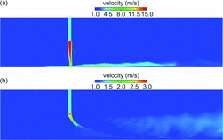
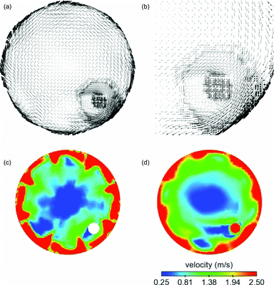
The axial-flow tunnel was operated at much lower flow rates than the cross-flow tunnel. The dilution air bulk flow velocity was only 0.25 m/s, resulting in a dilution air Reynolds number of only 2250 versus 9000 for the cross-flow tunnel. The sample flow velocity was 2.5 m/s for DR 20 and 0.47 m/s for DR 110, resulting in low Reynolds numbers (). For the axial-flow tunnel, it is, however, misleading to consider only the bulk flow velocity to analyze the interaction between the sample and the dilution air because the presence of swirler significantly perturbs the flow near the sample inlet. As shown in , after dilution air passes through the swirler, axial flow is converted into swirling flow with significantly higher velocities. a shows velocity vectors in the entire cross-section of the tunnel near the sample inlet, while b shows vectors in a smaller region near the sample inlet. It is clear that the axial velocity is converted into tangential velocity. c shows contours of velocity magnitude just downstream of the swirler, while d shows contours on a cross-section near the sample inlet. The magnitude of the swirling velocity is below 1.5 m/s (dark gray [red]) near the sample inlet, which is much higher than the bulk flow axial velocity.
4.2 Comparison of Measurements and Predictions of Particle Number Distributions
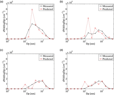
Comparison of the measured and predicted dilution-corrected particle number distributions (PND) for DR 20 and DR 110 of both tunnels is given in . As discussed in the SI, the predicted nucleation rate was multiplied by a factor of 25. It should be mentioned here that the present treatment of nucleation takes binary nucleation as its starting point. In the ambient atmosphere, it is well known that standard binary nucleation theory underpredicts observed nucleation rates (Weber et al. Citation1995, Citation1996, Citation1997). It has been suggested that various other species including ammonia (Napari et al. Citation2002), amines (Kurten et al. Citation2008), or organics (Zhang et al. Citation2004) participate with sulfuric acid and water in the nucleation process, but reliable theories are not yet available nor were suitable measurements of these other species. Therefore, it is possible that tuning of binary-nucleation rate accounts for both deficiencies in the binary-nucleation parameterization, and for unaccounted nucleation mechanisms. For the cross-flow tunnel, nucleation mode is predicted for both DR 20 and DR 110, while the nucleation mode was only measured for DR 20. For DR 20, the peak of the distribution lies near 25 nm in both measurements and predictions, indicating that the model is reasonably predicting the growth of the nucleated particles. The predicted distribution is slightly narrower than the measured distribution for DR 20. For DR 110, the predicted distribution is shifted to slightly lower sizes compared to the measurements. For the axial-flow tunnel, both measured and the predicted distributions exhibit a weaker nucleation mode compared to the cross-flow tunnel, as suggested by fewer particles below 20-nm size. The peak and the width of the predicted and measured distributions agree reasonably well. For all four cases presented in , the boundaries of the PND are predicted well, suggesting that the particle growth due to OC condensation is accurately captured by the model.
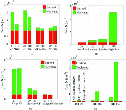
The measured and predicted total number concentration (N) for both tunnels are shown in a. In , total N given by the dark gray bars correspond to the EC particles specified in the undiluted hot combustion sample, and, therefore, does not depend on the conditions inside the dilution tunnel. For the cross-flow tunnel, the measured total N is 40% higher for DR 20 while the model predicts only 20% difference between two dilution ratios. This is because the model predicts a strong nucleation mode for DR 110 also, which was not observed in the measurements. For the axial-flow tunnel, the measured total N is higher by 6% for DR 20, while the predicted total N is lower by 12%. Between the two tunnels, the measurements suggest that the axial-flow tunnel produces lower number of new particles, a trend that is also well captured by the model. The differences in total N are primarily due to nucleation and not due to coagulation. Results presented in the article were obtained in the presence of coagulation, however, nearly same total N was observed in the absence of coagulation model. This is because the residence time in the experimental tunnels is only 2.5 s, which is very short time for coagulation to take place.
4.3 Effect of Flow on Particle Nucleation Inside the Experimental Tunnels
shows the instantaneous nucleation rate for DR 20 and DR 110 cases of the cross-flow tunnel, and DR 20 case of the axial-flow tunnel. DR 110 case for the axial-flow tunnel is not shown because it had a similar distribution as for the DR 20 case. For the cross-flow tunnel, the nucleation rate is shown on a plane that passes through the axes of the sample pipe and tunnel. For the axial-flow tunnel, the sample pipe is off center, so the nucleation rate is shown on a plane that passes through the center-axis of sample pipe, as well as on three tunnel cross-sections with locations marked on c. Only regions near the sample inlet are shown in where the nucleation occurs (no nucleation was predicted in the downstream regions). For DR 20 of the cross-flow tunnel, nucleation occurs near the tunnel wall and in the downwind region of the sample jet. The upstream shear layer (mixing region at the jet periphery) is much thinner, limiting the size of the nucleation zone. A larger mixing region is established downstream of the sample jet, creating a much bigger zone for nucleation. Splashing of high velocity sample jet from the tunnel wall and its interaction with the cross-flow of dilution air is responsible for a larger nucleation zone downwind of the jet. For DR 110, sample jet with relatively lower momentum is deflected by the dilution air such that the sample does not impinge on the tunnel wall. Nucleation again occurs only in the shear layer, but for this case, the shear layer is much thinner on both upwind and downwind sides of the sample jet. Although the peak nucleation rate is similar for both dilution ratios, a smaller nucleation zone for DR 110 leads to an overall lower total N at the tunnel exit (a).
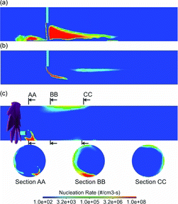
For the axial-flow tunnel, a tangential velocity is imparted to the sample jet due to swirling action of the dilution air. Therefore, although the dilution air and sample streams enter the tunnel coaxially, due to presence of the swirler the sample is exposed to a swirling cross flow of the dilution air. A complex mixing zone is established near the sample inlet and close to the wall of the tunnel. The peak nucleation rate is similar to the cross-flow tunnel, but the volume over which the peak nucleation rate is achieved is relatively small, leading to overall lower total N at the tunnel exit.
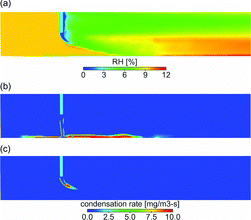
The H2SO4 undergoes gas-particle conversion via either nucleation or condensation, both of which are favored at lower temperatures. As discussed in Vehkamaki and Lehtinen (Citation2003), the H2SO4-H2O binary nucleation rate changes by almost ten orders of magnitude when temperature is changed from 325 K to 290 K at RH = 10% and H2SO4 molecular concentration of 1011/cm3. Therefore, the nucleation rate depends very strongly on the local H2SO4 saturation ratio and the RH. In the unmixed sample jet, the concentration of H2SO4 is highest, however, the H2SO4 saturation ratio and RH are lowest. As shown in , RH is higher at the periphery of the jet inside the shear layer. A combination of lower temperature, higher RH, and H2SO4 saturation ratio leads to a higher nucleation rate in the shear layer (). On the other hand, the condensation rate of H2SO4 is larger inside the core of the jet, where higher concentrations of H2SO4 and particles coexist (b and c). If the shear layer is more turbulent and wider, more H2SO4 becomes available for nucleation, as for DR 20 case of the cross flow tunnel. If the shear layer is thin and less disturbed, more H2SO4 is lost to condensation inside the jet.
4.4 Effect of Tunnel Flow Rate on Particle Nucleation
A detailed analysis of nucleation inside the tunnels revealed that the formation of new particles is influenced by the mixing in the shear layer, which further depends on the strengths of the sample and dilution air streams. In experiments, dilution ratio was varied by changing the flow rate of the sample. For example, to change DR from 20 to 110 in the cross-flow tunnel, the flow velocity of the sample was reduced from 14.9 m/s to 2.75 m/s. One could also change the flow rate of the dilution air to vary the dilution ratio, which would result in a entirely different flow rate in the tunnel. Therefore, in order to understand the effect of tunnel flow rate, simulations are performed by changing the flow rate of the dilution air for the cross-flow tunnel. First, the sample velocity is fixed at 14.9 m/s and the dilution air velocity is set to 5.46 m/s to obtain dilution ratio of 110. Second, the sample velocity is kept at 2.75 m/s and the dilution air velocity is set to 0.18 m/s to obtain dilution ratio of 20.
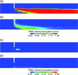
shows thespatial distribution of nucleation rate and root-mean-squared (RMS) velocity fluctuations in the tunnel for the high-flow DR 110 and the low-flow DR 20 cases. For the high-flow DR 110 case, both the sample and the dilution air streams have high flow velocities leading to a much disturbed and wider shear layer, as indicated by high RMS velocity fluctuations. A large number of new particles are formed in a much bigger nucleation zone. For the low-flow DR 20 case, the peak RMS velocity fluctuations and nucleation rate are lower, and the nucleation zone is limited to a very small region near the sample inlet. The dilution-corrected total N for the new and the baseline cases are shown in b. A correlation is observed between the flow velocity and the total N. The fewest new particles were formed for the low-flow DR 20 case, the highest number for the high-flow DR 110 case, while the baseline cases fall in-between these two cases. The predictions, therefore, suggest that the extent of nucleation inside the tunnels is more sensitive to the flow rates at which a particular dilution ratio is obtained, rather than the dilution ratio itself.
4.5 Effect of Tunnel Geometry on Particle Nucleation
As discussed previously, the two experimental tunnels were operated at different flow rates. For a given dilution ratio, flow rate in the axial-flow tunnel was much lower than the cross-flow tunnel. Therefore, in order to compare the two tunnels for the same dilution ratio obtained with the same flow rates, the size of the axial-flow tunnel was increased to match the size of the cross-flow tunnel. The modified tunnel is referred to here as the “large axial-flow” tunnel. In the large axial-flow tunnel, the swirler size was increased to fit the larger size tunnel. a shows contours of nucleation rate for the large axial-flow tunnel on a plane that passes through the axis of the sample pipe. Compared to the experimental axial-flow tunnel, nucleation occurs over a much larger region in the large axial-flow tunnel. As shown in c, the large axial-flow tunnel produced three times more particles than the cross-flow tunnel, and five times more particles that the experimental axial-flow tunnel (a). For the same flow rate, the large axial-flow tunnel produces more particles compared to the cross-flow tunnel due to the presence of a swirler. b shows velocity contours at different cross-sections of the tunnel. Although the bulk flow velocity upstream of the swirler is 1.0 m/s, which is the same as for the cross-flow tunnel, the peak velocity immediately downstream of the swirler is almost 10 m/s. Near the sample inlet, dilution air velocity is close to 5 m/s, leading to increased level of mixing of the sample with the dilution air, and creating favorable environment for nucleation.
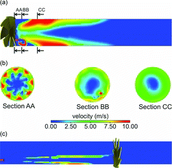
Since mixing caused by the swirler gives rise to more nucleation in the large axial-flow tunnel, another tunnel design is created in which, the swirler is moved downstream. The swirler is kept in the tunnel to mix particles after the nucleation is completed, hence, this tunnel design is referred to here as the “large axial-flow after-mixing” tunnel. If the swirler is removed from the tunnel, the gas at the exit of the tunnel will be only partially mixed, making it difficult to install sampling probes in the measurements. It should, however, be mentioned that such a design may not be favorable for measurements due to possibility of increased particle loss by deposition. Large surface area of the swirlier provides a sink for depositional loss, especially for small particles. In the present simulations, the depositional losses, that depend on the surface area and turbulence, are not taken into account, therefore, the distribution at the end of the tunnel is purely a consequence of the aerosol microphysics in the gas phase. c shows contours of nucleation for DR 20 of the large axial-flow tunnel with after-mixing. Significant nucleation is observed at some distance away from the sample inlet due to high velocity of the sample (14.9 m/s). Since there is no cross or swirling flow in this case, the shear layer is thin, limiting nucleation to a narrow region at the periphery of the jet. The total N for the large axial-flow tunnel with after-mixing is much lower as shown in c.
4.6 Sensitivity of Critical Trends to RH of Dilution Air
The binary nucleation of H2SO4-H2O depends strongly on the local RH of the mixture. The dilution air RH was measured to be 10% (at 298 K), which was close to the lower limit of the RH instrument used in the experiments. The binary nucleation rate also behaves nonlinearly for low RH, especially for RH below 20% (Vehkamaki and Lehtinen Citation2003). In order to investigate the dependence of some critical trends in total N on RH of dilution air, three cases that represent low, intermediate, and high level of nucleation in the tunnels are selected. These cases are, DR 20 case for the large axial-flow tunnel with after-mixing (total N = 8.0 × 10⁷[cm− 3]), DR 20 baseline case for the cross-flow tunnel (total N = 2.1×10⁸[cm− 3]), and DR 110 high-low case for the cross-flow tunnel (total N = 1.23 × 10⁹[cm− 3]). d shows comparison of the total N for RH of 5%, 10%, and 15%. Qualitatively, for all three values of RH, the DR 20 case of the large axial-flow tunnel with after-mixing produces the smallest, and the DR 110 high-flow case of the cross-flow tunnel produces the largest number of new particles. But the quantitative difference in the total N depends on the RH of the dilution air. For 5% RH, based on total number of particles, DR 110 high-flow case produces 80% more and DR 20 case of the large-axial flow tunnel with after mixing produces 22% less number of particles compared to the DR 20 baseline case of the cross-flow tunnel. The percentage changes in total N are +485% and −58% for 10% RH, and 683% and −83% for 15% RH. Therefore, for the present work, the flow conditions inside the tunnel have much greater influence on nucleation at higher RH of the dilution air. It should be mentioned here that the percentage changes in total particle numbers predicted by the model are valid only for the binary nucleation scheme used in the present work.
5 SUMMARY AND CONCLUSIONS
A large-eddy simulation (LES) based turbulent flow solver is coupled with aerosol dynamics equations in the presence of nucleation, condensation, and coagulation. Simulations are performed to investigate the effects of dilution ratio, tunnel flow rate, and tunnel geometry on H2SO4-H2O binary nucleation. The results presented in this article apply only to combustion exhaust that contains levels of sulfur adequate for binary nucleation. It is found that both the geometric design and flow conditions influence aerosol microphysics inside the dilution tunnels. A tunnel can be designed either to minimize nucleation or to replicate dilution of combustion gas in the atmosphere, where the latter is more difficult to control with consistency. Therefore, the objectives of dilution sampling should be clearly defined before designing a tunnel, since the measured distribution at the tunnel exit may or may not represent distribution emitted by the combustion source. Specifically, following main conclusions could be drawn from this work:
The LES model provided reasonably good predictions of particle evolution inside the tunnels for the binary nucleation scheme used. It is evident that nucleation is highly dependent on mixing characteristics of combustion sample and dilution air. Therefore, a zero-dimensional model may not be sufficient for predictions of aerosol microphysics in a turbulent and heterogeneous environment.
Nucleation occurs primarily in the shear layer where the hot combustion sample mixes with the cold dilution air resulting in regions of high RH and H2SO4 supersaturation. Extent of nucleation inside the tunnel correlates with the root-mean-squared (RMS) velocity fluctuations and width of the shear layer.
The use of bulk flow velocity and overall dilution ratio are not good measures of dilution air and sample mixing, and its eventual impact on nucleation. For given chemical and physical states of the sample and the dilution air, the important flow factors that control the extent of nucleation are the magnitude and direction of the dilution air velocity relative to the sample jet. Cross-flow configuration produces more particles than the axial-flow configuration. In the presence of mixing enhancers such as a swirler, the determination of flow configuration should be made based on the velocity field at the sample inlet, and not based on the direction of bulk flow in the tunnel.
When the tunnel is operated in a true parallel/axial flow configuration as in the case of large axial-flow tunnel with after-mixing, condensation of H2SO4 onto existing particles inside the core of the jet dominates, limiting nucleation to a thinner region. Therefore, if the objective is to reduce nucleation, a cross-flow interaction of the dilution air and sample should be avoided. However, installing mixing enhancers downstream of the sample inlet will likely increase particles losses.
As also pointed out by other researchers, nucleation inside the tunnel is highly sensitive to the RH of the dilution air. But for the range of RH considered here, the qualitative trends of the impact of tunnel flow and design parameters on nucleation do not change. Based on the simulations performed in the present work, flow parameters have greater impact on nucleation at higher RH. It is recommended that RH should be controlled within tight tolerances from test-to-test in the experiments.
ACKNOWLEDGMENTS
The authors express their appreciation to Convergent Science, Inc., for providing licenses of the CONVERGE code, and in particular, to Dr. Eric Pomranning and Keith Richards for help with model implementation. The authors also thank Dr. Dan Westervelt of Carnegie Mellon University and Dr. Jeffrey Pierce of Colorado State University for technical discussion.
FUNDING
A portion of the computing time was provided by the National Science Foundation (NSF) TeraGrid under Grant No. ASC110028 through the Pittsburgh Supercomputing Center (PSC).
SUPPLEMENTAL MATERIAL
Supplemental data for this article can be accessed on the publisher's website.
JAST_2013_Supplemental.zip
Download Zip (318.9 KB)REFERENCES
- Adams, P.J., and Seinfeld, J.H. (2002). Predicting Global Aerosol Size Distributions in General Circulation Models. J. Geophys. Res., 107:19,4370–4392.
- Ayers, G.P., Gillett, R.W., and Gras, J.L. (1980). On the Vapor Pressure Pressure Sulfuric Acid. Geophys. Res. Lett., 7:433–436.
- Chan, S.H., Sun, J.H., and Low, S.C. (1998). A Compact Particulate Dilution Tunnel for the Characterization of Diesel Exhaust. Proc. Inst. Mech. Eng., 212:299–310.
- Das, S., and Garrick, S.C. (2010). The Effect of Turbulence on Nanoparticle Growth in Turbulent Reacting Jets. Phys. Fluids, 22:103303.
- Garmory, A., and Mastorakos, E. (2008). Aerosol Nucleation and Growth in a Turbulent Jet Using the Stochastic Fields Method. Chem. Eng. Sci., 63:4078–4089.
- Hildemann, L.M., Cass, G.R., and Markowski, G.R. (1989). A Dilution Stack Sampler for Collection of Organic Aerosol Emissions—Design, Characterization and Field Tests. J. Aerosol Sci. Technol., 10:193–204.
- Issa, R. (1986). Solution of the Implicitly Discretised Fluid Flow Equations by Operator-Splitting. J. Comput. Phys., 62:40–65.
- Khalek, I.A., Kittelson, D.B., and Brear, F. (1999). The Influence of Dilution Conditions on Diesel Exhaust Particle Size Distribution Measurements. SAE Technical Paper 1999-01-1142.
- Khalek, I.A., Kittelson, D.B., and Brear, F. (2000). Nanoparticle Growth During Dilution and Cooling of Diesel Exhaust: Experimental Investigation and Theoretical Assessment. SAE Technical Paper 2000-01-0515.
- Kurten, T., Loukonen, V., Vehkamaki, H., and Kulmala, M. (2008). Amines are Likely to Enhance Neutral and Ion-Induced Sulfuric Acid-Water Nucleation in the Atmosphere More Effectively Than Ammonia. Atmos. Chem. Phys., 8:4095–4103.
- Lee, Y.H., and Adams, P.J. (2012). A Fast and Efficient Version of the TwO-Moment Aerosol Sectional (TOMAS) Global Aerosol Microphysics Model. Aerosol Sci. Technol., 46:678–689.
- Li, X., Wang, S., Duan, L., Hao, J., and Long, Z. (2011). Design of a Compact Dilution Sampler for Stationary Combustion Sources. J. Air Waste Manage., 61:1124–1130.
- Lipsky, E.M., and Robinson, A.L. (2005). Design and Evaluation of a Portable Dilution Sampling System for Measuring Fine Particle Emissions From Combustion Systems. J. Aerosol Sci. Technol., 39:542–553.
- Loeffler, J., Das, S., and Garrick, S.C. (2011). Large Eddy Simulation of Titanium Dioxide Nanoparticle Formation and Growth in Turbulent Jets. J. Aerosol Sci. Technol., 45:616–628.
- Lyyranen, J., Jokiniemi, J., Kauppinen, E.I., Backman, U., and Vesala, H. (2004). Comparison of Different Dilution Methods for Measuring Diesel Particle Emissions. J. Aerosol Sci. Technol., 38:12–23.
- Napari, I., Noppel, M., Vehkamaki, H., and Kulmala, M. (2002). An Improved Model for Ternary Nucleation of Sulfuric Acid-Ammonia-Water. J. Chem. Phys., 116:4221–4227.
- Pyykonen, J., Miettinen, M., Sippula, O., Leskinen, A., Raunemaa, T., and Jokiniemi, J. (2007). Nucleation in a Perforated Tube Diluter. J. Aerosol Sci., 38:172–191.
- Richards, K., Senecal, P., and Pomraning, E. (2003). A Three-Dimensional Computational Fluid Dynamics Program for Transient or Steady State Flow with Complex Geometries. Convergent Science Inc. Convergent Science, Inc., Middleton, WI (version 1.4.1 ed.).
- Shi, J.P., and Harrison, R.M. (1999). Investigation of Ultra Fine Particle Formation During Diesel Exhaust Dilution. Environ. Sci. Technol., 33:3730–3736.
- Shrivastava, M.K., Stanier, C.O., and Robinson, A.L. (2006). Modeling Semi Volatile Organic Aerosol Mass Emissions from Combustion Systems. Environ. Sci. Technol., 40:2671–2677.
- Tzivion, S., Feingold, G., and Levin, Z. (1987). An Efficient Numerical Solution to the Stochastic Collection Equation. J. Atmos. Sci., 44:3139–3149.
- Tzivion, S., Feingold, G., and Levin, Z. (1989). The Evolution of Raindrop Spectra, Part II, Collisional Collection/Breakup and Evaporation in a Rainshaft. J. Atmos. Sci., 46:3312–3327.
- Vehkamaki, H.M. K., and Lehtinen, K.E. J. (2003). Modelling Binary Homogeneous Nucleation of Water-Sulfuric Acid Vapours: Parameterisation for High Temperature Emissions. Environ. Sci. Technol., 37:3392–3398.
- Veroli, G.Y. D., and Rigopoulos, S. (2011). Modeling of Aerosol Formation in a Turbulent Jet with the Transported Population Balance Equation-Probability Density Function Approach. Phys. Fluids, 23:043305.
- Vouitsis, V., Ntziachristos, L., and Samaras, Z. (2005). Modelling of Diesel Exhaust Aerosol During Laboratory Sampling. Atmos. Environ., 39:1335–1345.
- Wang, Y., Yang, B., Lipsky, E.M., Robinson, A.L., and Zhang, M. (2013). Analyses of Turbulent Flow Fields and Aerosol Dynamics of Diesel Engine Exhaust Inside Two Dilution Sampling Tunnels Using the CTAG Model. Environ. Sci. Technol., 47:889–898.
- Weber, R.J., Marti, J.J., McMurry, P.H., Eisele, F.L., Tanner, D.J., and Jefferson, A. (1996). Measured Atmospheric New Particle Formation Rates: Implications for Nucleation Mechanisms. Chem. Eng. Commun., 151:53–64.
- Weber, R.J., Marti, J.J., McMurry, P.H., Eisele, F.L., Tanner, D.J., and Jefferson, A. (1997). Measurements of New Particle Formation and Ultrafine Particle Growth Rates at a Clean Continental Site. J. Geophys. Res., 102:4375–4385.
- Weber, R.J., McMurry, P.H., Eisele, F.L., and Tanner, D.J. (1995). Measurement of Expected Nucleation Precursor Species and 3–500-nm Diameter Particles at Mauma Loa Observatory, Hawaii. J. Atmos. Sci., 52:2242–2257.
- Wei, Q., Kittelson, D.B., and Watts, W.F. (2001a). Single Stage Dilution Tunnel Design. SAE Technical Paper 2001-01-0201.
- Wei, Q., Kittelson, D.B., and Watts, W.F. (2001b). Single Stage Dilution Tunnel Performance. SAE Technical Paper 2001-01-0207.
- Yoon, Y.J., Cheevers, S., Jennings, S.G., and D’Dowd, C.D. (2005). Performance of a Century Dilution Chamber for Sampling 3–20 nm Particles. Aerosol Sci., 36:535–540.
- Zhang, R.Y., Suh, I., Zhao, J., Zhang, D., Fortner, E.C., Tie, X.X., et al. 2004). Atmospheric New Particle Formation Enhanced by Organic Acids. Science, 304:1487–1490.
- Zhou, K., and Chan, T.L. (2011). Simulation of Homogeneous Particle Nucleation in a Free Turbulent Jet. J. Aerosol Sci. Technol., 45:973–987.

