Abstract
A horizontal inlet was employed to improve the collection efficiency of a rectangular-slit-nozzle impactor. A numerical and experimental study of the collection efficiency of rectangular-slit-nozzle impactors, with either typical inlets or horizontal inlets, was conducted. In the comparison of typical inlet impactors and horizontal-inlet impactors, parameters such as the nozzle width, impaction plate width, nozzle-to-plate distance, and aerosol flow rate were held constant, and only the inlet shape was changed. A parametric study was conducted to examine the effects of the horizontal inlet dimensions on the collection efficiency of rectangular-slit-nozzle impactors. It was found that a horizontal inlet could reduce the square root of the Stokes number corresponding to the cutoff size from 0.77 to 0.60, compared with a typical inlet.
Copyright 2014 American Association for Aerosol Research
1. INTRODUCTION
Inertial impactors are used to sample atmospheric particles on the basis of aerodynamic particle size. The cutoff size of an inertial impactor is the particle size that corresponds to 50% collection efficiency. In an ideal impactor, particles that are larger than the cutoff size are mostly collected on the impaction plate, and those that are smaller than the cutoff size escape the impactor stage without being trapped.
Many efforts have been made to reduce the cutoff size of inertial impactors and increase their collection efficiency. The impactor collection efficiency has been found to be greatly influenced by several parameters, including the aerosol flow rate, the nozzle width, the nozzle throat length, and the nozzle-to-plate distance (Davies et al. Citation1951; Ranz and Wong Citation1952; Marple and Liu Citation1974; Rader and Marple Citation1985; Grinshpun et al. Citation2005). The cutoff size can be reduced by operating inertial impactors at low pressures (Hering et al. Citation1978; Marjamäki et al. Citation2000). The impactor collection efficiency has been found to increase with the gravitational force at low Reynolds numbers (Huang and Tsai Citation2001). The application of thermophoretic force or electrostatic force increases the impactor collection efficiency (Lee and Kim Citation2002; Vinchurkar et al. Citation2009). The effect of the impaction plate diameter on the collection efficiency of round-nozzle impactors has also been investigated (Huang and Tsai Citation2002). Impaction plates with shapes other than flat shapes have been employed to increase the collection efficiency of inertial impactors (Tsai and Cheng Citation1995). Elliptical concave curvatures have been found to be particularly effective in decreasing the cutoff size of inertial impactors and reducing particle bounce (Kim and Yook Citation2011; Kim et al. Citation2013).
Although many studies have been performed to improve impactor collection efficiency by changing the operating environment or altering the impactor geometry, few studies have examined the influence of the inlet design on the collection efficiency of inertial impactors. In this study, in an effort to reduce the cutoff size of rectangular-slit-nozzle impactors, a horizontal inlet was employed upstream of the acceleration nozzle to make the inflow of aerosol turn a 90° angle by increasing the concentration of particles near the centerline of a rectangular-slit-nozzle impactor. A parametric study was performed to investigate the effects of the dimensions of the horizontal inlet on the collection efficiency of the rectangular-slit-nozzle impactor.
2 NUMERICAL SIMULATION
displays a schematic diagram of a rectangular-slit-nozzle impactor. shows a typical inlet impactor, into which an aerosol is drawn from the top in the same direction as that of the flow acceleration. The nozzle width is denoted W, the nozzle throat length T, the nozzle-to-plate distance S, and the impaction plate width P. depicts the horizontal inlet impactor with the same parameters as those of a typical inlet impactor, except for the inlet design. Two parameters for the horizontal inlet design are considered, they are the inlet height, A, and the inlet width, B.
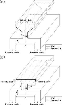
Airflow in a rectangular-slit-nozzle impactor was simulated using a computational fluid dynamics (CFD) code, ANSYS FLUENT v13.0. The ambient temperature and pressure were set to be 20°C and 101.3 kPa, respectively. Two-dimensional, steady, incompressible, and laminar flow conditions were assumed. Downward gravity was considered. The Reynolds number was calculated based on the nozzle width (W) and was set below 1600 to satisfy laminar flow conditions. The SIMPLE algorithm was used to couple pressure and velocity. The continuity, momentum, and energy equations were solved iteratively until the relative errors became lower than a convergence criterion of 10−6. The boundary conditions, i.e., the velocity-inlet at the inlet of the impactor, the pressure-outlet at the outlet of the impactor, the symmetry at the centerline, and no slip at all walls of the impactor, were set as illustrated in . The number of computational cells, determined by performing a grid test, ranged from approximately 30,000 to 55,000, depending on the nozzle width.
The discrete phase model (DPM) provided in the FLUENT software was employed to calculate the trajectories of particles in the impactor. The forces considered to act on the particles were the gravitational force and Stokes’ drag force with slip correction (FLUENT 6.3 User's Guide Citation2006). A statistical Lagrangian particle tracking approach was used to predict the collection efficiency of rectangular-slit--nozzle impactors, as in Kim et al. (Citation2013) and Lee et al. (Citation2014). Spherical particles of the same size and density were placed on the velocity-inlet plane at a constant spacing, and they were injected from the velocity inlet at the same velocity as the airflow velocity. The particles were assumed to be captured once they touched any wall in the impactor. The collection efficiency (η) was numerically estimated as follows:
[1]
In this equation, Np is the number of particles determined to be trapped on the impaction plate and Nin is the number of particles injected from the velocity-inlet plane. The particle density was set at 1050 kg/m3, based on the density of polystyrene latex (PSL) spheres.
3 EXPERIMENTAL VERIFICATION
The Stokes number (Stk) was calculated as follows:
[2]
In this equation, ρp is the particle density, dp is the particle size, Cc is the slip correction factor, U is the average airflow velocity at the nozzle, and μ is the viscosity of air. A PM2.5 rectangular-slit-nozzle impactor with a typical inlet, as shown in , was manufactured. The nozzle width was W = 1 mm, and the other dimensions were T/W = 2, S/W = 2, and P/W = 8. The nozzle span (L) was set to be 15 times the nozzle width, as in Kim et al. (Citation2013), to achieve two-dimensional airflow at the rectangular-slit nozzle. The square root of the Stokes number corresponding to the cutoff size is 0.77 for rectangular-slit-nozzle impactors (Hinds Citation1999). The average airflow velocity at the rectangular-slit-nozzle with W = 1 mm and L = 15 mm was determined to be U = 13.91 m/s, based on the impactor nozzle design guideline of (Stk50)1/2 = 0.77. For comparison, a rectangular-slit-nozzle impactor with the horizontal inlet shown in was manufactured. The nozzle width of the horizontal inlet impactor was also W = 1 mm, and the other dimensions were L/W = 15, T/W = 4, S/W = 2, P/W = 8, A/W = 1.5, and B/W = 3. For both the typical inlet impactor and the horizontal inlet impactor, the aerosol flow rate was Q = 12.5 L/min and the impaction plates were coated with vacuum grease to reduce particle bounce.
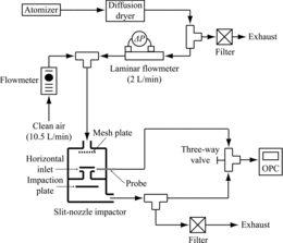
shows a schematic diagram of the experimental setup. PSL spheres (Thermo Scientific) with diameters of 1.3, 1.6, 1.8, 2.0, 2.5, 3.0, and 4.0 μm were used. The PSL particles were aerosolized using an atomizer (HCT model Atomizer 4810) and dried using a diffusion dryer filled with silica gel. The aerosol at a flow rate of 2.0 L/min was mixed with clean air at a flow rate of 10.5 L/min. Then, the diluted aerosol at a flow rate of 12.5 L/min was introduced into the rectangular-slit-nozzle impactor. The Reynolds number, based on the nozzle width, was 917. To uniformly distribute the particles upstream of the rectangular-slit-nozzle impactor with either a typical inlet or a horizontal inlet, a mesh plate was placed in front of the inlet of the impactor. The particle loss at the mesh plate was found to be negligible (Han Citation2007). An optical particle counter (OPC, HCT model PS-3030) with 10 bins in the size range between 0.3 μm and 10 μm was used to measure the particle number concentration upstream or downstream of the rectangular-slit-nozzle impactor. A probe was placed close to the entrance of the horizontal inlet to measure the upstream particle number concentration. The background particle number concentration was checked by atomizing DI water only, and it was found to be much lower than the particle number concentration measured by atomizing PSL spheres with DI water. Therefore, the background noise in the particle count was assumed to be negligible.
By considering particle capture on the surrounding inner walls other than the impaction plate, the impactor collection efficiency was evaluated as follows.
[3]
In this equation, Np is the number of particles collected on the impaction plate, Ns is the number of particles captured on the surrounding inner walls other than the impaction plate, Nin is the number of particles injected into the impactor, and Nout is the number of particles exhausted through the outlet of the impactor. Instead of experimentally determining Np, Ns, Nin, and Nout, particle number concentrations upstream and downstream of the impactor were measured with or without the impaction plate to estimate the ratios Ns/Nin and Nout/Nin for every particle size considered in the experiment
[4]
[5]
In these equations, Cup,without and Cdown,without are the upstream and downstream particle number concentrations measured without the impaction plate, and Cup,with and Cdown,with are the upstream and downstream particle number concentrations measured with the impaction plate.
4 RESULTS AND DISCUSSION
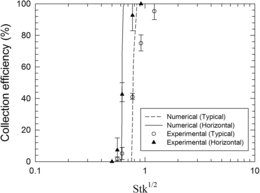
shows a comparison of the collection efficiency of rectangular-slit-nozzle impactors as determined from the experimental results and the numerical simulation. For both the typical inlet impactor and the horizontal inlet impactor, the nozzle width was W = 1 mm and the aerosol flow rate was Q = 12.5 L/min. The numerical data were in good agreement with the experimental results for both impactors; thus, the numerical approach used in this study was judged to be able to correctly predict the impactor collection efficiency. When the horizontal inlet was used, the cutoff size was smaller than the cutoff size of the typical inlet impactor. This clearly shows that the inlet design can influence the impactor collection efficiency. For reference, the fraction of particles deposited on the inner walls other than the impaction plate, that is, Ns/Nin, was estimated to be less than 10%.
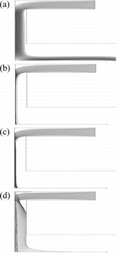
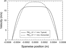
The particle-focusing behavior and the flow velocity in the nozzle were examined to assess the effect of the horizontal inlet on the reduction in the cutoff size. shows the simulated trajectories of particles in the horizontal inlet impactor at various values of the square root of the Stokes number when Q = 12.5 L/min, W = 1 mm, A/W = 1, B/W = 3, and T/W = 4. A comparison of and shows that the particles became more concentrated near the centerline as the Stokes number increased. When Stk1/2 was 0.80, some particles crossed the centerline but were still concentrated near the centerline, as shown in . However, when Stk1/2 was greater than 1.36, the particle beam became broad due to the high centrifugal force, and some particle loss at the nozzle throat was anticipated. This clearly shows that particles can be concentrated near the centerline in the nozzle, depending on the Stokes number when the horizontal inlet is used. shows a comparison of the spanwise flow velocity profile at the nozzle tip for the typical inlet impactor and the horizontal inlet impactor when Q = 12.5 L/min, W = 1 mm, A/W = 1, B/W = 3, and T/W = 4. The flow velocity in the region near the centerline was higher for the horizontal inlet impactor than for the typical inlet impactor. Therefore, when the horizontal inlet was employed, the particles concentrated near the centerline could be injected toward the impaction plate with greater inertia, resulting in a decrease in the cutoff size.
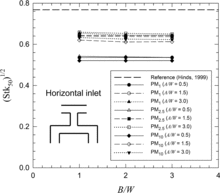
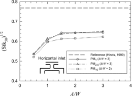
The collection efficiency of the horizontal inlet impactor was numerically investigated by varying the inlet design parameters B and A, as shown in and , respectively. The tested nozzle width was determined from EquationEquation (2)[2] with (Stk50)1/2 = 0.77, that is, W = 0.42 mm for a PM1 nozzle, W = 1.0 mm for a PM2.5 nozzle, and W = 3.9 mm for a PM10 nozzle. All these nozzles were assumed to be operated at a nozzle Reynolds number of approximately 920. By taking the practical size of an impactor into consideration, B/W was varied in the range from 1 to 3 and A/W was varied in the range from 0.5 to 3. displays the square root of the Stokes number corresponding to the cut-off size for B/W values of 1, 2, and 3. The effect of B/W on (Stk50)1/2 was insignificant for various A/W values. shows the variation of (Stk50)1/2 with the A/W ratio, with B/W fixed at 3 for all three horizontal inlet impactors with PM1, PM2.5, and PM10 nozzles. As the A/W ratio decreased for a fixed aerosol flow rate, the average flow velocity in the region of the horizontal inlet increased; at the same time, the maximum velocity at the nozzle increased. Because the average velocity in the region of the horizontal inlet is related to the particle-focusing behavior and the maximum velocity at the nozzle is related to the inertia of particles impacting the impaction plate, the cutoff size can be lowered by decreasing the A/W ratio. However, when A/W is greater than 1, (Stk50)1/2 is almost unchanged. Taking manufacturability into consideration, the dimensions of the horizontal inlet were selected to be A/W = 1 and B/W = 3 in the subsequent analyses.
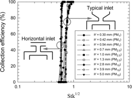
shows the numerically estimated collection efficiencies of rectangular-slit-nozzle impactors as a function of the square root of the Stokes number when the typical inlet or the horizontal inlet was employed. Three different nozzle widths were assumed for each PM1, PM2.5, or PM10 nozzle. The tested nozzle widths were determined from EquationEquation (2)[2] with (Stk50)1/2 = 0.77, that is, W = 0.30, 0.42, and 0.54 mm for the PM1 nozzles, W = 0.7, 1.0, and 1.3 mm for the PM2.5 nozzles, and W = 2.8, 3.9, and 5.0 mm for the PM10 nozzles. For both the typical inlet impactor and the horizontal inlet impactor, T/W = 4, S/W = 2, and P/W = 8. The dimensions of the horizontal inlet were fixed at A/W = 1 and B/W = 3. The nozzle Reynolds numbers ranged from approximately 450 to 1600. The collection efficiency curves for the rectangular-slit-nozzle impactors with different nozzle widths overlap one another for either the typical inlet impactor or the horizontal inlet impactor. When the typical inlet was replaced by the horizontal inlet, the value of (Stk50)1/2 was found to be reduced to 0.60. The reduction in the cutoff size of the rectangular-slit-nozzle impactor with the horizontal inlet was mostly due to the increase in particle concentration near the centerline as they turned a 90° angle in the process of entering the nozzle from the horizontal inlet.
shows a comparison of the numerically estimated pressure drop across the impactor for the typical inlet impactor and the horizontal inlet impactor for fixed ratios of T/W = 4, S/W = 2, and P/W = 8. The pressure drop across the horizontal inlet impactor was greater than that across the typical inlet impactor by approximately 13% to 26%.
Table 1 Comparison of the pressure drop between the typical inlet impactor and the horizontal inlet impactor
5 CONCLUSIONS
A horizontal inlet was used to reduce the cutoff size of a rectangular-slit-nozzle impactor. A numerical and experimental study was conducted, and the collection efficiencies of the typical inlet impactor and the horizontal inlet impactor were compared. The numerically predicted collection efficiencies agreed well with the experimental data, indicating the suitability of the numerical approach employed in this study. The effects of the height and the width of the horizontal inlet on the square root of the Stokes number corresponding to the cutoff size were investigated, and the dimensions of the horizontal inlet were selected to be A/W = 1 and B/W = 3. When the typical inlet of a rectangular-slit-nozzle impactor with T/W = 4, S/W = 2, and P/W = 8 was replaced with a horizontal inlet, the square root of the Stokes number for 50% collection efficiency was found to decrease to 0.60.
FUNDING
This research was supported by the Korea Ministry of Environment under “The Eco-Innovation Project.”
REFERENCES
- Davies, C.N., Aylward, M., and Leacey, D. (1951). Impingement of Dust from Air Jets. AMA Arch. Ind. Hyg. Occup. Med., 4:354–397.
- FLUENT 6.3 User's Guide. (2006). Modeling Discrete Phase. Chap. 22. FLUENT, Inc., Lebanon, NH.
- Grinshpun, S.A., Mainelis, G., Trunov, M., Gorny, R.L., Sivasubramani, S.K., Adhikari, A., et al. (2005). Collection of Airborne Spores by Circular Single-Stage Impactors with Small Jet-to-Plate Distance. J. Aerosol Sci., 36:575–591.
- Han, T.W. (2007). Experimental and Numerical Studies of Aerosol Penetration Through Screens. Ph.D. Thesis, Texas A&M University.
- Hering, S.V., Flagan, R.C., and Friedlander, S.K. (1978). Design and Evaluation of New Low-Pressure Impactor I. Environ. Sci. Technol., 12667–673.
- Hinds, W.C. (1999). Aerosol Technology: Properties, Behavior, and Measurement of Airborne Particles. 2nd ed., John Wiley, New York, p. 126.
- Huang, C.H., and Tsai, C.J. (2001). Effect of Gravity on Particle Collection Efficiency of Inertial Impactors. J. Aerosol Sci., 29:589–599.
- Huang, C.H., and Tsai, C.J. (2002). Influence of Impaction Plate Diameter and Particle Density on the Collection Efficiency of Round-Nozzle Inertial Impactors. Aerosol Sci. Technol., 36:714–720.
- Kim, Y.J., and Yook, S.J. (2011). Enhancement of Collection Efficiency of Inertial impactors Using Elliptical Concave Impaction Plates. J. Aerosol Sci., 42:898–908.
- Kim, W.G., Yook, S.J., and Ahn, K.H. (2013). Collection Efficiency of Rectangular Slit-Nozzle Inertial impactors with Impaction Plates of Elliptical Concave Curvature. Aerosol Sci. Technol., 47:99–105.
- Lee, H., Jo, D.H., Kim, W.G., Yook, S.J., and Ahn, K.H. (2014). Effect of an Orifice on Collection Efficiency and Wall Loss of a Slit Virtual Impactor. Aerosol Sci. Technol., 48:121–127.
- Lee, B.U., and Kim, S.S. (2002). The Effect of Varying Impaction Plate Temperature on Impactor Performance: Experimental Studies. J. Aerosol Sci., 33:451–457.
- Marjamäki, M., Keskinen, J., Chen, D.R, and Pui, D.Y. H. (2000). Performance Evaluation of the Electrical Low-Pressure Impactor (ELPI). J. Aerosol Sci., 31:249–261.
- Marple, V.A., and Liu, B.Y. H. (1974). Characteristics of Laminar Jet Impactors. Environ. Sci. Technol., 8:648–654.
- Rader, D.J., and Marple, V.A. (1985). Effect of Ultra-Stokesian Drag and Particle Interception on Impaction Characteristics. Aerosol Sci. Technol., 4:141–156.
- Ranz, W.E., and Wong, J.B. (1952). Impaction of Dust and Smoke Particles. Ind. Eng. Chem., 44:1371–1381.
- Tsai, C.J., and Cheng, Y.H. (1995). Solid Particle Collection Characteristics on Impaction Surfaces of Different Designs. Aerosol Sci. Technol., 23:96–106.
- Vinchurkar, S., Longest, P.W., and Peart, J. (2009). CFD Simulations of the Andersen Cascade Impactor: Model Development and Effects of Aerosol Charge. J. Aerosol Sci., 40:807–822.

