Abstract
A new sampling approach has been developed to enable affordable, time-resolved monitoring of particulate chemical composition, and more generally to provide concentrated samples of airborne particles. Using a newly developed, moderated water-based condensational growth technology, individual particle samples are deposited in a 1-mm diameter dry “spot.” The moderated condensation technology enables this collection with minimal temperature rise, providing robust collection for volatile constituents. Measured collection efficiencies are above 95% for particles in the size range from 0.010 μm to 2.5 μm. A set of 20 or more time-resolved samples, plus blanks, may be collected onto a multiwell collection plate. For chemical analysis the plate is returned to the laboratory, and placed directly into a modified autosampler, without extraction or preparation. The autosampler handles the addition of eluent, extraction, and sample injection without user manipulation. This article presents the design and laboratory evaluation of a 1.5 L/min sampling rate version of this system.
Copyright 2014 American Association for Aerosol Research
INTRODUCTION
Airborne particles below 2.5 μm in diameter, PM2.5, are associated with increased morbidity and mortality. This same size class of particles also influences global climate, through absorption and scattering of light and through effects on the formation, albedo, and lifetime of clouds. The smallest of these particles, below about 100 nm in diameter, are associated with the emerging field of nanotechnology, and the occupational health risks associated with manufacturing and using nanomaterials.
Complete, uninterrupted datasets are needed to resolve airborne particle sources, to better understand transport and transformation mechanisms, to evaluate their impact on health and visibility, and to elucidate their role in global climate. Although special studies have produced rich datasets, there is a paucity of routine, daily meausurements of the chemical composition of atmospheric particles. Gaseous pollutants such as ozone are measured continuously at 1200 sites throughout the country, yet atmospheric particle chemistry data are limited to 24-h averages once every third or sixth day, with just 380 sites nationwide (EPA 2014).
One approach to providing more complete monitoring of particle chemical composition is to place automated measurements in the field, analogous to what is done for gaseous pollutants. Instruments such as the Aerosol Chemical Speciation Monitor (Ng et al. Citation2011), the in situ carbon analyzer (Turpin et al. Citation1990, Birch and Cary Citation1996), and online ion chromatography systems (Khlystov et al. Citation1995; Weber et al. Citation2001; Orsini et al. Citation2003) provide automated, near real-time, semicontinuous aerosol composition data. Yet these instruments are more costly, with more complex field operations than the filter samplers now deployed in the routine networks.
In this article we explore an alternative approach, which capitalizes on the concentrated particle collection analogous to that used in some of the automated methods, but keeps the analytical equipment in the laboratory. The vision is a system that provides “ready-to-analyze” sets of samples that can be analyzed automatically, without the manual manipulations now required for filter handling and extraction. Our goal is a particle sampler that is simple and robust enough for the routine monitoring now done with filter samplers, and yet streamlines the interface with the analytical laboratory so that daily, time-resolved monitoring of particle chemistry becomes feasible.
The “sequential spot sampler” described here utilizes water condensation techniques to deposit ambient aerosol as a sequential set of dry spots onto a single, multiwell collection plate. Using a newly developed, moderated water-based condensational growth technology, ultrafine and fine particles are grown into micrometer-sized droplets without temperature extremes. Individual particle samples are deposited in a 1-mm diameter dry “spot,” and a set of such samples is contained on a single multiwell plate. The concentration of the sample in this manner facilitates automation of the laboratory analysis. At the conclusion of sampling, the multiwell collection plate is returned to the laboratory and placed directly onto an autosampler for extraction and analysis.
Reported here is the design and laboratory validation of this sequential spot sampler, including examination of collection efficiencies, evaluation of volatilization losses, and sampler precision. Although this article focuses on measuring sulfate and nitrate using ion chromatography, the sequential spot sampler has been designed with the intent that it will be compatible with a wide range of analytical methods, including high-pressure liquid chromatography as well as a variety of direct analyses methods that capitalize on the concentrated nature of the spot sampler deposit.
METHODS
Instrument Description
The sequential spot sampler consists of a water condensation growth tube followed by a single-jet impactor collector, and is designed to be operated at a flow rate between 1.0 to 1.5 L/min. The growth tube uses the three-stage, moderated laminar flow condensation approach described by Hering et al. (Citation2014). This provides for sufficient supersaturation to activate particles in the nanometer size range, but moderates the flow temperatures and exiting dew point. Particles as small as 8 nm grow through water condensation to form 1–3 μm droplets, and are readily collected as a concentrated spot. The moderator stage reduces the dew point of the flow exiting the growth tube to less than 18°C, thus avoiding vapor condensation on room temperature surfaces. The active well is heated slightly to evaporate water from the droplets during collection, forming a dry spot.
The system is shown in . The first two stages of the growth tube, referred to as the “conditioner” and “initiator,” are 154 mm and 73 mm long, and are lined with a 4.8 mm ID wick. The wick is formed by rolling 0.45-μm pore size nylon filter media (Whatman 10416194). A thermoelectric device (TED) mounted between the two stages acts as a heat pump, cooling the conditioner and warming the initiator. A set of fans on the initiator stage dissipates the heat generated by the TED. This upper wick is mounted on a standpipe and wetted by means of a small interior water reservoir at the bottom of the initiator. The third stage, called the “moderator” has a separate wick, 100 mm long and 4.8 mm ID, made from the same nylon filter material, held by a standpipe at the bottom. The moderator stage is cooled by means of a second TED. A parasitic flow of 0.05 L/min is extracted from the system at the base of the moderator to remove water condensate that accumulates around the standpipe.
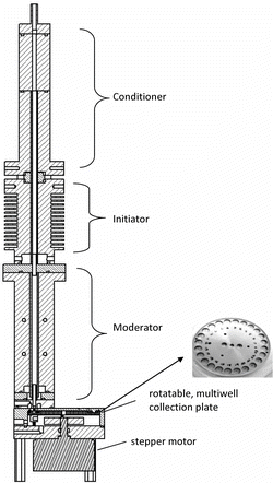
The flow exits the growth tube through a single, 1.2-mm diameter nozzle and impinges into one of the wells of the multiwell collection plate. The multiwell plate contains 24 evenly spaced wells, each measuring 6 mm in diameter, 3 mm in depth, and capable of holding 100 μL of solution. A spring loaded mount pushes the well-plate up against a donut-shaped Teflon gasket mounted on the ceiling of the collection chamber that covers all but the active well. This shields the nonactive wells from the flow, and minimizes the head space for volatilization of already-deposited samples. The well-plate has a small, spring-loaded heater that touches the bottom side of the multiwell plate immediately underneath the active well. Its temperature is selected to prevent condensation, and to evaporate droplets as they collect, and its setting depends on the details of the multiwell plate material and thickness. There is also a small heater on the nozzle mount to prevent water condensation in the nozzle. A small stepper motor advances the plate to the next well at the end of each collection period.
A microprocessor controls five temperatures, the conditioner temperature, the initiator-conditioner temperature difference, the moderator, the impaction nozzle, and the multiwell plate temperatures. Under normal operation the conditioner is operated at 2°C–5°C, the initiator is set to 30°C warmer than the conditioner (i.e., 32°C–35°C), and the moderator is set to 10°C–12°C. Maintaining a constant temperature difference between the initiator and conditioner provides the same supersaturation, and hence the same particle activation and growth, regardless of slight variations in the absolute temperatures (Lewis and Hering Citation2013). The temperature controllers for the conditioner and moderator regulate the power to their respective TEDs, while the controller for the initiator cycles the initiator heat sink fans.
The microprocessor also controls the well-plate position, and logs the instrument status. The user may select the duration for each sample (in minutes or hours) and further has the option for either “synchronized” or “unsynchronized” modes. When “synchronized” the sampling schedule aligns with midnight (e.g., with hourly samples starting at the top of the hour, twice daily samples starting at noon and midnight), while “unsynchronized” sampling starts immediately upon receiving the command. The sample and parasitic water transport flows are controlled by means of small valves and an external pump. For ambient air sampling an external cyclone, with transport flow as needed, is used to provide an inlet precut, typically 2.5 μm.
Analytical Interface
Sample extraction and analysis for identification and quantification of inorganic anions was handled by a Dionex ion chromatograph (Model 2100) equipped with a KOH eluent generator (Model EGC III) and a Dionex autosampler (Model AS). This autosampler has a stationary sample tray, and a sample needle arm that moves among fixed x-y positions corresponding to expected vial locations. As our multiwell plate is round, and the needle movements are restricted to specific x-y locations, a custom adapter was built. The adapter mounts in the autosampler, in place of the normal vial tray. It has a platform that holds the collection plate and a small stepper motor that rotates the plate upon command to locate the active well at one of the x-y vial locations. The multiwell plate rotation is controlled and triggered through one of the autosampler TTL outputs.
For analysis the dry multiwell plate, as it comes from the sampler, is placed directly into the autosampler, on the multiwell plate adapter. The autosampler delivers 80 μL of eluent to the active sample well. The sample in this well is allowed to soak for 30–60 min (2–4 chromatographic analysis periods), after which 20 μL of the extract is injected onto the analytical system. During the soak period the well-plate is rotated so that previously prepared samples can be injected. The eluent contains an internal standard to correct for evaporative losses during the soaking period. The complete set of multiwell plate samples are analyzed, without user intervention, using the Chromeleon software provided by Dionex.
Automated extraction and analysis optimization was conducted using a commercially available seven anion standard solution (Dionex, part #56933) and dichloroacetic acid (DCA) as internal standard. Optimum separation of the compounds was obtained in under 15 min using an Ion Pac AS18 column with a gradient water/KOH mobile phase starting at 20 mM KOH and ending at 44 mM KOH. Every sample sequence included a 5-point calibration curve and sample blanks. Initial testing was conducted by spiking blank plates with a stock solution containing the seven anions and DCA, and letting it dry prior to extraction and analysis.
Numerical Modeling
The design of the condensational growth component was guided by numeric modeling of the concentration-dependent temperature and saturation profiles, as described by Lewis and Hering (Citation2013). This model was written in the Igor programming environment (Wavemetrics, Beaverton, OR), and solves the 2-D axial symmetric diffusion equations for heat and mass transfer assuming a fully developed laminar flow profile. Condensational growth of the activated particles is calculated along each step of the trajectory by solving the coupled, quasistatic mass and energy balance relations. Concentration effects are modeled iteratively through recalculation of the flow temperature and water vapor content at each time step to account for the loss of water vapor and the release of heat from condensation. These growth calculations assume wettable, insoluble particles, i.e., the Kelvin effect is included but solute effects are ignored, as are the kinetics of particle activation. The model was verified in the low concentration limit by comparison to Stolzenburg and McMurry (Citation1991).
Collection Efficiency Measurements
Particle collection efficiency was inferred from measurement of particle penetration through the sampler. For submicrometer particle sizes, the aerosol was generated through atomization, mixing 10:1 with dry air, charge neutralized using the TSI soft X-Ray source and size selected using either a high-flow differential mobility analyzer (HF-DMA, Stolzenburg et al., Citation1998), or the TSI Model 3085 nano-DMA. The DMAs were operated with single-pass, 15 L/min sheath flow comprised of filtered laboratory air (with relative humidity of 30%–40%). Aerosol input and output flows were both 1.5 L/min and monitored via capillary flow meter. Dilution air was added at the DMA output and passed through a mixing tube prior to delivery to the instruments. Particle concentrations at the inlet to the sequential spot sampler, and in the exiting flow were monitored using a pair of water-based condensation particle counters (TSI Model 3783 and 3787). These tests were done as a function of particle size, and at selected sizes, as a function of particle number concentration. To span larger particle sizes, in the range of 0.6 μm–2.5 μm, tests were conducted with Arizona Test Dust generated via a fluidized bed (TSI Model 3400A) equipped with a Kr-85 charge neutralizer, with comparison between upstream and downstream size distributions measured with an aerodynamic particle sizer (APS, TSI Model 3321).
Inorganic Ion Recovery and Volatilization Testing
Inorganic ion recovery was measured using a laboratory aerosol generated by atomization of a mix of ammonium sulfate and ammonium nitrate prepared in double distilled water, and size selected with the HF-DMA as described above. Tests were done at a particle mobility diameter of 100 nm. The delivered number concentration was monitored with a WCPC (TSI Model 3783), and the proportion of multiply charged particles was measured using a high sensitivity optical particle spectrometer (Droplet Measurements, UHAS), which has a stated detection limit near 60 nm. Downstream concentrations were monitored with a second WCPC (TSI 3787) that pulled the flow of the sequential spot sampler. The mass of sulfate and nitrate collected was measured by ion chromatography, as described above. For selected tests, sampling was done in parallel with prewashed 25-mm diameter nylasorb filters operated at 3.0 L/min. Filters were extracted in 1 mL of 18 Mohm water using either 1-h soaking followed by 40-min sonication, or by 60 min of sonication, with the sonication bath changed every 15 min to prevent sample heating, and analyzed by ion chromatography.
Ambient Measurements
Ambient particles below 2.5-μm aerodynamic diameter (PM2.5) were collected by sampling downstream of a cyclone precut over a six-consecutive day period in Berkeley, CA. Collection was done without a vapor denuder upstream. The first multiwell plate was run for three days, with 3-h sample collection. Sampling was then switched to 1-h time resolution with daily exchanges of the plate. Upon removal from the sampler the multiwell plate was placed in a plastic Petri dish, sealed with Teflon tape, and stored in a refrigerator. For analysis, multiwell plate was placed on the ion chromatographic autosampler, which handled the extractions and injections automatically, as described above.
RESULTS
Modeled Saturation Ratio and Temperature Profiles
shows model calculations for the sequential spot sampler when operated at the wall temperatures of 5°C, 35°C, and 11°C for the conditioner, initiator, and moderator stages, respectively, with an input flow at 22°C and 50% RH. The assumed wall temperature profile is shown in top panel of , where the wall temperature at the transition between each of the sections of the growth tube is modeled as a linear ramp. The airflow temperature, saturation ratio, and calculated droplet diameter are shown in the subsequent panels. Results are presented for streamlines at three different radial positions. For each streamline trajectory the low particle concentration limit is indicated by solid lines, where condensational heating and vapor depletion are neglected, while calculations for a concentration of activated particles of 105/cm3, are given by the dashed lines.
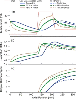
Neglecting diffusion, particles follow a single streamline as they travel down the growth tube. Those along the centerline experience a peak supersaturation between 1.3 and 1.4, depending on the input particle concentration. The Kelvin equivalent diameters are 6.6 nm–8.3 nm, indicating that a wettable, insoluble particle of this size will activate and grow. In the center the temperature of the flow does not exceed 23°C, even at high particle concentrations. Although the flow remains supersaturated at the exit, the temperature is below the inlet temperature, such that the water content of the flow at the exit is below the saturation value at the assumed ambient temperature of 22°C.
At larger radial positions, the streamlines experience somewhat higher temperatures, and lower peak supersaturations. For parabolic flow profiles, approximately one-half of the flow will lie inside the trajectory at a radial position of 0.55 Ro, where Ro = tube radius. The peak temperature along this streamline is 26°C, and is the highest temperature seen by the central core comprising one-half of the flow. For the streamlines at 0.75R0, which encompasses approximately 80% of the flow, the temperature reaches 30°C. These profiles nearer to the wall are not as greatly affected by the presence of other particles as is the centerline streamline, and modeled Kelvin equivalent diameter values are within the range of 8.2 ± 0.4 nm. The water content of the flow at the exit is yet lower than that from the centerline, so that once the flow is warmed to ambient conditions it will be subsaturated.
Droplet growth, modeled for an initial particle size of 40 nm, is shown in the bottom panel of . At this size particle activation and initial growth occurs in the initiator, and continues throughout the moderator section. Smaller particles, and those closest to the centerline, activate further downstream. The droplet size is larger near the walls of the tube because the flow is slower, and hence there is more time for growth. The number concentration of activated particles limits the extent of particle growth, primarily due to condensational heating that reduces the saturation ratio. The sequential spot sampler uses a narrow diameter growth tube to minimize the concentration effects, as described by Lewis and Hering (Citation2013). Modeled droplet sizes at the exit are 3–4 μm at low particle concentrations, and 2–3 μm at 105 particles/cm3.
Particle Collection Efficiency
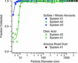
The size dependent particle collection efficiency, as inferred from particle penetration measurements, is shown in . Data are given for three systems, and for both hygroscopic and hydrophobic aerosols. At 12 nm, both aerosol types are collected with efficiency of 99%. At smaller sizes, the collection efficiency is higher for the sulfate/nitrate mix than for oleic acid, which is a hydrophobic oil. At 8 nm the collection efficiency is 98% for the sulfate/nitrate solution and 40% for oleic acid. Measurements for particle sizes up to 2.5 μm, made with size-selected sulfate/nitrate and with Arizona Test Dust, indicate high collection efficiencies over the entire 0.01–2.5-μm size range. Efficient collection at small particle sizes is especially important for assaying species such as polycyclic aromatic hydrocarbons that may be found predominantly in the ultrafine size fraction.
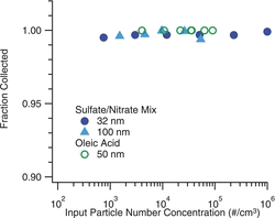
shows the dependence of the collection efficiency on the number concentration of particles sampled. These tests were conducted to ensure that the reduction in peak supersaturation, which occurs at high particle concentrations, does not impair the collection. Tests were done for both oleic acid and sulfate-nitrate aerosols using monodisperse particles with diameters ranging from 32 to 100 nm, and concentrations extending up to 105 cm−3 for oleic acid, and 106 cm−3 for the ion mix. These data show no degradation in the collection efficiency with increasing concentrations for either particle type.
Recovery of Laboratory Generated Aerosols
The deposition and recovery from the sequential spot sampler wells was evaluated using particles generated by atomization of a solution of ammonium sulfate and ammonium nitrate, and size-selected with the HF-DMA. Samples of varying duration, from 1 to 26 h, were collected into the multiwell plates, and these were analyzed by ion chromatography, as described above. The collected mass from the chemical analysis is compared to the volume of aerosol collected indicated by the physical measurements of mobility diameters and number concentrations. For these comparisons, the “mobility-volume” is calculated from the mobility equivalent diameters DBi given by the operational parameters of the HF-DMA, and the relative concentrations n1, n2,… n5, of particles at each charge state i, as measured in parallel with the optical spectrometer (i.e., π/6 (n1DB13 + n2DB23 +….+ n5DB53)). Particles carrying up to five charges were included. The primary mobility size, at i = 1, was 100 nm.
shows these results. The sequential spot sampler dry mass is calculated assuming the sulfate and nitrate are present as their ammonium salts. The mobility volume is multiplied by unit density for easier comparison. The symbol shape indicates data from a single run, corresponding to samples from a single multiwell plate. During each run, the duration of the collection in each well was varied, and this is indicated by the color, or shading of the points. While there is some scatter, the data show fairly equivalent recovery over a range of collection times. A fit through the data yields a slope of 1.3 ± 0.1 g/cm3.
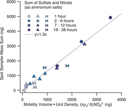
A difficulty in comparing this slope, which indicates an effective density, to the bulk material density (1.75 g/cm3 for our salt mixture) is that we do not know how much water may be associated with the test particles. The test aerosol contained both ammonium nitrate and ammonium sulfate to enable testing of the relative recovery of ammonium nitrate, a volatile constituent, to ammonium sulfate, which is stable. However, ammonium nitrate especially tends to hold onto its water. The mobility size selection was done at relative humidity values of 30% to 50%. In this RH range Tang (Citation1980) reports diameter growth factors, defined as the ratio of actual to dry particle diameter, of 1.1 ± 0.05. This corresponds to a water volume fraction of 25%, and yields an effective density of 1.3 g/cm3, similar to that which was measured. If the test particles were truly dry, the effective density would be lower than the bulk density due to the dynamic shape factor (Zelenyuk et al. Citation2006), but would still be higher than indicated by our data, with a value near 1.6 g/cm3. With these uncertainties regarding associated water, the aerosol size and concentration data are used to compare among runs, but not as an absolute calibration.
For two of the sets of experiments, collection was done in parallel with nylon filters that were also analyzed by ion chromatography. These data were well correlated, with R2 values of 0.98 and 0.90 for sulfate and nitrate, respectively, but values from the sequential spot sampler were approximately 30% higher for sulfate and 50% higher for nitrate than obtained with the filters. We could not trace the source of this discrepancy. Khlystov et al. (Citation2005) reported positive artifacts for nitrate when using condensation systems. To look for possible gas-phase artifacts in our system, additional experiments were conducted using the same test configuration, but with a sucrose aerosol mixed with filtered ambient air to which 3 μg/m3 of nitric acid was added via a perm tube. None of these experiments produced measurable quantities of sulfate or nitrate with our sampler.
Volatilization Testing
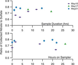
To evaluate the loss of volatile material in the sampler, we examined relative recovery of ammonium nitrate to ammonium sulfate for the laboratory aerosol tests presented above. The top panel of shows the measured ratio for three sets of experiments with sample duration of 1 to 20 h. The bottom panel shows this ratio as a function of storage time on the sampler, computed as the time from the end of the collection in a specific well until the removal of the multiwell plate from the sampler. The aerosol generation rates were fairly constant over each run, with concentrations of the order of 1–2 μg/m3 each for sulfate and nitrate. These data show no loss of nitrate during collection, nor during storage on the sampler. In a more severe test, where particle-free air is drawn across the sample for more than 12 h after collection, losses in excess of 50% of the ammonium nitrate were observed. As suggested by Zhang and McMurry (Citation1991), with impaction collection, the covering of the particle deposit by the newly collected particles reduces the volatilization losses.
Linearity and Precision
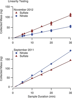
To evaluate the extraction of the samples from the wells, the linearity of response was tested by generating a steady concentration of aerosol, and sampling for varying durations, ranging from 5 to 30 min. Two sets of these tests were conducted, first when the samplers were new, and then approximately one year later, as shown in . During the intervening year the sampler had been used for four months of continuous sampling, and was still operating with its original wick. Linear regressions yield correlations with R2 > 0.99, indicating a linear response. The intercept values tended to be slightly negative, but always fell within two standard deviations of 0. The relative slopes for the sulfate and nitrate differ between the two sets of tests because of proportion of sulfate to nitrate in the atomizing solutions were not the same.
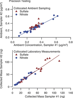
Precision data from collocated samplers for both laboratory aerosol and ambient data are shown in . Ambient data are for sequential, 1-h sampling over a 23-h period. For nitrate the concentrations ranged from near zero to 0.7 μg/m3, and linear regression gives R2 = 0.95 with no systematic bias between the two samplers. For sulfate the concentration range is small, with a poorer correlation attributable to one outlier point, which happens to have been the first sample of the series, and perhaps points to a source of contamination that could be avoided with refined protocols. The pooled standard deviation for these measurements (including the outlier) is 0.04 μg/m3 and 0.03 μg/m3 for sulfate and nitrate, respectively, or 11% of the mean. For laboratory aerosol we compare the mass collected by each of two samplers, both operated at the same flow rate with a constant aerosol source, but varying collection duration. For this dataset we compare the mass of deposited material, and find the pooled standard deviation is 4 ng and 8 ng for sulfate and nitrate. For hourly sampling (0.09 m3 of air) this corresponds to precisions of 0.04 μg/m3 and 0.09 μg/m3, similar to that measured in our ambient sampling.
Example Ambient Data
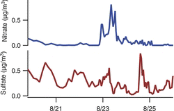
shows ambient PM2.5 sulfate and nitrate concentrations measured with the sampler, in Berkeley, CA, over a six-day period. A single mutliwell collection plate spanned the first three days of measurements, with 3-h time resolution. For the remaining three days the time resolution was increased to hourly, with the multiwell plate changed daily. The nitrate concentrations were mostly low except for one peak in the morning hours midway through the measurement period. The sulfate concentrations did not correlate with nitrate, and showed their highest concentrations at a time when nitrate concentrations were low. Chloride was also measured, but was below 0.05 μg/m3 for most of these samples. Field evaluation of the sequential spot sampler for inorganic ions, with comparison to filter samplers and to the semicontinuous measurements from a particle-in-liquid-sampler, are presented by Hecobian et al. (2012).
CONCLUSIONS AND FUTURE WORK
The spot sampler presented here uses a new, moderated approach for laminar flow condensational growth to collect fine and ultrafine particles from a 1.5 L/min flow as 1-mm diameter, dry deposits. It has a multiwell plate for collection of sequential, time-resolved samples. Chemical analyses are done offline using an ion chromatograph. With a simple adapter to an autosampler, the sample extraction, injection, and ion analysis are done in a fully automated manner, without user intervention. Laboratory measurements show that collection efficiencies are above 95% for particles larger than 8 ± 2 nm in diameter. Tests with mixed of ammonium nitrate and ammonium sulfate aerosol show that the ratio of recovered nitrate to sulfate was independent of the duration of collection, or the duration of storage on the sampler, indicating that volatilization losses were minimal. Precision for hourly sampling of sulfates and nitrates is 0.04–0.09 μg/m3.
The sequential spot sampler and its laboratory interface have been designed to provide a fairly labor-free approach to time-resolved chemical speciation of ambient particulate matter, without needing to maintain analytical equipment in the field. The automation of the laboratory analysis is facilitated by the concentrated nature of the particle collection. In turn, this concentrated particle collection is enabled through use of a new, temperature-moderated particle condensation method that activates growth in the 10-nm size range without significant warming, and without elevating water vapor content in the output flow. The collection as droplets eliminates particle bounce upon impact, while the immediate evaporation of the droplets upon collection leaves a dry deposit. With dry deposits the samples are relatively stable chemically, and are transported as easily as filter samples.
While results presented here focus on anions, the sequential spot sampler is compatible with a range of analyses. Extensions to polycylic aromatic hydrocarbons are described by Eiguren Fernandez et al. (Citation2014), and results for levoglucosan were presented by Hecobian et al. (2012). Refinements such as use of vapor denuders or incorporation of a means to protect the multiwell plates during analysis, as may be needed to facilitate measurement of ammonium ion or other species subject to gas-phase interferences, have yet to be addressed. Beyond ion and liquid chromatography, the concentrated nature of the collection provided by the sequential spot sampler is likely appropriate for a number of direct analyses such as laser induced break down spectroscopy, or energy dispersive elemental analysis. These additional applications are just beginning to be explored.
FUNDING
This research work was supported by the NIH grant RC3ES019081.
REFERENCES
- Birch, M.E., and Cary, R.A. (1996). Elemental Carbon-Based Method for Monitoring Occupational Exposures to Particulate Diesel Exhaust. Aerosol Sci. Technol., 25:221–241.
- Eiguren Fernandez, A., Lewis, G.S., Spielman, S.R., and Hering, S.V. (2014). Time-Resolved Characterization of Particle Associated Polycyclic Aromatic Hydrocarbons Using a Newly Developed Sequential Spot Sampler with Automated Extraction and Analysis. submitted.
- Hecobian, A., Eiguren Fernandez, A., Sullivan, A.P. , Lewis, G., Hering, S., Henry, C. S., and Collett, J.L. (2012). Field and Laboratory Evaluation of a Sequential Time Resolved Aerosol Composition Measurement Instrument. Presented at the Annual Meeting of the American Association for Aerosol Research, . Minneapolis, MN, USA.
- Hering, S.V., Speilman, S.R., and Lewis, G.L. (2014). Moderated, Water-Based Condensational Growth of Particles in a Laminar Flow. Aerosol Sci. Technol., 48:401–408.
- Khlystov, A., Wyers, G.P., and Slanina, J. (1995). The Steam-Jet Aerosol Collector. Atmos. Environ., 29:2229–2234.
- Khlystov, A., Zhang, Q., Jimenez, J.L., Stanier, C., Pandis, S.N., Canagaratna, M.R., Fine, P., et al. (2005). In situ Concentration of Semi-Volatile Aerosol Using Water-Condensation Technology. J. Aerosol Sci., 36:866–880.
- Lewis, G.S., and Hering, S.V. (2013). Minimizing Concentration Effects in Water-Based, Laminar-Flow Condensation Particle Counters. Aerosol Sci. Technol., 47:645–654.
- Ng, N.L., Herndon, S.C., Trimborn, A., Canagaratna, M.R., Croteau, P.L., Onasch, T.B., Sueper, D., et al. (2011). An Aerosol Chemical Speciation Monitor (ACSM) for Routine Monitoring of the Composition and Mass Concentrations of Ambient Aerosol. Aerosol Sci. Technol., 45:780–794.
- Orsini, D.A., Ma, Y.L., Sullivan, A., Sierau, B., Baumann, K., and Weber, R.J. (2003). Refinements to the Particle-Into-Liquid Sampler (PILS) for Ground and Airborne Measurements of Water Soluble Aerosol Composition. Atmos. Environ., 37:1243–1259.
- Stolzenburg, M., Kreisberg, N., and Hering, S. (1998). Atmospheric Size Distributions Measured by Differential Mobility Optical Particle Size Spectrometry. Aerosol Sci. Technol., 29:402–418.
- Stolzenburg, M.R., and McMurry, P.H. (1991). An Ultrafine Aerosol Condensation Nucleus Counter. Aerosol Sci. Technol., 14:48–65.
- Tang, I.N. (1980). Deliquescence Properties and Particle Size Change of Hygroscopic Aerosols, in Generation of Aerosols and Facilities for Exposure Experiments, K. Willeke, ed., Ann Arobr Science, Ann Arbor, MI , pp. 153–168.
- Turpin, B.J., Cary, R.A., and Huntzicker, J.J. (1990). An in-situ, Time-Resolved Analyzer for Aerosol Organic and Elemental Carbon. Aerosol Sci. Technol., 12:161–171.
- Weber, R.J., Orsini, D., Daun, Y., Lee, Y.N., Klotz, P.J., and Brechtel, F. (2001). A Particle-Into-Liquid Collector for Rapid Measurement of Aerosol Bulk Chemical Composition. Aerosol Sci. Technol., 35:718–727.
- Zelenyuk, A., Cai, Y., and Imre, D. (2006). From Agglomerates of Spheres to Irregularly Shaped Particles: Determination of Dynamic Shape Factors from Measurements of Mobility and Vacuum Aerodynamic Diameters. Aerosol Sci. Technol., 40:197–217.
- Zhang, X.Q., and McMurry, P.H. (1991). Theoretical Analysis of Evaporative Losses of Adsorbed or Absorbed Species During Atmospheric Aerosol Sampling. Environ. Sci. Technol., 25:456–459.

