Abstract
A simple sampling method to collect aerosol particles for transmission electron microscope (TEM) analysis was developed by R’mili and others in 2013. The method involves passing air through a holey carbon film-coated copper mesh TEM grid (holey carbon grid) and sampling particles by filtration. In this study, we proposed a modified calculation method to represent the collection efficiencies of holey carbon grids, taking into consideration the porosity of the copper mesh. We then evaluated the particle collection efficiencies of holey carbon grids both theoretically and experimentally. We tested the collection efficiency of two types of holey carbon grids, with nominal pore sizes of 1.2 and 0.6 μm, using particles of monodispersed polystyrene latex (PSL) and potassium chloride. The overall collection efficiency of each grid (Egrid) was determined by the downstream/upstream concentration ratio measured by condensation particle counters (CPCs). In addition, for PSL particles, the collection efficiency of the holey carbon film (Efilm) was determined by the ratio of the number of particles on the film (counted on a scanning electron microscope) to the number of inflow particles (counted by a CPC). We compared model calculations against the experimental results obtained in this study and those reported by R’mili and others in 2013. These data showed that the calculated Egrid values were in reasonably good agreement with the experimental Egrid values. However, although the model calculation indicated that Efilm ≈ Egrid, there was an inconsistency between the experimental Efilm and Egrid, which requires further investigation in order to determine its cause.
Copyright 2014 American Association for Aerosol Research
1. INTRODUCTION
A transmission electron microscope (TEM), often used in conjunction with an energy-dispersive X-ray analytical system, is an effective tool for the analysis of aerosol particles. It can accurately determine particle size, morphology, and composition. For example, in studies on the risks associated with nanomaterials, TEM observation is a reliable way to verify the presence and form of aerosolized nanomaterials, and to differentiate between nanomaterials and background particles (Methner et al. Citation2010).
The success of TEM observation is strongly dependent on the particle sampling method used. It is necessary to collect particles onto a grid specifically used for TEM observation (i.e., a TEM grid), which typically has a diameter of approximately 3 mm. Various methods have been proposed for direct particle collection, such as electrostatic precipitation (Cheng et al. Citation1981; Dixkens and Fissan Citation1999; Fierz et al. Citation2007; Miller et al. Citation2010), thermophoretic precipitation (Bang and Murr Citation2002; Lyyränen et al. Citation2009; R’mili et al. Citation2011), inertial impaction (Birch et al. Citation2011), or Brownian motion (Tsai et al. Citation2009). Meanwhile, an indirect method commonly used to measure asbestos involves dissolution of the filter after particle collection so that the particles are transferred onto a TEM grid (National Institute for Occupational Safety and Health [NIOSH] Citation1994; International Organization for Standardization [ISO] Citation1995; Methner et al. Citation2010). However, all these methods have drawbacks in that a specific device is required, collection efficiency is low or unknown, or preparation is time-consuming.
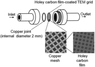
A simple sampling method for collecting aerosol particles on a TEM grid has recently been proposed and developed by Lyyränen et al. (Citation2009) and R’mili et al. (Citation2011, Citation2013). In this method, air is passed through a holey carbon film-coated copper mesh TEM grid (holey carbon grid) and particles are sampled by filtration (). This method is low-cost, compact, and portable, and sample preparation is not required. Although collection efficiency with this method depends on particle size, efficiency is nevertheless relatively high compared to other collection techniques. R’mili et al. (Citation2013) evaluated the collection efficiency of two types of holey carbon grids: the first had uniformly-sized circular pores arranged regularly, while the second had nonuniformly-sized irregular pores distributed randomly. Collection efficiency was tested using monodispersed copper (Cu) and sodium chloride (NaCl) particles with a particle size of 5–150 nm at a volume flow rate of 0.3 L·min−1. They reported a minimum collection efficiency of 15%–18% at a particle size of around 30 nm.
Like Nuclepore filters, holey carbon grids have circular pores. Therefore, the collection efficiencies of holey carbon grids can be estimated by employing models developed for calculating the collection efficiencies of Nuclepore filters. R’mili et al. (Citation2013) used this technique to calculate the collection efficiencies of holey carbon grids, and reported a good agreement between the model calculation and the experimental results. However, their calculation method has room for improvement. First, they did not consider the porosity of the copper mesh, which was approximately 50%. As a result, the actual velocity of the flow approaching and passing through the pores of the carbon film was approximately two times higher than the value they assumed; this is problematic because flow velocity affects the calculated collection efficiencies by both impaction and diffusion. Second, although the effect of impaction largely depends on particle density (Pich Citation1964), the difference in densities between the Cu and NaCl particles was not considered in the model calculation. Third, Equation (15) in R’mili et al. (Citation2013), which was used to calculate the collection efficiency due to Brownian diffusion, was invalid for this situation as it only expressed single-fiber efficiency by diffusion. An additional factor was needed in order to apply this single-fiber theory and obtain the efficiency of the entire film (Yamamoto et al. Citation2005). Furthermore, the equation to obtain Kuwabara's hydrodynamic factor (Ku), used in Equation (15) of R’mili et al. (Citation2013), differs from the original equation (Kirsch and Fuchs Citation1968; Hinds Citation1999).
In this article, we propose a modified calculation method to represent the collection efficiencies of holey carbon grids, taking into consideration the porosity of the copper mesh. We then compare the model calculation with experimental results reported by R’mili et al. (Citation2013), and with those obtained in this study. We experimentally tested the collection efficiency of two types of holey carbon grids, with nominal pore sizes of 1.2 and 0.6 μm, using monodispersed polystyrene latex (PSL) spherical particles and potassium chloride (KCl) particles. The overall collection efficiency of each grid was determined by the downstream/upstream concentration ratio measured by condensation particle counters (CPCs). In addition, for PSL particles, the collection efficiency of the holey carbon film on each grid was determined by the ratio of the number of particles on the grid (visually counted on a SEM) to the number of inflow particles (counted by a CPC).
2 MATERIALS AND METHOD
2.1 Holey Carbon Grids and Sampling System
In this study, we used two types of holey carbon grids. Both were 200-mesh copper grids coated with a carbon support film, and both had circular pores. The first had a nominal pore size of 1.2 μm and nominal pore spacing of 1.3 μm (Quantifoil R1.2/1.3 on 200 mesh Cu, Agar Scientific, Stansted, UK; hereafter Grid-1); the second had a nominal pore size of 0.6 μm and nominal pore spacing of 1 μm (Quantifoil R0.6/1 on 200 mesh Cu, Agar Scientific; hereafter Grid-2). In contrast, R’mili et al. (Citation2013) used 400-mesh copper grids coated with a carbon support film; circular pores in these grids had a nominal pore size of 1.2 μm and nominal pore spacing of 1.3 μm (Quantifoil R1.2/1.3 on 400 mesh Cu, Agar Scientific; hereafter Grid-3). The structural characteristics of all three grids are summarized in .
TABLE 1 Structural characteristics of the holey carbon film-coated TEM grids
A field-emission SEM (Quanta 250 FEG, FEI Company, USA) was used to measure structural characteristics for both Grid-1 and Grid-2, which were compared to nominal values provided by the manufacturer (). The measured pore diameters were somewhat different from the nominal values. Although there was relatively little variation in the diameter of pores within a grid, there was large variation in the diameter of pores among grids (grid-to-grid variation), especially with Grid-2. In contrast, the measured pore pitch (= pore diameter + pore spacing) was fairly stable and consistent with the nominal pore pitch. The measured width and pitch of the square holes in the copper mesh were also fairly stable. The width of the hole at the front of the mesh, to which the holey carbon film was attached, was somewhat larger than at the back ().
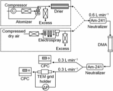
is a diagram of an aerosol particle collection system with a holey carbon grid; it is the same as the one used by R’mili et al. (Citation2013). A holey carbon grid with a copper joint (hole grid Cu 2000 μm, Agar Scientific; external diameter = 3.05 mm, internal diameter = 2 mm) was placed in a TEM grid holder (Mini Particle Sampler, MPS, Ecomesure, Janvry, France) developed by the Institut National de l’Environnement Industriel et des Risques, (INERIS, France) (R’mili et al. Citation2013). The volume flow rate was fixed at 0.3 L·min−1. This value was recommended by Lyyränen et al. (Citation2009) in order to avoid deterioration of the carbon film on the TEM grid, and was used by R’mili et al. (Citation2013). Pressure-drops occurring through the holey carbon grids at this volume flow rate were 1.1 ± 0.14 kPa for Grid-1 and 1.7 ± 0.51 kPa for Grid-2 (values are given as mean ± standard deviation; n = 29 and 28, respectively).
2.2 Experimental Setup for Evaluating the Collection Efficiency
The experimental setup used for evaluating the collection efficiency of the holey carbon grids is shown in . Conductive silicone tubing and stainless steel connectors were used to transmit the particles. An atomizer (model ATM-226, Topas, Dresden, Germany), followed by a silica gel drier, were used to generate PSL spherical particles 100 and 300 nm in size, and KCl particles 30, 50, and 100 nm in size. In addition, an electrospray (model 3480, TSI, Shoreview, MN, USA) was used to generate PSL spherical particles of 30 and 50 nm, and KCl particles of 5, 10, and 15 nm. The KCl concentrations in solutions for the atomizer and electrospray were 0.02–0.07 and 0.25 g·L−1, respectively. The aerosolized particles were neutralized by a radioactive source (americium [Am]-241) to establish an equilibrium charge distribution. These were then classified by a differential mobility analyzer (DMA; model 3081 or 3085, TSI) with a platform (model 3080, TSI) to obtain monodispersed particles, and to remove the residuals of ultrapure water used for the PSL and KCl solutions. The charges on the monodispersed particles passing through the DMA were subsequently removed by another Am-241 source. The number concentrations of particles upstream and downstream of the TEM grid holder were measured by two separate CPCs (models 3776 and 3775, TSI, respectively). The lines from the bifurcation to the upper CPC and the TEM grid holder were the same lengths in order to avoid differing particle losses in the two sets of tubing. The number concentrations of particles upstream of the TEM grid holder were recorded as being on the order of magnitude of 102–103 particles·cm−3. The sampling time ranged between a few minutes and a few hours, depending on the concentration and particle size. Tests for each size and composition of particles were repeated at least three times.
2.3 Determination of the Collection Efficiency
Penetration (Pt) is expressed by:
[1] where Cup and Cdown are the number concentrations of particles upstream and downstream of the TEM grid holder, respectively. The overall collection efficiency of the holey carbon grid (Egrid) was calculated according to the ratio of penetrations with (Pt,with) and without (Pt,without) the holey carbon grid; in the latter case, only the copper joint was used (). This calculation took into account the counters’ own intrinsic differences and the loss of particles through the holder and tubing:
[2]
For PSL particles, the collection efficiency of the holey carbon film on the grid (Efilm) was also determined by the ratio of particles on the holey carbon film (visually counted on an SEM) to inflow particles (counted by a CPC):
[3] where Ndep represents the total number of particles deposited on the holey carbon film, and Nin is the total number of particles entering the grid. Ndep and Nin were calculated as:
[4]
[5] where Afilm is the effective filtration area of the holey carbon film, NSEM is the total number of particles on the holey carbon film counted on the SEM, ASEM is the total area of the holey carbon film observed on the SEM, and V is the total sampling air volume (= volume flow rate × sample collection time). Afilm was calculated as:
[6] where dj is the internal diameter of the copper joint (2 mm) and Pmesh is the fraction of the opening area (porosity) of the copper mesh ().
More than 100 particles deposited on over 20 different regions in each grid were counted. Prior to SEM observation for 30- and 50-nm PSL particles, the TEM grids containing particle deposits were coated with platinum–palladium (approximately 2 nm in thickness) in order to make identification clearer. While we used the SEM in this analysis for cost-saving reasons, some samples were also examined using a TEM (JEM-1010, JEOL, Tokyo, Japan).
3 THEORY
3.1 Models
Like Nuclepore filters, porous TEM grids have circular pores. Therefore, the collection efficiencies of holey carbon grids can be estimated by employing models developed for calculating the collection efficiencies of Nuclepore filters (Pich Citation1964; Spurny et al. Citation1969; Manton Citation1978, Citation1979). Particle collection by a Nuclepore filter is generally expressed by separate filtration mechanisms: inertial impaction on the filter surface, interception at the pore opening, and Brownian diffusion to the pore wall and front surface of the filter (Cyrs et al. Citation2010; Chen et al. Citation2013).
Collection efficiency due to impaction (EI) is calculated as (Pich Citation1964; Spurny et al. Citation1969):
[7]
[8]
[9]
[10] where Stk is the Stokes number defined in terms of r0, P is the filter porosity, m is the mass of a single aerosol particle, U0 is the face velocity, Cc is the Cunningham slip correction factor (Kim et al. Citation2005), η is the dynamic viscosity of the flow (≈1.8 × 10⁻⁵ Pa·s for air), r0 is the pore radius, ρp is the particle density, and rp is the particle radius. Although the original papers (Pich Citation1964; Spurny et al. Citation1969) did not consider Cc in the Stokes number, Equation (10) includes it (Cyrs et al. 2010; Chen et al. Citation2013).
Collection efficiency due to interception (ER) is calculated as (Marre and Palmeri Citation2001):
[11]
[12]
[13] where Nr is the particle radius normalized for the pore radius (= rp /r0), Ng is the slip parameter (= lg /r0), lg is the slip length (=1.126λ; Marre et al. Citation2004), and λ is the mean free path of gas molecules (≈0.065 μm for air). When Nr > 1, the efficiency is equal to 1 and the formula is invalid. This model is based on the assumption of Poiseuille flow with flow slip.
Manton (Citation1978) pointed out a problem in considering impaction and interception separately. The former process is calculated without accounting for the finite size of a particle, while the latter ignores the inertia of a particle relative to the flow. Manton (Citation1978) therefore calculated the collection efficiency due to the combined mechanisms of impaction and interception on the filter (EIR) from the computed trajectories of particles, and proposed an approximate expression for EIR:
[14]
[15]
[16]
[17]
[18] where a and b are functions of an inertia parameter I: a1 = 0.688500 − 1.473959P + 0.286458P2, a2 = 7.754343 − 46.535261P + 72.737760P2, a3 = 1.296234 − 4.525388P + 6.554401P2, b1 = 2.720000 − 33.125000P + 65.625000P2, b2 = 16.117649 − 36.715870P + 27.829932P2, and b3 = − 10.611610 + 28.831488P − 31.098401P2. Stk’ is the Stokes number defined in terms of the radius (D0) of the cylindrical flow approaching a pore (where D0 = r0/
, as D0 is defined based on the porosity: P = πr02/πD02 = the sectional area of a pore/the sectional area of the flow approaching a pore). a1, a2, a3, b1, b2, and b3 were derived from the calculation for the cases of I = 0.25, 2, and 100, and P = 0.04, 0.16, and 0.36. EquationEquation (14)
[14] is valid within the limits: I ≤ 100 and 0.04 ≤ P ≤ 0.36. Although Manton (Citation1978) did not consider Cc in the Stokes number, Equation (18) includes it. Manton (Citation1978) proposed I to specify the collection efficiency for a parameter that depends on the filter geometry, flow conditions, and particle density, but not on particle size. However, when Cc is taken into account, I is expressed as a function of Cc, which does depend on particle size.
The collection efficiency due to diffusion to the pore wall of the filter (EW) can be calculated as (Gormley and Kennedy Citation1949; Twomey Citation1962; Spurny et al. Citation1969):
[19] where ND = LDpP/r02U0, L is the filter thickness (pore length), and Dp is the particle diffusion coefficient.
The collection efficiency due to diffusion to the front surface of the filter (EDS) can be calculated as (Manton Citation1979):
[20] where α1 = 4.57 − 6.46P + 4.58P2, α2 = 4.5, and
is the normalized particle diffusion coefficient (= Dp/D0U0). The function α1 (P) was determined by a least-squares fitting of data from a series of solutions for P = 0.05, 0.32, and 0.64; therefore, EquationEquation (20)
[20] is valid for filter porosities (P) in the range 0.05–0.64.
The overall collection efficiency (EO) can be expressed as:
[21]
These models are valid when the flow approaching a pore is laminar, which occurs at a low Reynolds number (Re). The Re of a flow approaching a pore can be calculated as (Manton Citation1978):
[22] where ν is the kinematic viscosity of the flow (≈1.5 × 10⁻⁵ m2·s−1 for air).
3.2 Application of the Models to the Collection Efficiency of the Holey Carbon Grid
For each holey carbon grid, we considered the collection efficiencies of the holey carbon film (Efilm) and the copper mesh (Emesh) separately. We calculated the collection efficiencies of the three types of holey carbon grids listed in ; Grid-1 and Grid-2 were used for the tests conducted in this study, while Grid-3 was used for the tests conducted in R’mili et al. (Citation2013).
The individual collection efficiencies, EI, ER, EIR, EW, and EDS, of the holey carbon film were calculated by Equations (7), (11), (14), (19), and (20), respectively. In these calculations, the pore radius (dfilm/2), porosity (Pfilm), and thickness (Lfilm) of the holey carbon film, and the velocity of the flow approaching a pore in the holey carbon film (Ufilm) were used instead of r0, P, L, and U0, respectively. The values of dfilm, Pfilm, and Lfilm are summarized in . Ufilm can be obtained by:
[23] where Q is the volume flow rate (0.3 L·min−1).
The total collection efficiency of the holey carbon film (Efilm) was calculated as:
[24]
TABLE 2 Conditions of the flow through the holey carbon film-coated TEM gridsa
We used EIR, instead of EI and ER, since EIR gave better estimates (see results and discussion).
Although the copper mesh has square holes, its approximate individual collection efficiencies, EI, ER, EW, and EDS, were calculated from Equations Equation(7)[7] , Equation(11)
[11] , Equation(19)
[19] , and Equation(20)
[20] , respectively. EIR could not be determined because the I of the flow approaching a hole in the copper mesh substantially exceeded the limits of validity for EquationEquation (14)
[14] ; this is discussed further below. In these calculations, the sectional area-equivalent circular-based hole radius (rmesh), porosity (Pmesh), and thickness (Lmesh) of the copper mesh, and the velocity of the flow approaching a hole in the copper mesh (Umesh), were used instead of r0, P, L, and U0, respectively. The values of Pmesh and Lmesh are summarized in . The sectional area-equivalent circular-based hole radius (rmesh) was calculated as:
[25] where wmesh is the width of the square hole in the copper mesh (). Umesh can be obtained by:
[26]
The total collection efficiency of the copper mesh (Emesh) was calculated as:
[27]
The overall collection efficiency (the combined efficiency of Efilm and Emesh) of the holey carbon grid (Egrid) was calculated as:
[28]
summarizes the velocities, Reynolds numbers, and inertia parameters (for the case of Cc = 1) of flows that approach a pore in the holey carbon film and a hole in the copper mesh.
Ufilm and Umesh are 2.5–3.2 and 1.6 m·s−1, respectively; these are relatively higher than those generally set for Nuclepore filters (e.g., 0.02–0.18 m·s−1; Cyrs et al. Citation2010; Chen et al. Citation2013). The flow approaching a pore in the holey carbon film has Re < 1, whereas the flow approaching a hole in the copper mesh has Re < 10, indicating that the flow is laminar in both cases. These data show that the above models would therefore be valid.
For the case of Cc = 1, a range of 7–15 was obtained for I of the flow approaching a pore in the holey carbon film, which is within the limits of validity for EquationEquation (14)[14] (i.e., I < 100). However, as particle size decreases, Cc increases and, consequently, I increases. For example, in the case of Grid-1, the I of particles with sizes below 40 nm and ρp = 1 g·cm−3 exceeded the limits of validity for EquationEquation (14)
[14] . Although some errors may arise, EquationEquation (14)
[14] was still used to calculate EIR for the holey carbon film, even when I > 100.
In contrast, the I of the flow approaching a hole in the copper mesh substantially exceeded the limits of validity for EquationEquation (14)[14] ; hence, EI and ER, instead of EIR, were used to calculate the collection efficiency of the copper mesh.
4 RESULTS AND DISCUSSION
Experimental measurements for overall collection efficiencies (Egrid) for KCl and PSL particles, and collection efficiencies of the holey carbon film (Efilm) for PSL particles are summarized in .
TABLE 3 Results of measured particle collection efficiencya
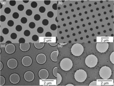
Representative SEM and TEM images of particles collected on the holey carbon grids are presented in . The PSL particles were almost spherical, whereas the KCl particles were close to cubic, but could be approximated as spheres. Although KCl particles were classified by a DMA to obtain monodispersed particles, KCl particles larger than the selected size were also found, as shown in d. This was likely due to the effects of the multiple charges.
4.1 Comparison of Filtration Mechanisms
presents the theoretical collection efficiencies for particles with ρp = 1 g·cm−3 due to individual filtration mechanisms for Grid-1. The collection efficiencies EI, ER, EIR, EW, and EDS are based on the individual filtration mechanisms of the holey carbon film, whereas Emesh represents the total collection efficiency of the copper mesh. The overall collection efficiencies (Egrid) of PSL particles (ρp ≈ 1 g·cm−3) found in the experiment are also presented in for comparison.
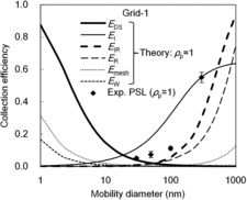
This simulation shows that diffusion to the front surface (EDS) is the prevailing mechanism for the collection of smaller particles, whereas the contribution of diffusion to the pore wall (EW) is negligible. For the collection of larger particles, impaction (EI) and interception (ER) are the prevailing mechanisms. Although the combined mechanisms of impaction and interception on the filter (EIR) obtained from Manton's model had a lesser effect than the combination of separately obtained impaction (EI) and interception (ER), EIR was in better agreement with the experimental data.
The collection efficiency of the copper mesh (Emesh) was smaller than that of the holey carbon film (the combination of EIR, EW, and EDS). This was reasonable, because the pore diameter of the holy carbon film (<2 μm) is smaller than the hole width of the copper mesh (∼100 μm) by approximately two orders of magnitude.
Similar findings were also obtained from the model calculations for Grid-2 and Grid-3 (data not shown).
4.2 Comparison Between Experimental and Theoretical Collection Efficiencies
The experimental and theoretical overall collection efficiencies (Egrid) for Grid-1, Grid-2, and Grid-3 are presented in , , and , respectively. The experimental data in are those reported by R’mili et al. (Citation2013). Because the collection efficiency due to impaction depends on ρp, and show the theoretical collection efficiencies of particles with ρp = 1 g·cm−3 (PSL) and 2 g·cm−3 (KCl). Similarly, shows the theoretical collection efficiency of particles with ρp = 1.8 g·cm−3, which is the true density of NaCl particles. Although the experimental data reported by R’mili et al. (Citation2013) include the collection efficiency of Cu particles (), the theoretical collection efficiency of particles with a density corresponding to that of Cu particles could not be calculated. This was due to two factors: (1) the density of the generated Cu particles was unknown, as the effective density of Cu particles produced by a spark-type generator would be lower than the true density of Cu (≈9 g·cm−3) (Hering and Stolzenburg Citation1995; Evans et al. Citation2003); and (2) I for high-density particles like this substantially exceeded the limits of validity for EquationEquation (14)[14] .
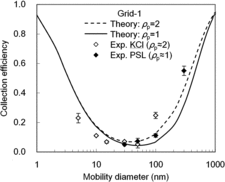
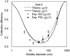
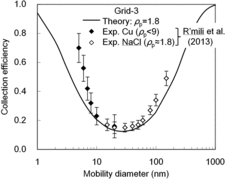
Regardless of the grid type and given conditions, the theoretical overall collection efficiencies were in reasonably good agreement with the experimental overall collection efficiencies. A slight gap between the theoretical and experimental efficiencies for KCl particles in and would be partly explained by the contributions of particles larger than the selected size. The theoretical minimum collection efficiency diameter was between 25 and 40 nm, which corresponds to the transition region between the two prevailing mechanisms, EDS and EIR ().
4.3 Differences in Efficiency Among Types of Holey Carbon Grid
The minimum overall collection efficiencies obtained experimentally in the given conditions were approximately 5%, 8%, and 15% for Grid-1, Grid-2, and Grid-3, respectively. Notably, Grid-1 and Grid-2 had a different pore size for the holey carbon film, and, as expected, a smaller pore had a higher efficiency in this case. However, the highest collection efficiency was observed for Grid-3, despite its pore size being larger than that of Grid-2. One key difference between Grid-3 and the others was the mesh size. The 400 copper mesh of Grid-3 had a lower porosity (), which resulted in a higher face velocity of the flow approaching the pores of the holey carbon film when the volume flow rate (Q) was uniform. Although a higher face velocity can decrease the deposition by diffusion, it increases the deposition by impaction, and thus increases the minimum overall collection efficiencies in the given conditions. If Q is adequately adjusted to obtain the same face velocity, the difference in efficiency between 200- and 400-mesh grids would be eliminated. However, as R’mili et al. (Citation2013) reported, 400-mesh grids (e.g., Grid-3) may be better since their small mesh holes can minimize the risk of damage to the holey carbon film under the pressure induced by flow during sampling.
As reported in Section 2.1, there was a discrepancy between actual and nominal pore sizes for Grid-1 and Grid-2. In addition, there was a large grid-to-grid variation in pore sizes, especially for Quantifoil R0.6/1 (Grid-2); consequently, the results for Grid-2 varied widely (). As Chen et al. (Citation2013) suggested for Nuclepore filters, performance of pressure-drop checks by sampling clean air before conducting the sampling is recommended in order to check the uniformity of pore sizes. In addition, performing occasional pressure-drop checks during sample collection may alert the user of damage to a holey carbon film (when the pressure decreases) or of clogging (when the pressure increases).
4.4 Collection Efficiency Obtained from Counting Particles on an Electron Microscope
The theoretical model calculation indicated that only a small number of particles were collected on the copper mesh; in fact, very few PSL particles were observed during SEM analysis on the copper mesh of the grid in any of the cases during the experiments. This finding indicates that the collection efficiency of the holey carbon film (Efilm) will be nearly equal to the overall collection efficiency (Egrid). As expected, the experimentally measured Efilm for 100- and 300-nm PSL particles were comparable to the experimentally measured Egrid (). On the other hand, the experimentally measured Efilm values for 30- and 50-nm PSL particles were approximately 30%–50% lower than the experimentally measured Egrid values (). This inconsistency may have been caused by errors in the determination of Efilm, since the experimentally measured Efilm values were determined in a complex manner. Underestimation of Efilm values may have resulted from particle loss during the SEM observation preparation process or during the SEM observation. Further studies are needed to reveal the cause of this inconsistency, which could represent a problem when particle number concentration in the air is estimated from the number of particles observed on the holey carbon film using an electron microscope.
5 CONCLUSIONS
This study evaluated the particle collection efficiencies of holey carbon film-coated copper mesh TEM grids both theoretically and experimentally; this approach can be used as a simple sampling method to collect aerosol particles for TEM analysis. We proposed a modified calculation method to represent the collection efficiencies of holey carbon grids that included consideration of the porosity of the copper mesh. Regardless of the grid type and given conditions, the calculated overall collection efficiencies were in reasonably good agreement with the experimental overall collection efficiencies. Although the theoretical calculations indicated that the collection efficiency of the holey carbon film (Efilm) would be nearly equal to the overall collection efficiency (Egrid), there was an inconsistency between the experimentally determined Efilm and Egrid. Further investigation is needed in order to reveal the cause of this inconsistency, and to establish a method for estimating the particle concentration in the air from the number of particles observed on the holey carbon film using an electron microscope.
FUNDING
The authors would like to thank the New Energy and Industrial Technology Development Organization of Japan (NEDO) for funding the study under a grant for “Innovative carbon nanotubes composite materials project toward achieving a low-carbon society” (No. P10024).
REFERENCES
- Bang, J.J., and Murr, L.E. (2002). Collecting and Characterizing Atmospheric Nanoparticles. JOM, 54:28–30.
- Birch, M.E., Ku, B.K., Evans, D.E., and Ruda-Eberenz, T.A. (2011). Exposure and Emissions Monitoring During Carbon Nanofiber Production-Part I: Elemental Carbon and Iron-Soot Aerosols.Ann. Occup. Hyg., 55:1016–1136.
- Chen, S.-C., Wang, J., Fissan, H., and Pui, D.Y. H. (2013). Use of Nuclepore Filters for Ambient and Workplace Nanoparticle Exposure Assessment–Spherical Particles. Atmos. Environ., 77:385–393.
- Cheng, Y.-S., Yeh, H.-C., and Kanapilly, G.M. (1981). Collection Efficiencies of a Point-to-Plane Electrostatic Precipitator. Am. Ind. Hyg. Assoc. J., 42:605–610.
- Cyrs, W.D., Boysen, D.A., Casuccio, G., Lersch, T., and Peters, T.M. (2010). Nanoparticle Collection Efficiency of Capillary Pore Membrane Filters. J. Aerosol Sci., 41:655–664.
- Dixkens, J., and Fissan, H. (1999). Development of an Electrostatic Precipitator for Off-Line Particle Analysis. Aerosol Sci. Technol., 30:438–453.
- Evans, D.E., Harrison, R.M., and Ayres, J.G. (2003). The Generation and Characterization of Metallic and Mixed Element Aerosols for Human Challenge Studies. Aerosol Sci. Technol., 37:975–987.
- Fierz, M., Kaegi, R., and Burtscher, H. (2007). Theoretical and Experimental Evaluation of a Portable Electrostatic TEM Sampler. Aerosol Sci. Technol., 41:520–528.
- Gormley, P.G., and Kennedy, M. (1949). Diffusion from a Stream Flowing Through a Cylindrical Tube. Proc. Roy. Irish Acad., 52A:163–169.
- Hering, S.V., and Stolzenburg, M.R. (1995). On-Line Determination of Particle Size and Density in the Nanometer Size Range. Aerosol Sci. Technol., 23:155–173.
- Hinds, W.C. (1999). Aerosol Technology: Properties, Behavior, and Measurement of Airborne Particles, 2nd edn. Wiley-Interscience, New York, p. 193.
- International Organization for Standardization (ISO) (1995). ISO 10312: Ambient Air—Determination of Asbestos Fibres—Direct Transfer Transmission Electron Microscopy Method, ISO, Geneve, Switzerland.
- Kim, J.H., Mulholland, G.W., Kukuck, S.R., and Pui, D.Y. H. (2005). Slip Correction Measurements of Certified PSL Nanoparticles using a Nanometer Differential Mobility Analyzer (Nano-DMA) for Knudsen Number from 0.5 to 83. J. Res. Natl. Inst. Stand. Technol., 110:31–54.
- Kirsch, A.A., and Fuchs, N.A. (1968). Studies on Fibrous Aerosol Filters–III Diffusional Deposition of Aerosols in Fibrous Filters. Ann. Occup. Hyg., 11:299–304.
- Lyyränen, J., Backman, U., Tapper, U., Auvinen, A., and Jokiniemi, J. (2009). A Size Selective Nanoparticle Collection Device Based on Diffusion and Thermophoresis. J. Phys. Conf. Ser., 170:012001, doi:10.1088/1742-6596/170/1/012011.
- Manton, M.J. (1978). The Impaction of Aerosols on a Nuclepore Filter. Atmos. Environ., 12:1669–1675.
- Manton, M.J. (1979). Brownian Diffusion of Aerosols to the Face of a Nuclepore Filter. Atmos. Environ., 13:525–531.
- Marre, S., and Palmeri, J. (2001). Theoretical Study of Aerosol Filtration by Nucleopore Filters: The Intermediate Crossover Regime of Brownian Diffusion and Direct Interception. J. Colloid Interface Sci., 237:230–238.
- Marre, S., Palmeri, J., Larbot, A., and Bertrand, M. (2004). Modeling of Submicrometer Aerosol Penetration Through Sintered Granular Membrane Filters. J. Colloid Interface Sci., 274:167–182.
- Methner, M., Hodson, L., Dames, A., and Geraci, C. (2010). Nanoparticle Emission Assessment Technique (NEAT) for the Identification and Measurement of Potential Inhalation Exposure to Engineered Nanomaterials–Part B: Results from 12 Field Studies. J. Occup. Environ. Hyg., 7:163–176.
- Miller, A., Frey, G., King, G., and Sunderman, C. (2010). A Handheld Electrostatic Precipitator for Sampling Airborne Particles and Nanoparticles. Aerosol Sci. Technol., 44:417–427.
- National Institute for Occupational Safety and Health (NIOSH) (1994). Asbes- tos by TEM, METHOD 7402. . NIOSH Manual of Analytical Methods (NMAM; 4th ed.), . NIOSH, Cincinnati, Ohio.
- Pich, J. (1964). Impaction of Aerosol Particles in the Neighbourhood of a Circular Hole. Collect. Czech. Chem. Commun., 29:2223–2227.
- R’mili, B., Dutouquet, C., Sirven, J., Aguerre-Chariol, O., and Frejafon, E. (2011). Analysis of Particle Release Using LIBS (Laser-Induced Breakdown Spectroscopy) and TEM (Transmission Electron Microscopy) Samplers When Handling CNT (Carbon Nanotube) Powders. J. Nanopart. Res., 13:563–577.
- R’mili, B., Le-Bihan, O.L. C., Dutouquet, C., Aguerre-Charriol, O., and Frejafon, E. (2013). Particle Sampling by TEM Grid Filtration. Aerosol Sci. Technol., 47:767–775.
- Spurny, K.R., Lodge, J.P., Frank, E.R., and Sheesley, D.C. (1969). Aerosol Filtration by Means of Nuclepore Filters: Structural and Filtration Properties. Environ. Sci. Technol., 3:453–464.
- Tsai, S.-J., Ada, E., Isaacs, J., and Ellenbecker, M. (2009). Airborne Nanoparticle Exposures Associated with the Manual Handling of Nanoalumina and Nanosilver in Fume Hoods. J. Nanopart. Res., 11:147–161.
- Twomey, S. (1962). Equations for the Decay of Diffusion of Particles in an Aerosol Flowing Through Circular or Rectangular Channels.Bull. Obs. Puy de Dôme, 10:173–180.
- Yamamoto, N., Kumagai, K., Fujii, M., Shendell, D.G., Endo, O., and Yanagisawa, Y. (2005). Size-Dependent Collection of Micrometer-Sized Particles using Nylon Mesh. Atmos. Environ., 39:3675–3685.

