Abstract
The AIST-inkjet aerosol generator (IAG) can generate highly monodisperse solid or liquid aerosol particles in the particle diameter range from 0.3 to 20 μm at precisely known particle generation rates. The device has been developed for evaluating the counting efficiencies of optical and condensation particle counters. Particle generation efficiency of the IAG is defined as the number of aerosol particles generated by one voltage pulse sent to an inkjet head. The 95% confidence interval of the efficiency were 0.998 ± 0.006 within the 0.4 to 10 μm particle diameter range. The efficiencies remained close to unity when the droplet generation rates were within 20–500 s−1 and 100–900 s−1 using ultrapure-water and isopropyl alcohol (IPA) as the solvent of the inkjet solution, respectively. The operating aerosol flowrate range of the IAG is currently 0.5 and 1.0 L/min. The coefficients of variations (C.V.) of the size distributions were 2 to 3% indicating the generated particles were highly monodisperse. The generated particle sizes were defined as the volume equivalent diameter, Dve. The uncertainty analysis on the factors affecting Dve indicated that 95% confidence interval of the Dve is expected to be ±5%. The uncertainty of Dve was entirely caused by the uncertainty of the average mass of a droplet. The reproducibility of particle sizes within 0.5 to 10 μm was evaluated using an aerodynamic particle sizer. The C.V. of the measured particle sizes were less than 6% and 4% when NaCl particles and ionic liquid droplets were generated, respectively.
Copyright 2014 American Association for Aerosol Research
1. INTRODUCTION
The inkjet technology has been used to generate highly monodisperse aerosol particles in the particle diameter range from submicrometer to super-micrometer. Monodisperse droplets of an inkjet solution consisting of a solvent and a non-volatile solute are generated at a constant rate. The solvent content of the solution evaporates and the nonvolatile solute forms aerosol particles.
The continuous type inkjet is a more general name of droplet generation mechanism adopted in the Vibrating Orifice Aerosol Generator (VOAG) (Berglund and Liu Citation1973). A constant pressure is applied to a liquid, and the liquid is forced to pass through a micro-orifice. A column of liquid forms at the exit of the orifice nozzle, and the liquid column naturally brakes up into a line of monodisperse droplets. In order to avoid a formation of satellite droplets and improve the level of size-uniformity the orifice is vibrated at a constant frequency. The pulse frequency must be within a certain range to suppress a formation of satellite droplets (Gucwa et al. Citation2009). The VOAG has been used to characterize various aerosol instruments including the aerodynamic particle sizer (APS) (Baron Citation1986; Kinney and Pui Citation1995; Volckens and Peters Citation2005), optical particle counters (OPCs) (Liu et al. Citation1974; Bemer et al. Citation1990), PM10 inlets, PM2.5 classifiers, and cascade impactors (Liu and Pui Citation1981; Chen et al. Citation2011; Marple and Olson Citation2011; Cao et al. Citation2012).
The on-demand type inkjet generates droplets only when an inkjet nozzle is deformed. The maximum droplet generation rates are typically about a few thousand droplets per second which is one to two orders of magnitude less than the droplet generation rate of the VOAG. Unlike VOAG the liquid feed rate is not an adjustable operating parameter of on-demand type inkjet. Droplet volumes are determined by the characteristics of inkjet nozzles and physical properties of inkjet solutions. The Ink-Jet Aerosol Generator (IJAG) developed by Bottiger et al. (Citation1998) was the first on-demand type IAGs. The instrument was originally developed to generate biological aerosol particles (Hill et al. Citation1999), and it was used for evaluating the detection efficiency of the APS (Kesavan et al. Citation2012, Citation2013). The IJAG can control the particle generation rate precisely at a desired rate in three steps. First, the satellite droplets are aerodynamically separated to isolate main droplets. Second, the main droplets are optically counted to calculate the actual droplet generation rate. Third, the rate of voltage pulses sent to inkjet head is automatically adjusted until the droplet generation rate matches a desired value.
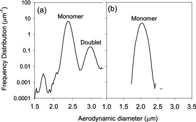
This study introduces an on-demand type IAG which has been developed at the National Institute of Advanced Industrial Science and Technology (AIST), Japan (Iida et al. Citation2010, Citation2011, Citation2012) and describes the structure and performance characteristics of the AIST-IAG as a monodisperse particle number standard. The AIST-IAG is intended for calibrating aerosol instruments in upper sub-micrometer to lower super-micrometer range. The IAG controls particle generation rates solely by the frequency of voltage pulses sent to its inkjet head. The most important advantage of the AIST-IAG over the VOAG is its ability to precisely control particle generation rates. In the VOAG, droplets are dispersed by a turbulent mixing to minimize the formation of doublets which would induce a broadening of particle size distributions. However, turbulence induces significant particle depositions, and the deposited fraction is higher than 50% (Mitchell and Waters Citation1986). Accordingly, the VOAG is not considered as a standard for particle number concentrations (ISO/TC24/SC4 Citation2009). compares a typical particle number based aerodynamic size distribution of the particles generated by the VOAG and the AIST-IAG. The VOAG-generated particles contain some doublets, and these doublets account for a small fraction of the total particle number. On the other hand, no doublets are seen in the size distributions of the AIST-IAG generated particles.
FIG. 1. Typical particle number based aerodynamic size distributions of the aerosol particles generated by (a) the VOAG and (b) the AIST-IAG. Particle material is NaCl. Aerodynamic particle sizer (APS, TSI-3220) was used; TOF bins of aerodynamic raw data were converted to particle sizes using the calibration data stored in the APS hardware. The original results in Iida et al. (Citation2012) were used with permission from the Japan Association of Aerosol Science and Technology.
One important application of the AIST-IAG is to use it as an aerosol particle number concentration standard in sub- to micrometer particle diameter range. The AIST provides calibration services for evaluating detection efficiencies of CPCs. A Faraday-cup aerosol electrometer (FCAE), in combination with a generator of size-classified singly-charged particles, is used as the primary measurement standard for the aerosol particle number concentration in Japan (Sakurai et al. Citation2006, Citation2008; Sakurai and Ehara Citation2010). The current upper limit of the particle diameter range of the AIST calibration service is 300 nm, and there is a need for extending the range to larger diameters up to micrometers. For example, OPC have been implemented to monitor various clean manufacturing environments. Pharmacopeias in EU and Japan demand monitoring of the total airborne particle number concentration in the particle diameter range above 0.5 and 5 μm in pharmaceutical manufacturing environment, and OPC manufactures need to validate the counting performance of the OPCs at these two sizes. Accordingly, an efficient method to calibrate the counting efficiency of OPCs up to ∼10 μm is needed. On the other hand, Yli-Ojanpera et al. (Citation2012) calibrated the detection efficiency of a TSI-3772 CPC over 10 nm to 10 μm range using the AIST-FCAE, the Single Charged Aerosol Reference (SCAR) (Yli-Ojanperä et al. Citation2010), and the AIST-IAG. The calibration results between the SCAR and the AIST-FCAE agreed well over the particle diameter range from 10 to 200 nm, the results between the SCAR and the AIST-IAG also agreed well over the particle diameter range from 200 nm to 1 μm. These results encourages the AIST-IAG to become a measurement standard for the aerosol particle number concentration within submicrometer to micrometer particle diameter range.
2. DESCRIPTION OF THE AIST-INKJET AEROSOL GENERATOR (AIST-IAG)
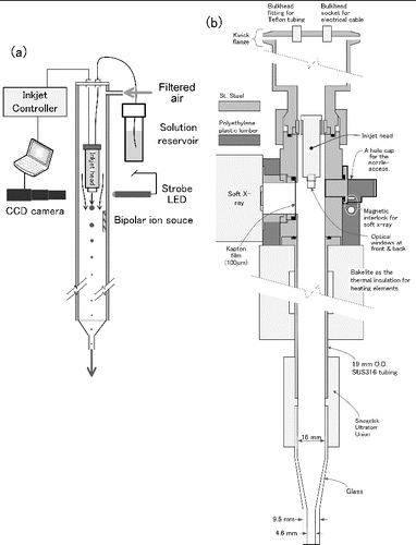
a and b are an overview and a simplified drawing of the AIST-IAG, respectively. Inkjet solutions are first prepared. The solution is dispensed as droplets using an inkjet head. The droplets are entrained by filtered carrier gas and subsequently electrically neutralized by a cloud of bipolar ions. Solvent content of the droplets is evaporated by a heating, and aerosol particles are formed. The following sections describe the structures of the AIST-IAG.
FIG. 2. (a) An overview and (b) simplified drawing of the AIST-IAG. This version uses a photoionizer as a bipolar ion source.
2.1. Droplet Generation
As shown in a the essential components of the inkjet hardware are inkjet head, a liquid reservoir, an inkjet controller, a CCD camera with a zoom lens, and a LED strobe. The inkjet head (MD-K series, Microdrop Technologies, Germany) has a glass nozzle surrounded by a tubular piezoelectric element. The exit diameter of a nozzle inside the inkjet head was 30 μm in this study.Footnote The inkjet controllers used in this study were uDropC-170 (Hantec, Japan) or IJK-200S (Microjet, Japan). shows an animation of droplets being generated from the nozzle tip.Footnote The AIST-IAG controls the particle generation rate by controlling the droplet generation rate of an inkjet head; therefore, a user must adjust the height of voltage pulses applied across the piezoelectric element to set the generation rate while preventing the formation of satellite droplets.Footnote
FIG. 3. Cutouts from an animation of the inkjet process inside the droplet generation region of the AIST-IAG. The velocity of ejected droplets was constant for a fixed pulse height. The velocities varied between 1∼1.6 m/s depending on the height of voltage pulses sent to the inkjet head.

A filtered gas forms a sheath flow around the inkjet head and carries the droplets downstream. The aerosol flowrate of the IAG can be controlled either by pulling the aerosol from the IAG exit or pushing particle-free carrier-gas from the inlet. Ultrapure water (UPW) and isopropyl alcohol (IPA) were used as the solvent of the inkjet solution in this study.Footnote The mass concentration of the solute in the solution is adjusted to control the size of the generated particles.
2.2. Electrical Neutralization and Evaporation
Droplets are neutralized by bipolar ions generated by either a 241Am radioactive source (3.0 MBq) or a photo-ionizer (Hamamatsu Photonics, L11757). Without electrical neutralization the number of charges on some of the droplets would reach the Rayleigh limit as the droplets evaporate, and small daughter droplets would fly out from the highly charged surface of mother droplets (Fernandez de la Mora Citation1996; Kim and Dunn Citation2010). Solvent content of the droplets evaporates, and the solute residue becomes a particle. The length and inner diameter of the evaporation tube used in this study were 430 mm and 16 mm, respectively. The wall temperature of the evaporation tube was set to 80°C and 40°C in this study when the UPW and IPA were used as the solvent of inkjet solution, respectively.
2.3. Volume Equivalent Diameter of the IAG Generated Particles
The diameter of particles generated by the IAG is controlled by changing the mass concentration of nonvolatile solute in an inkjet solution. Assuming the particle mass density is the same as the bulk density of the solute-material the volume equivalent diameter, , is given by
[1] where
is the average mass of a droplet,
is the mass concentration of a solute whose unit is the mass of solute per the mass of inkjet solution,
is the bulk density of the solute, and
is the particle diameter of solvent residue; nonvolatile impurities in the solvent become aerosol particle when no solute is added to an inkjet solution. The value of
strongly depends on the nozzle diameter of an inkjet head and physical properties of a solvent in an inkjet solution. Accordingly, the value of
was evaluated by measuring the change in the mass of the reservoir bottle for an inkjet solution,
, after continuously generating droplets for a certain length of time,
, at a fixed droplet generation rate,
. In this study, the value of
was set to 3 h, and the mass resolution of the microbalance for measuring the value of
was 0.1 mg. Then, the value of
was calculated by
[2]
3. THE METHODS OF EXPERIMENTS AND ANALYSES
3.1. Particle Generation Efficiency of the AIST-IAG
3.1.1. As a Function of Particle Sizes
The particle generation efficiency of the AIST-IAG, , is defined as the number of aerosol particles generated per each voltage pulse sent to a piezoelectric element of an inkjet head. The size dependence of the efficiencies was evaluated. a shows the experimental setup.
FIG. 4. The experimental setup for evaluating particle generation efficiencies of the AIST-IAG 9 (a) as a function of the particle sizes, and (b) as a function of the droplet generation rates.
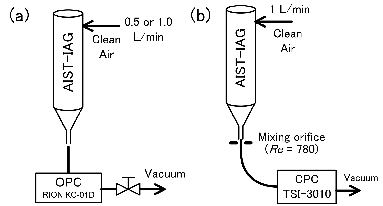
The aerosol flowrate through the IAG was set either at 0.5 or 1.0 L/min. The droplet generation rate was fixed at 100 droplets s−1. Solid particles made of sodium chloride (NaCl) and liquid droplets of a water soluble ionic liquid were generated. The volume equivalent diameters of the generated particles were 0.52, 0.81, 1.3, 2.0, 3.2, and 5.1, and 8.2 μm. The ionic liquid used was 1-ethyl-3-methylimidazolium trifluoromethanesulfonate (EMI-TFMS, CAS 145022-44-2), and their volume equivalent diameter was controlled over 0.4 to 10 μm range. An OPC (RION KC-01D) attached at the exit of the IAG counts the sampled particles for 1 min, and the particle counts were recorded continuously using data acquisition devices. The OPC is designed to count all the incoming particles whose diameters are approximately above 0.3 μm, and the sampling flowrate of the OPC was equal to the aerosol flowrate exiting the IAG.
In this study, the droplet generation rate is defined as the frequency of voltage pulses sent to an inkjet head. The ratio of the particle count rate measured by the OPC,
, to a droplet generation rate is defined here as the apparent particle generation efficiency,
.
[3] The apparent efficiency at a given size is the product of
and the particle counting efficiency of the OPC,
,
[4] and evaluating the value of
requires the value of
at the size.
The counting efficiency of the OPC was assumed to be consisting of two components; (I) the fraction of sampled particles that passed through a short straight tube followed by a flow focusing nozzle and its incident laser beam, , and (II) the fraction of sampled particles whose scattered light successfully recognized as a particle detection event by the OPC hardware.
[5] In short,
is the particle transport efficiencies inside the OPC. Their values were unknown therefore assumed to be unity in this study. The factor
is more commonly known as the coincidence correction factor. The method used to obtain the coincidence correction factor in this study is described in the online supplemental information (SI).
3.1.2. As a Function of Droplet Generation Rates
The AIST-IAG is capable of converting the generated droplets into aerosol particles within a certain range of its droplet generation rates. The minimum particle generation rate of the AIST-IAG was on the order of a few tens of droplets per second. Below this frequency a stable inkjet process could not be sustained. The maximum rate is determined by the time required to evaporate solvent from the droplets. Based on our experience a robust method to check the drying capability of the IAG was to prove that the IAG could generate residue particles consisting of nonvolatile impurities in the solvent continuously at same rate for several hours or longer. Accordingly, the particle generation rates of these residue particles were measured as a function of droplet generation rates. Particle size distribution of the evaporation residue of two solvents, UPW and IPA, were measured using a scanning electrical mobility spectrometer (SEMS) (Wang and Flagan Citation1990). The sizes of these residue particles were less than 200 nm.
b shows experimental setup. The actual particle generation rates at the IAG exit were evaluated using a TSI-3010 CPC whose nominal flowrate was 1 L/min. A mixing orifice was attached to the IAG exit to disperse the IAG-generated particles. The diameter of the orifice was 1.7 mm, and the resulting flow Reynolds number was 780. The length and inner diameter of the flexible conductive tube to the CPC were 320 mm and 5 mm, respectively. Outside-wall temperature of the evaporation tube was controlled at 80°C and 40°C when ultrapure-water and IPA was used as the inkjet solution, respectively.
Counting rate of the CPC closely matched the droplet generation rate only when UPW or IPA droplets evaporated completely and formed residue particles before reaching the orifice. Incomplete evaporation caused inertial depositions of the droplets during transport and lead to lower and unstable particle count rates. The apparent efficiencies is the product of , the particle transport efficiencies through the orifice,
, and the particle counting efficiency of the CPC,
,
[6] The
was considered to be size independent over the size range of the residue particles, and
= 0.95 ± 0.013 (k = 2) was used. This assumption is based on the particle detection efficiencies of the CPC within 30–200 nm particle diameter range, which was calibrated using the primary number concentration standard at AIST.Footnote
Since the Stokes number of the residue particles through the mixing orifice was on the order of 10−3 no inertial deposition was expected to occur. Accordingly, the value of
was assumed to be 1. Finally, the
was calculated by
.
3.2. Particle Size Range and Width of the Particle Size Distribution
The sizes of particles generated by the AIST-IAG are controlled by changing the mass concentration of solute in inkjet solutions. This study focuses on demonstrating the ability of the IAG to produce monodisperse particles in solid or liquid phase using water as the solvent of inkjet solutions, and solid NaCl particles and liquid EMI-TFMS particles were generated. The size distributions of the generated particles were measured using an APS (Model 3321, TSI, USA). An aerodynamic-size distribution of the IAG-generated particles and that of the size-standard polystyrene latex (PSL) spheres were compared to qualitatively evaluate the width of size distribution of the IAG-generated particles. The comparison was performed at the size around 2 μm. The certified particle diameter of the PSL spheres and the coefficient of variation of the size distributions were 2.01 μm and 2.8%, respectively (JSR Life Science, Japan).
The widths of particle size distribution of the IAG-generated particles in submicrometer range were evaluated quantitatively. The electrical mobility distribution of the EMI-TFMS particles were measured by slow SEMS scans, which spent 5 min for up scans and 5 min for down scans. The particle size distributions were obtained by inverting the measured electrical mobility distributions using the algorithm of Stolzenburg (Citation1988). The differential mobility analyzer (DMA) was assumed to be operating under a stepping mode, and the transfer function of the DMA has a perfect triangular shape in the electrical mobility space.
3.3. Reproducibility of Particle Sizes
3.3.1. Volume Equivalent Diameter
Using a continuous inkjet-based aerosol generator (e.g., the VOAG) the volume equivalent diameter of generated particles can be precisely controlled since a user can precisely know the average mass or volume of the droplets by setting the droplet generation rates and the flowrate of a solution through the micro-orifice within an appropriate range. Unfortunately, this is not the case for the AIST-IAG since it uses an on-demand inkjet device. The value of cannot be known unless measurements are made using a microbalance as described in Section 2.3. It is impractical to carry out the measurement before every use. Accordingly, it is important to quantitatively evaluate the reproducibility of the volume equivalent diameter of the IAG generated particles. The values of
were not directly measured. Instead an error propagation analysis of EquationEquation (1)
[1] was performed, and the standard uncertainty of
was evaluated and used as the measure of the reproducibility.
From the definition of given in EquationEquation (1)
[1] the relative standard uncertainty (RSU) of
, where
is the standard uncertainty of
, was estimated by
[7] The values in the parenthesis on the right hand side of the equation were defined as the RSU of
with respect to an independent variable X
[8] and the expressions for
,
, and
are given by
[9a]
[9b]
[9c]
[9d] The values of
,
, and
were estimated and compared.
First, the RSU of ,
, was evaluated experimentally. The source of variations considered were chemical identities of solutes and their concentrations in inkjet solutions since they can influence physical properties such surface tension, viscosity, and density of the solution. The most significant random factor is temperature drifts inside the IAG and accumulation of contaminants inside the inkjet nozzle since physical properties of liquid are temperature dependent. Accumulation of contaminants inside the nozzle alters the critical geometries of the inkjet nozzle therefore potentially change the amount of the solution dispensed per each pulse.Footnote
Either NaCl or EMI-TFMS was used as solute material, and inkjet solutions with three different concentrations were prepared. Concentrations of NaCl were 1.629, 202.4, and 21830 ppm (the mass of solute per the mass of solution) and their corresponding
were 0.40, 1.9, and 8.9 μm, respectively. The concentrations of EMI-TFMS were 2.214, 276.2, and 34150 ppm and their corresponding
were 0.51, 2.4, and 12 μm, respectively. The microbalance used to obtain the droplet mass was Mettler Toledo XP-504DR. The expanded uncertainty written on the calibration certificate of the microbalance was ±1.0 mg. The measurements were repeated five times at each condition. Consequently, the input matrix for the ANOVA consisted of two solute types, three solute concentrations, and five repeated measurements.
The droplet generation rate was not included as a variable of the uncertainty evaluation of md since the effect was expected to be small. The effect of droplet generation rates on md was analyzed by performing ANOVA. Ultrapure-water was used as an inkjet solution; therefore, interactions between the solute concentration and droplet generation rates were neglected. The input matrix to ANOVA consisted of six replicates at three different frequency ranges (100–200 s−1, 500 s−1, and 900–1000 s−1). The ANOVA-results indicated that the droplet mass did not vary significantly across droplet generation rates.
Second, the RSU of the particle diameter of the nonvolatile impurities, , were evaluated. The size distributions of
were measured using SEMS while the IAG was operating continuously for seven hours. Five measurements were taken per one hour on average. The value of
was approximated by the C.V. among the geometric mean diameters of the measured size distributions.Third, the RSU of the mass concentration of a solute in an inkjet solution
was roughly estimated. The measurement of the solute or solution mass using a microbalance was considered as the only source of uncertainties of
in this approach. The details of the procedure are given in the SI.
3.3.2. Aerodynamic Diameter
Reproducibility of the particle sizes of IAG generated particles were evaluated experimentally. Particles sizes corresponding to a known were measured using a TSI-3321 APS, the symbol
was used to denote this size. First, the time-of-flight (TOF) channels of the APS, which was denoted by a symbol τ, were calibrated as a function of sizes of the PSL spheres. The particle diameters of those PSL spheres in micrometer were 0.352, 0.458, 0.603, 0.814, 1.008, 2.005, 3.21, 4.992, 7.123, 10.28, and 15.62.Footnote
Second, NaCl and EMI-TFMS particles with a known
between 0.5 to 10 μm were generated, and a representative τ corresponding to each
was measured. Third, the value of
corresponding to
was obtained from the relationship between the sizes versus τ of the PSL spheres.Footnote
Technically, the values of
evaluated in this experiment was the emulated sizes of the PSL spheres that gave the same magnitude of TOF signal as the IAG-generated particles with a known
. The standard uncertainties of the interpolated
were estimated by
[10] The slope on a logarithmic scale
was estimated from the relationship between the sizes versus τ of the PSL spheres. The values of the slope generally increased as the size decreased since the relative change in the particle size increases as τ decreases. The ratio
is the RSU of the measured τ. This τ refers to τ of the IAG generated particles having a known
. The RSU was estimated by the C.V. among five separate experiments for evaluating the reproducibility.
4. RESULTS AND DISCUSSIONS
4.1. Particle Generation Efficiency of the AIST-IAG
4.1.1. As a Function of Particle Sizes
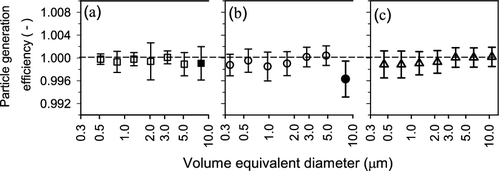
a–c shows the particle generation efficiencies of the IAG as a function of particle sizes. Special attention is given to the filled data points which are for NaCl particles at 8 μm. Coincidence correction assuming a Poisson process is applied to these data points (see the SI). The particle generation efficiencies were above 99.5% within the size range investigated. The error bars represent the standard uncertainties and details of the evaluation procedure are given below.
FIG. 5. Size dependence of particle generation efficiencies of the AIST-IAG when droplets are generated at 100 droplets/s for 60 s. Filled symbols indicate that a coincidence correction was applied to these data points. Particle material and aerosol flowrates of the AIST-IAG in each figure are (a) NaCl and 0.5 L/min, (b) NaCl and 1.0 L/min, and (c) TFMS and 1.0 L/min, respectively. The error bars represent the standard uncertainty (k = 1).
It was assumed that the uncertainty of the consisted of two components. The first component was the actual rate of aerosol particles exiting from the IAG,
, and the second component was the transport efficiencies inside the OPC. Combining EquationEquations (4)
[4] and (5) and solving for
gives
[11] Coincidence correction factors were evaluated; therefore, indicated particle count rates were corrected to obtain the value of
assuming that the transport efficiencies inside the OPC was unity (
)
[12] As described in the SI, the coincidence correction factor was not unity when the generated size and particle material were 8.2 μm and NaCl, respectively. Combining EquationEquations (11)
[11] and (12) gives
[13] Uncertainty of
was evaluated by performing an error propagation of EquationEquation (13)
[13] . Frequency of voltage pulses sent to the inkjet head was occasionally measured and known to be reproducible within ±0.0001 s−1 when the droplet generation rate of the IAG was 100 s−1. The RSU of the droplet generation rate was expected to be less 10−5, which was small therefore neglected. The uncertainty of the
was estimated by
[14] where the symbol
denotes a standard uncertainty.
The second term in EquationEquation (14)[14] , which is for the transport efficiency inside the OPC, accounts for the uncertainty in
caused by that true value of
were unknown. Following ISO/IEC Guide 98 (JCGM/WG1 Citation2008), which is a guide for expressing measurement uncertainties, it was assumed that
is uniformly distributed between the value of
and unity. The variance of
under the worst case scenario was calculated in this study by using
as the expected value of
,
[15] The first term in EquationEquation (14)
[14] accounts the variations of
. In this study, variations across three elements were considered and evaluated: particle diameters,
, experiments performed on different day,
, and continuously repeated measurements within a relatively short time,
. Analysis of variance (ANOVA) was performed to evaluate these three sources simultaneously and quantitatively when aerosol flowrate of the IAG and particle material were 0.5 L/min and NaCl, respectively. At each particle size, the experiments were performed on five different days, and the measurements were repeated at least 14 times on each day. Consequently, the matrix of measured particle count rates consisted of three dimensions: seven particle sizes, five days of measurements, and 14 times of repeated measurements, and the matrix were used as the input of the ANOVA. The resulting uncertainty expression for the rate of aerosol particles exiting from the IAG was
[16] where the value of
was calculated by taking an average among all input values contained in a three dimensional input matrix. The ratio inside each parenthesis was expressed as RSU or coefficient of variations,
, and the uncertainty expression for the
and
were estimated by
[17a]
[17b] The value of
needed to evaluate the value of
in EquationEquation (15)
[15] was the average transport efficiencies across all particle sizes,
, which is calculated by
assuming
.
summarizes the uncertainty analysis on the particle generation efficiencies of the IAG when its aerosol flowrate was set at 0.5 L/min and the particle material was NaCl. The SI shows the numerical output of ANOVA, and explains how the ANOVA-output were processed to obtain the values in . The analysis suggest that 95% confidence interval of the particle generation efficiency were 0.998 ± 0.006 within the size range investigated.
Table 1. Summary of the uncertainty analysis of the particle generation efficiency of AIST-IAG when the aerosol flowrate and droplet generation rates were set at 0.5 L/min and 100 s−1, respectively
Error bars of size dependent shown in were evaluated as follows. In this study, the day-to-day variations was not evaluated when the aerosol flowrate of the IAG was 1.0 L/min since it was too labor intensive to obtain three dimensional dataset to perform ANOVA. Therefore, it was assumed that the value of
evaluated under 0.5 L/min aerosol flowrate represented the day-to-day variation under 1.0 L/min as well. The standard uncertainty for the particle generation efficiencies of the IAG at given particle diameter Dp,
, was evaluated by
[18a]
[18b] where
was evaluated by calculating the coefficient of variation (C.V.) across the continuously measured values of
within a day at a given particle diameter, and the value of
was calculated by taking an average at the size. The average particle generation efficiencies at given particle size,
, was calculated by
assuming
, and the value was substituted into EquationEquation (15)
[15] to evaluate the value of
. Finally, the error bars shown in were calculated by
.
4.1.2. As a Function of Droplet Generation Rates
shows the particle generation efficiencies of the AIST-IAG as a function of its droplet generation rates.
FIG. 6. Particle generation efficiencies of the AIST-IAG as a function of droplet generation rates. The error bars represent the expanded uncertainty (k = 2) of the average values. (a) UPW and (b) IPA were used as the inkjet solution; therefore, the particle material in these experiments was evaporation residue of these solvents. Outside-wall temperature of the evaporation tube was set at 80°C and 40°C when ultrapure-water and IPA was used as the inkjet solution, respectively. Results shown in (b) were published in Iida et al. (Citation2012), and the original results were used with permission from the Japan Association of Aerosol Science and Technology.
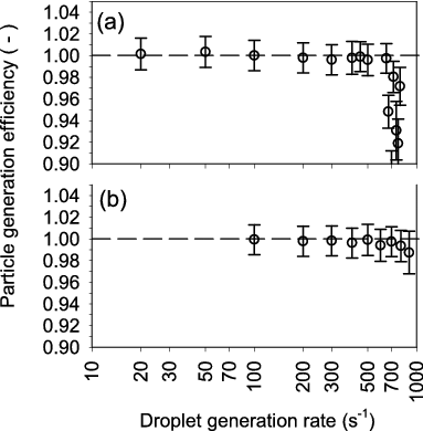
A droplet generated by each voltage pulse was converted to an aerosol particle inside the IAG when generation rates of UPW droplets were within 20–500 s−1, and the rates of IPA droplets were within 100–900 s−1. It is most likely that upper limits of the observed range were set by net diffusive flux of solvent vapor from the evaporating droplets. At generation rates beyond 500 s−1 less than 3∼4 droplets would be able to fit in a void space between two neighboring droplets along the tube axis. As the void space decreases diffusive motions of vapor molecules along the axis between two neighboring droplets cancel each other reducing the net flux of evaporating vapor from the droplets. Since the aerosol flowrate of the IAG in this experiments was 1 L/min it was concluded that the IAG controlled the particle number concentration at its exit within 1.2–30 cm−3 and 6.0–54 cm−3 when UPW and IPA were used as the solvent of inkjet solutions, respectively.
4.2. Particle Size Range and Width of the Particle Size Distribution
shows the aerodynamic size distributions of IAG-generated NaCl (solid) and EMI-TFMS (liquid) particles in the particle diameter range from 0.5 to 20 μm.
FIG. 7. Number based size distribution of solid and liquid particles generated by the AIST-IAG as a function of aerodynamic diameter. (a) The solid particles consisting of NaCl, and (b) the liquid droplets consisting of EMI-TFMS. The original results in Iida et al. (Citation2012) were used with permission from the Japan Association of Aerosol Science and Technology.
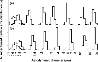
The result proves that AIST-IAG generated monodisperse particles in solid and liquid phases over micrometer range without generating satellite particles. a compares the aerodynamic size distribution of NaCl particles and PSL spheres in micrometer range.
FIG. 8. (a) Number based particle size distribution as a function of aerodynamic diameter. PSL spheres with average diameter and coefficient of variation are 2.01 μm and 2.8%, respectively, and NaCl particles generated by the AIST-IAG using 108 mg/L water-based NaCl solution. A TSI Model 3320 APS spectrometer was used. (b) Number based size distribution of EMI-TFMS liquid particles generated by the AIST-IAG. The size axis is normalized by the number average particle diameter of the distribution which was 505 nm. The electrical mobility distributions measured using SEMS were inverted to obtain the actual particle size distribution.
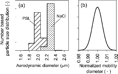
The C.V. of aerodynamic size distributions were 4.3% and 1.9% for the PSL spheres and the NaCl particles, respectively. These results indicated that NaCl particles generated by the IAG were as monodisperse as the PSL spheres. However, these NaCl particles were not perfectly spherical, and morphologies of the particles may not be the same over 0.4 to 10 μm particle diameter range. shows scanning electron microscopy (SEM) images of IAG-generated NaCl particles.
FIG. 9. Example SEM images of NaCl particles generated by the AIST-IAG. The mass concentration of NaCl were (a) 108 mg/L and (b) 1.00 × 10⁴ mg/L, respectively.
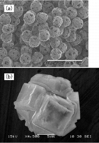
As the images indicate these particles were all agglomerates each consisting of cubic NaCl crystals. Solvent content of solution droplets was forced to evaporate within a relatively short residence time inside the evaporation tube of the IAG inducing the nucleation of dissolved ions at multiple sites within the droplets.
b shows the actual particle size distribution of the IAG-generated EMI-TFMS liquid particles obtained by inverting electrical mobility distributions of these particles. The size axis was normalized by the average mobility diameter, which was 505 nm, of the distribution. The relative standard deviations of the inverted size distribution were all less than 1% indicating that these liquid droplets were highly monodisperse.
4.3. Reproducibility of Particle Sizes
4.3.1. Volume equivalent diameter
shows measured average mass of a droplet as a function of
of the IAG generated particles.
FIG. 10. Average mass of a droplet as a function of volume equivalent diameter of the IAG generated particles. Measurement of the droplet mass was repeated for five times at each volume equivalent diameter, and the error bar in the figure is standard deviation calculated using these five values.
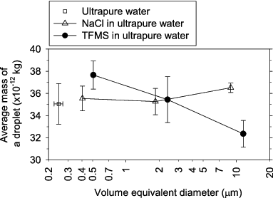
Measurements of were repeated for five times at each
, and each error bar in the figure is the standard deviation calculated using these five values. It appears that
decreased when more EMI-TFMS was added to the solution. On the other hand, adding similar amount of NaCl did not change
significantly. The SI shows numerical output of the ANOVA, and explains in detail how the ANOVA-output were processed. The ANOVA results identified that interactions between particles sizes versus solute types were significant, which indicates that the size dependence of
was affected by whether the solute material was solid or liquid. A symbol
is used here to represent the RSU of the interactions, and its value was 6.1%. The RSU due to the variation across repeated measurements and other sources of random error is represented by a symbol
, and its value was 4.5%. Overall RSU of
is given by
[19] where n is the number of measurements. If n = 1 the value of
is 7.5%.
The SEMS measurements on the particle size distribution of nonvolatile residue showed that the average of was 246 nm, and its RSU,
, was 9.1%. The RSU of
,
, were small. The values of
ranged from 0.040 to 0.042% over the evaluated range of
. It is noted that the
in this study did not include other sources of random errors associated with manual dilution process.
shows the RSU of with respect to each uncertainty factor, which were
,
, and
, as a function of
.
FIG. 11. Comparison of three uncertainty factors included in the error propagation analysis of of the IAG-generated particles. The relative standard uncertainties (RSU) of
with respect to each uncertainty factor are shown. Combined RSU of
are also shown. The number of the measurement of
was assumed to be one.
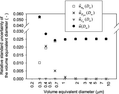
Overall RSU of is also shown. In this example, it was assumed that
was measured only once. The results clearly showed that the uncertainty of
dominated over the other factors in the size range above 0.5 μm, and the RSU of the
was about 2.5% in this size range. Uncertainty in
starts contributing significantly to
at the sizes below 0.4 μm, indicating that the minimum particle size that the IAG can control was around 0.4 μm. It was concluded that 95% of the time the AIST-IAG would reproduce
within ±5% of the expected value.
4.3.2. Aerodynamic Diameter
shows the measured corresponding to
of the IAG-generated particles.
Table 2. The relationship between the particle sizes measured by the APS, DAPS, and the volume equivalent particle diameter of the IAG-generated particles, Dve
It is noted that the values of may depend on evaporation temperature of the IAG and relative humidity downstream of the IAG exit. The values in the parenthesis are the C.V. of
among five separate measurements. The C.V. of
ranged from 2.0 to 5.8% and 1.0 to 3.6% when NaCl particles and TFMS droplets were generated, respectively. These experimental values were close to the theoretically estimated RSU of
implying that the reproducibility of the droplet mass affected the reproducibility of the particle sizes the most. The C.V. of
were smaller or greater than the RSU of
at some sizes. The most likely source of the variation was that the error in the measured slope between the sizes of PSL spheres and TOF channels on a logarithmic scale, which is
in EquationEquation (10)
[10] . The parameter was the scale factor for propagating the C.V. of τ of the IAG generated particles to obtain the RSU of
. The relationship between
versus τ was evaluated only once in this study; therefore, the slope likely have some error.
The values of were consistently larger than
. The bulk density of NaCl (≈2.17 g/cm3) and EMI-TFMS (≈1.39 g/ml at 25°C) are larger than the mass density of PSL spheres (≈1.05 g/cm3); therefore, APS would see these particles as larger PSL spheres than
.Footnote
The effective densities of the NaCl particles were expected to be smaller than the bulk density of NaCl since these particles tended to develop porous structures as already shown in . Fluctuations in the temperature inside the evaporation tube of the IAG potentially cause the variation in the morphology of the NaCl particles among different experiments, and this was a potential reason for that the C.V. in sizes were larger for the solid particles than liquid particles.
5. CONCLUSION
AIST-IAG can generate highly monodisperse aerosol particles in solid or liquid phase in the particle diameter range from 0.3 to 20 μm at precisely known particle generation rates. The particle generation efficiencies of the IAG were evaluated in the particle diameter range from 0.4 to 10 μm when the droplet generation rate was set at 100 s−1 and the aerosol flowrates were set at 0.5 and 1.0 L/min. Within the ranges of the particle sizes and flowrates 95% confidence interval of the particle generation efficiency were 0.998 ± 0.006. The efficiencies were also evaluated as a function of the droplet generation rates of the IAG when either ultrapure-water or IPA was used as the solvent of inkjet solutions. The efficiencies remained near unity when the generation rates of water droplets and isopropanol droplets were within 20–500 s−1 and 100–900 s−1, respectively. In this study, we focused on the generation of water-soluble particles. NaCl and ionic liquid (EMI-TFMS) were used to generate solid and liquid particles, respectively. The relative standard deviations (or the C.V.) of the particle size distributions of the NaCl particles were a few percent, and the aerodynamic size distribution measurements shows that the IAG-generated particles were as monodisperse as the size standard PSL spheres. The analysis on the mobility distribution of TFMS particles generated by the IAG showed that the C.V. of the particle size distribution was about 1%. Reproducibility of the IAG with respect to the sizes of the generated particles was investigated. The uncertainty analysis on the factors affecting of the IAG-generated particles indicated that 95% of the time AIST-IAG would reproduce
within 5% of the expected value. The uncertainty of the average droplet mass dominated the uncertainty of
. The droplet mass had a strong interaction with
when ionic liquid was used as the solutes of an inkjet solution. On the other hand, such interaction was not significant when NaCl was used. Size-reproducibility of the IAG-generated particles was evaluated experimentally by measuring their particle size distributions within the particle diameter range from 0.5 to ∼10 μm range. TSI 3321 APS was used. Coefficient of variation of
were less than 6% and 4% when NaCl particles and EMI-TFMS droplets were generated, respectively. The results indicated that sizes of the liquid droplets were more reproducible than sizes of the solid particles.
Our important future work is to develop a technique to create uniform concentration profile over the cross section of a tube when the IAG generated particles are sampled into an OPC. Depending on the optical design of an OPC its counting efficiencies may depend on at which portion of the incident light the sampled particles intersected. For this reason, particle concentration over a cross section of the OPC's sampling inlet should be uniform when counting efficiencies of the OPC are being evaluated. On the other hand, when aerosol particles are exiting from the IAG the particle concentrations over a circular cross section of the exit are nonuniform. Particles are rather concentrated along the axis when the particles are sampled into an OPC unless aerosol naturally mixes inside the inlet region of the OPC. Accordingly, it is important to develop a technique to disperse the IAG-generated aerosol particles to a sufficient degree while preserving the number of aerosol particles.
SUPPLEMENTAL MATERIAL
Supplemental data for this article can be accessed on the publisher's website.
Supplementary Material
Download Zip (257 KB)ACKNOWLEGMENTS
The Ministry's support is greatly acknowledged. Authors are indebted to Dr. Hajime Matsumoto at Research Institute for Ubiquitous Energy Devices AIST for sharing his extensive knowledge on ionic liquids.
FUNDING
This research was partly supported by the Environment Research and Technology Development Fund (RF-1001) of the Ministry of the Environment, Japan.
Notes
1 Each individual nozzle had its own characteristics even though the nominal nozzle diameter was the same. The diameter of generated droplets among different nozzles varied between 40–50 μm for water based solutions.
2 The velocity of droplets when they were just generated was constant for a fixed pulse height. The velocity varied between 1∼1.6 m/s depending on the height of voltage pulses sent to the inkjet head.
3 The width of the voltage pulse, whose unit is time, is directly related to half period of liquid swinging inside an inkjet nozzle. An optimum value is found by adjusting the pulse width which maximizes droplet velocity. The pulse width is usually fixed at a constant value for a given inkjet nozzle and solution type. The height of the voltage pulse controls how strongly liquid inside a nozzle is pulled backward before releasing the liquid column forward. Therefore, the pulse height affects the number of droplets ejected from the nozzle tip per pulse. Accordingly, a user must adjust the pulse height or at least check before each experiment to ensure only one droplet is produced per pulse by looking at the animation of droplet generation process.
4 The total organic carbon (TOC) of the ultrapure water was less than 5 ppb, and the purity of the IPA was 99.9% according to its specifications.
5 The detection efficiencies evaluated by the primary standard are based on the ratio of the concentration indicated by a commercial CPC to the value measured using the AIST-FCAE. Since the CPC uses its nominal flowrate for calculating particle number concentrations the error in the flowrate is part of the detection efficiency. The detection efficiency used in this article was already corrected for the error; therefore, the efficiency only accounted for the particle counting capability of the CPC.
6 Accumulation of contaminants inside an inkjet nozzle is usually identified by two effects. Amplitudes of the voltage required to sustain an inkjet process become higher than a normal value. Trajectories of the droplets become less straight along the axis. We recommend using acetone for a regular cleaning and avoid any risk of precipitation when chemically different solvents are mixed. Push and pull acetone through the nozzle while applying voltage pulses to the inkjet head. If the nozzle is severely clogged one needs to push special cleaning liquid from the nozzle tip toward its inlet. We recommend using a cleaning agent for silicon wafer. Dilute the cleaning agent to reduce its viscosity.
7 The sizes from 0.352 to 2.005 μm and from 3.21 to 15.62 μm were JSR-STADEX series and JSR-Dynosphere series, respectively. Sizes including 2.005 μm and below were aerosolized by atomizing diluted liquid suspensions of the PSL spheres, and a differential mobility analyzer (DMA, TSI Inc. Model-3080) was used to extract the PSL spheres up to 1.008 μm. Sizes including 3.21 μm and above were aerosolized using a small scale powder disperser (SSPD, Model 3433, TSI).
8 The value of corresponding to a τ of the IAG generated particles was obtained by linearly interpolating between two data pairs of the logarithm of PSL sizes versus the logarithm of τ.
9 Previous studies showed that aerodynamic diameter measured by TSI-3300 APS were smaller than volume equivalent diameter when sampled particles were liquid and their diameter were larger than about 5 μm because liquid particle deformed when these particles experience drag forces inside the APS (Mulholland et al. Citation1985; Baron Citation1986; Griffiths et al. Citation1986). The trend was not seen in our results, and its reason was not investigated further since the major objective of our measurements was to evaluate the reproducibility of the generated sizes.
REFERENCES
- Baron, P. A. (1986). Calibration and Use of the Aerodynamic Particle Sizer (APS 3300). Aerosol Sci. Technol., 5:55–67.
- Bemer, D., Fabries, J. F., and Renoux, A. (1990). Calculation of the Theoretical Response of an Optical Particle Counter and Its Practical Usefulness. J. Aerosol Sci., 21:689–700.
- Berglund, R. N., and Liu, B. Y. H. (1973). Generation of Monodisperse Aerosol Standards. Environ. Sci. Technol., 7:147–153.
- Bottiger, J. R., Deluca, P. J., Stuebing, E. W., and Vanreenen, D. R. (1998). An Ink Jet Aerosol Generator. J. Aerosol Sci., 29:S965–S966.
- Cao, R., Tohno, S., Shino, T., Nishiyama, F., Kunimura, S., Kawai, J., et al. (2012). Design and Performance of a Cascade Impactor, MAIS-10. Earozoru Kenkyu, 27:385–393.
- Chen, B. T., Fletcher, R. A., and Cheng, Y. S. (2011). Calibration of Aerosol Instruments, in Aerosol Measurement: Principles, Techniques, and Applications, P. A. Baron, P. Kulkani, and K. Willeke, eds., John Wuket & Sons, Hoboken, NJ.
- Fernandez de la Mora, J. (1996). On the Outcome of the Coulombic Fission of a Charged Isolated Drop. J. Colloid Inter. Sci., 178:209–218.
- Griffiths, W. D., Iles, P. J., and Vaughan, N. P. (1986). The Behavior of Liquid Droplet Aerosol in an APS 3300. J. Aerosol Sci., 17:921–930.
- Gucwa, K. J., Lang, M. C., Moharreri, A., and Dhaniyala, S. (2009). Vibrating Orifice Aerosol Generator: Droplet Generation Frequencies revisited, in AAAR 28th Annual Conference, Minneapolis, MN, USA.
- Hill, S. C., Pinnick, R. G., Niles, S., Pan, Y.-L., Holler, S., Chang, R. K., et al. (1999). Real-Time Measurement of Fluorescence Spectra from Single Airborne Biological Particles. Field Anal. Chem. Technol., 3:221–239.
- Iida, K., Sakurai, H., Saito, K., and Ehara, K. (2011). Development of Inkjet Aerosol Generator, in American Association of Aerosol Research 30th Annual Conference, Orlando, FL, USA, 6A.5, Oral Presentation.
- Iida, K., Sakurai, H., Saito, K., and Ehara, K. (2010). An Inkjet Aerosol Generator for Calibrating Particle Counters, in International Aerosol Conference 2010 Helsinki, Helsinki, Finland, Poster Number P1E59.
- Iida, K., Sakurai, H., Saito, K., and Ehara, K. (2012). Aerosol Generation Using the Inkjet Technology. Earozoru Kenkyu 27:341–349.
- ISO/TC24/SC4 (2009). ISO 21501–4: Determination of Particle Size Distribution – Single Particle Light Interaction Methods – Part 1: Light Scattering Aerosol Spectrometer, International Organization for Standardization, Geneva, Switzerland.
- JCGM/WG1 (2008). ISO/IEC Guide 98–3:2008 Uncertainty of Measurement – Part 3: Guide to the Expression of Uncertainty in Measurement (GUM:1995), International Organization for Standardization, Geneva, Switzerland.
- Kesavan, J., Bottiger, J., Schepers, D., and McFarland, A. (2012). Calibration of the Aerodynamic Particle Sizer Using an Ink Jet Aerosol Generator (IJAG), in AAAR 31st Annual Conference Minneapolis, Minnesota, USA, Poster Number: 2IA.7.
- Kesavan, J. S., Bottiger, J. R., Schepers, D. R., and McFarland, A. R. (2013). Comparison of Particle Number Counts Measured with an Ink Jet Aerosol Generator and an Aerodynamic Particle Sizer. Aerosol Sci. Technol., 48:219–227.
- Kim, O. V., and Dunn, P. F. (2010). Controlled Production of Droplets by In-Flight Electrospraying. Langmuir, 26:15807–15813.
- Kinney, P. D., and Pui, D. Y. H. (1995). Inlet Efficiency Study for the TSI Aerodynamic Particle Sizer. Part. Part. Syst. Char., 12:188–193.
- Liu, B. Y. H., Berglund, R. N., and Agarwal, J. K. (1974). Experimental Studies of Optical Particle Counters. Atmos. Environ. (1967) 8:717–732.
- Liu, B. Y. H., and Pui, D. Y. H. (1981). Aerosol Sampling Inlets and Inhalable Particles. Atmos. Environ. (1967) 15:589–600.
- Marple, V. A., and Olson, B. A. (2011). Sampling and Measurement Using Inertial, Gravitational, Centrifugal, and Thermal Techniques, in Aerosol Measurement: Principles, Techniques, and Applications, 3rd ed., P. Kulkarni, Baron, P. A., and Willeke, K. eds. John Wiley & Sons, New Jersey, 129.
- Mitchell, J. P., and Waters, S. (1986). Improvements to the Vibrating Orifice Aerosol Generator (VOAG) for the Production of Methylene Blue Particles. J. Aerosol Sci., 17:556–560.
- Mulholland, G., Hembree, G., and Hartman, A. (1985). Sizing of Polystyrene Spheres Produced in Microgravity. NBSIR, Nat. Bureau Standands 84–2914.
- Sakurai, H., and Ehara, H. (2010). Evaluation of Uncertainties in Femtoampere Current Measurement for the Number Concentration Standard of Aerosol Nanoparticles Meas. Sci. Technol., 22:024009–024019.
- Sakurai, H., Ehara, K., Tajima, N., and Fukushima, N. (2006). Development and Evaluation of the Primary Calibration Standard for the Aerosol Number Concentration, in 7th International Aerosol Conference, St. Paul, Minnesota, USA, 541.
- Sakurai, H., Saito, K., and Ehara, K. (2008). Japan's National Standard for Aerosol Particle Number Concentration, in 27th American Association for Aerosol Research, Orlando, FL, USA, 152.
- Stolzenburg, M. R. (1988). An ultrainfe Aerosol Size Distribution Measuring System, in Department of Mechanical Engineering, University of Minnesota, Minneapolis, Minnesota, USA.
- Volckens, J., and Peters, T. M. (2005). Counting and Particle Transmission Efficiency of the Aerodynamic Particle Sizer. J. Aerosol Sci., 36:1400–1408.
- Wang, S. C., and Flagan, R. C. (1990). Scanning Electrical Mobility Spectrometer. Aerosol Sci. Technol., 13:230–240.
- Yli-Ojanperä, J., Mäkelä, J. M., Marjamäki, M., Rostedt, A., and Keskinen, J. (2010). Towards Traceable Particle Number Concentration Standard: Single Charged Aerosol Reference (SCAR). J. Aerosol Sci., 41:719–728.
- Yli-Ojanpera, J., Sakurai, H., Iida, K., Makela, J. M., Ehara, K., and Keskinen, J. (2012). Comparison of Three Particle Number Concentration Calibration Standards Through Calibration of a Single CPC in a Wide Particle Size Range. Aerosol Sci. Technol., 46:1163–1173.
