
Abstract
We investigate the formation of ultrathin nanofibers (UNFs) with diameters below 20 nm by electrospinning Nylon-6 solution with various processing parameters. It is found that the UNF density and morphology are highly dependent on the solution concentration and age, collecting distance, and ambient humidity. The sequence that ribbon-like fibers are stretched by the electric force, followed by rapid phase separation of the splitting film is proposed as a formation mechanism of the UNFs. Based on the morphological study, a model of hexagonal nets is developed in order to estimate the filtration efficiency by the UNF structure. The estimated efficiency due to the UNFs is then combined with the contribution from the un-split nanofibers (NFs) to compute the total filtration efficiency and pressure drop for each of the electrospun media by applying a layered multiple zone model. The filtration performance of the electrospun media against nanoparticles is evaluated using the quality factor and specific filtration performance index, weighed against the pressure drop and basis weight of the media, respectively. Our results show UNFs are advantageous when high filtration efficiency is required and low weight is desired and/or little space is available for the filter media.
Copyright 2014 American Association for Aerosol Research
INTRODUCTION
Nonwoven nanofiber media have gained popularity in applications such as wound dressing, electrodes, sensors, catalysts, drug carriers, tissue scaffolds, battery/cell and capacitor, and filters (Lu and Ding Citation2008; Wang et al. Citation2013). Nanofibers have excellent properties including high surface area to volume ratio, high porosity, flexibility in surface functionalities, and superior mechanical properties. Thus, they could provide a greater filtration efficiency and higher performance than conventional fibrous filters (Wang et al. Citation2008a,Citationb). In addition, the dust cake that built up on the surface of filter media can be easily cleaned off, to elongate the filter life (Wang et al. Citation2008a). The electrospinning process is known as a relative quick and simple way to fabricate sub-micro to nanoscale fibers from a variety of materials (Yao et al. Citation2010), thus, it has become increasingly attractive in separation technology. A number of studies have been performed, focusing on the formation, morphology, and evaluation of the filtration properties of various electrospun media. The protection function of the nanofibers/fabric was tested against airborne potassium iodide particles in the range 1–5 μm (Gibson et al. Citation2001), chemical warfare agents (Schreuder-Gibson et al. Citation2002), and liquids (Lee and Obendorf Citation2006). Wang et al. (Citation2008a,Citationb) measured the filtration efficiency of nanofiber filters with diameter less than 200 nm for airborne 3–780 nm particles and developed a numerical model that successfully estimated the filtration efficiency.
Since 2006 (Ding et al. Citation2006), researchers have been able to produce electrospun media composed of ultrathin nanofibers (UNFs) from a variety of polymer materials by optimizing the processing parameters during the production process. This unique structure usually appears as two-dimensional (2D) net-like structure with enormous pores among fibers with diameter one order of magnitude less than that of conventional electrospun nanofibers (NFs). UNF morphology and its covering fraction can be controlled by varying processing parameters including solution concentration, applied voltage, collecting distance, and ambient humidity. Furthermore, the effect of solution aging has not been demonstrated. In addition, the formation mechanism of UNF structure is of interest, since its comprehension can help estimation of the UNF morphology, covering rate, and pore size and may lead to a better control of the UNF structure. Some previous researches have proposed a few formation mechanisms including phase separation of charged droplets (Ding et al. Citation2006), ion initiated splitting (Wang et al. Citation2013), and squeezed subsidiary (Tsou et al. Citation2011). However, a consensus on this issue is still lacking. Herewith we provide another possible explanation on the formation of UNFs based on the stretched ribbon-like fibers and the following rapid phase separation of the splitting film.
In the presence of bimodal fiber distribution, the media composed of both NFs and UNFs are promising to capture a wider range of particle sizes in filtration. Polyamide nanofibrous filters consisting of a UNF structure were produced by Faccini et al. (Citation2011) and Wang et al. (Citation2012) for the purpose of airborne particulate filtration. A numerical model, however, is still not successfully established for the UNF media, to the best of our knowledge. Classical single fiber theory and analytical expressions for the slip flow regime work well in computing the efficiency and pressure drop for fibers with the diameter down to 100 nm (Wang et al. Citation2008a,Citationb). Kirsch and Stechkina (Citation1978) developed the fan model to describe the property and structure of the random angle of the neighboring fibers in real fibrous filters. Pressure drop and filtration efficiency of a fibrous filter with bimodal fiber diameter were also been deduced. Podgorski (Citation2009) derived a numerical method to compute the penetration of nanoparticles through inhomogeneous fibrous filters from single fiber filtration expressions corresponding to the Kuwabara flow (Kuwabara Citation1959). Good agreement was demonstrated in comparison with the experimental data when a proper segregation intensity for the different fibers was used (Podgorski et al. Citation2011). However, the above models were not developed for the net structure of UNFs and the co-existing NFs, which can lead to special characteristics on the filtration performance. Another challenge arises in the associated change in the flow regimes due to the multiple scales of the structure. Both flow behaviors in the slip regime for the NFs and the transition flow regime within the UNF structure have to be considered concurrently in the model for the UNF media. In this work, we develop a layered multiple zone model for the purpose of estimating the filtration performance by the unique structure of the UNF media.
EXPERIMENTAL DETAILS
Materials
Nylon-6 (Pellets, Aldrich, USA) were dissolved in formic acid (purum, ≥98%, Fluka, Germany) with varying concentrations, ranging from 5 to 25 wt%, without further purification. The dissolution of the polymers was performed by stirring overnight at the room temperature. Each of the polymer solutions was loaded into a plastic syringe for further operation.
Electrospinning
The electrospinning apparatus consisted of a syringe pump (NE-300, New Era Pump Systems Inc., USA) to which a polymer-solution-loaded syringe with a stainless steel needle was attached. The polymer solution was fed horizontally at a constant rate of 5 μL/min. The voltages were generated by a high voltage power supply (ES30R-5W, Gamma High Voltage Research, Inc., USA), by which a positive electric potential up to +30 kV was applied on the needle tip. An electrically grounded collection plate was placed opposite to the needle. A standard tip-to-collector distance of 15 cm was set. Different substrates were used for collection, for instance, a piece of aluminium foil was used to collect samples for electron microscopic investigation; a spunbond polyester medium (Reemay® 2275, Fiberweb plc., Germany) was used to collect samples for filtration tests. Electron microscopic images confirmed that the electrospun fiber structures collected on these two substrates under the same producing condition had no significant difference in morphology. The whole system was placed in a grounded chamber of 100 × 50 × 60 cm3. The ambient conditions in the chamber were monitored by a digital humidity and temperature sensor (CMOSens® SHT21, Sensirion AG, Switzerland). Electrospinning was operated under ambient condition of 22–25°C and 40%–50% relative humidity (RH) unless otherwise noted. The relative humidity could be varied using either a water bubbler or a diffusion drier. The electrospun samples, once produced, were left on the collector in the chamber, air dried for at least 24 h before further analysis.
Characterization
SEM Image Analysis
For morphological investigation by scanning electron microscopy (SEM) (Nova NanoSEM 230, and ESEM XL30, FEI, USA), electrospun samples were sputter-coated with a 3.2–3.5 nm layer of platinum using a high vacuum coater (MED020, Bal-Tec, Liechtenstein). The thickness of the metal layer was measured with a quartz-crystal thickness monitor (QSG 070, Bal-Tec, Liechtenstein). Fiber diameter and distribution were measured using an image analyzer (ImageJ® v1.45s). For each sample, at least 80 measurements were recorded.
Filtration Test and Pressure Drop
The filter testing system was similar to that the previous studies of Kim et al. (Citation2007) and Wang et al. (Citation2007) and Wang and Tronville (Citation2014) capable of tests using 15–450 nm NaCl particles. NaCl particles were generated by an atomizer aerosol generator (TSI 3079, TSI Inc., Shoreview, MN, USA) and classified by a differential mobility analyzer (DMA, TSI 3081, TSI Inc., Shoreview, MN, USA). The particle concentrations upstream and downstream of the filter medium were measured by a condensation particle counter (CPC, TSI 3775, TSI Inc., Shoreview, MN, USA) after the particle concentrations were stable. A differential pressure monitor (Senso-PP1000-00-K, Sensomatik AG, Switzerland) was connected to both upstream and downstream of the filter medium to measure the pressure drop under the prescribed face velocity U 0 before performing the filtration test.
NUMERICAL MODELING OF THE ELECTROSPUN FILTER MEDIA
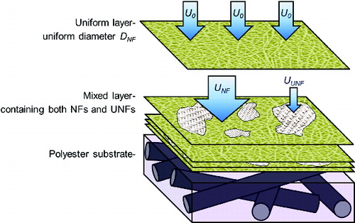
We introduce a layered multiple zone model () to analyze the performance of our electrospun filter media. The model consists of multiple layers of NFs and UNFs on top of the polyester substrate with fiber size D sub = 17 μm. The uniform layers are composed of only NFs and they are assumed to possess a uniform diameter D NF. The mixed layers are composed of both zones of NFs and nanonet structures of UNFs. We assume a uniform diameter D UNF ∼20 nm in each of the UNF medium. The total number of uniform and mixed layers is N and the probability for any of these layers to be a mixed layer is designated as the mixing factor q. The mean coverage factor A averaged over all the mixed layers indicates the area fraction covered by the UNFs. Such a layered multiple zone model reflects the characteristics of our media as can be seen from the SEM images in the Result and Discussion section. At the same time, the model is an idealized simplification ignoring the crossing and tangling fibers and local non-uniformities, similar to the fan model (Kirsch and Stechkina Citation1978) and layered nanofiber and substrate model (Wang et al. Citation2008a,Citationb). The model greatly facilitates analyses of both the pressure drop and filtration efficiency under the hypothesis that the effects due to different layers can be independent from each other. A list of principal symbols used in this model is summarized in .
TABLE 1 Symbols for parameters used in the layered multiple zone model
FIG. 1. A schematic for the layered multiple zone model composed of both NFs and UNFs on top of the polyester substrate.
Pressure Drop
The pressure drop of an electrospun medium was due to the substrate, the uniform layers, and the mixed layers. For a sample with N layers of electrospun fibers and the mixing factor q, the total pressure drop can be expressed as
[1] where Δpsub, Δpuni, and Δpmix are the pressure drop values of the substrate, a uniform layer, and a mixed layer, respectively. Since the fiber sizes in the substrate and uniform layers are Dsub = 17 μm and DNF ∼ 100 nm, respectively, Δpsub and Δpuni can be computed by applying an analytical expression in the slip flow regime (Wang et al. Citation2008a). It is based on the Kuwabara flow with the slip correction (Brown Citation1993):
[2] where μ is the air viscosity; αsub is the solidity of the substrate; t is the thickness of the substrate; U0 is the face velocity; and Kn is the Knudsen number, defined as the ratio between the mean-free-path of air and the fiber radius. For a uniform layer, the equation takes the form
[3] where αuni is the effective solidity of the uniform layer. Since Δpuni is the pressure drop caused by one uniform layer, the thickness of the layer is equivalent to the NF diameter DNF.
Computation of the pressure drop of a mixed layer, Δpmix, is relatively complicated. The flow velocities passing through the NF zones and UNF zones are different. More air would turn to pass through the NF zones, due to the higher air resistance caused by the much smaller fiber diameter in the UNF zones. Under the assumption of independence between layers, the air distribution eventually should strike a balance between the pressure drops in the NF and UNF zones, at the same time the total air flow rates passing through these two zones should add up to the flow rate through the whole filter medium. The face velocity through the NF zones, UNF, and that for the UNF zones, UUNF, can be estimated according to EquationEquations (4)[4] and Equation(5)
[5]
[4]
[5] ΔpNF follows EquationEquation (3)
[3] with the velocity being UNF and the solidity being αNF. The very small fiber diameter for UNFs renders the Kn number well above the unity and turns the flow to the transition regime. Pich (Citation1971) developed EquationEquation (6)
[6] to calculate the pressure drop in the transition regime approaching free molecular flow behaviors.
[6] where p is the characteristic ambient pressure; αUNF is the effective solidity of the UNF zones; and Δpc is the theoretical pressure drop computed using continuous flow regime equation. Here, an equation given by Davies (Citation1973) was chosen, which is known for satisfactory agreement for micrometer fibers
[7]
Single-Fiber Efficiency for NFs
Similarly to computing pressure drop, estimate of the penetration though NFs and UNFs also requires different equations corresponding to the differences in the fiber diameter and flow regime. For the penetrations of the substrate Psub, uniform layers Puni, and the single layer penetration through the NF zones in the mixed layers PNF, the single-fiber filtration theory is applied. For that of the UNF zones in the mixed layers, new models are developed and explained below.
The classical single-fiber filtration theory has been employed in the literature and showed good agreement with experiments with the fiber diameter down to 0.1 μm (Wang et al. Citation2008a,Citationb). In this theory, the single fiber efficiency, ϵT, is considered to be the sum-up efficiency of particle deposition mechanisms including diffusion, interception, impaction, and gravitation (Hinds Citation1999). Wang et al. (Citation2007) provided an empirical expression for the efficiency due to diffusion ϵD for nanoparticle filtration:
[8] where Pe is the Peclet number and defined as
where D is the diffusion coefficient, k is the Boltzmann constant, T is the temperature, Cc is the slip correction factor, and Df is the fiber diameter, representing Dsub or DNF for the substrate or nanofibers, respectively. The efficiency due to interception ϵR can be expressed (Pich Citation1966) as
[9] where R is the ratio between the particle and fiber diameters. Other mechanical means of filtration, such as inertial impaction or gravitational settling, are negligible in our study, since the test particle range is only up to 450 nm, whereas the enhanced collection due to interception of the diffusing particles might play a role, especially when the particle size is near the size of minimum efficiency (Hinds Citation1999):
[10] where
is the Kuwabara hydrodynamic factor.
The total filtration efficiency ϵT caused by one single fiber shall be shown as EquationEquation (11a)[11a] and can be simplified as EquationEquation (11b)
[11b] (Hinds Citation1999)
[11a]
[11b]
The penetration of the whole filter media, P, then can be expressed as
[12]
It is worth to mention that for computing one layer penetration of NF zones, PNF, the fiber diameter DNF should be applied as the thickness t in EquationEquation (12)[12] , and the face velocity is UNF instead of U0.
Interception Mechanism for the UNF Zones
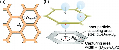
The UNF diameter (∼20 nm) is smaller than the majority of the test particles (15–450 nm). Thus, the assumption in the single-fiber theory for interception, that the particles follow the curved gas streamlines around the fiber, is no longer reasonable. In addition, the large particles captured by the UNF net structure may deposit on multiple UNFs. Therefore, the interception model for fibrous filters in the single-fiber theory is not suitable for the UNF zones and a new model is needed. We assume that the particle trajectories are not disturbed by the very small UNFs, i.e., they fly perpendicular to the UNF layer. The same type of assumption was used by Brown (Citation1993) for particles with large inertia. Based on the morphological studies of electrospun nanonets (Wang et al. Citation2013), we simulate the structure of UNF zones by a layer of hexagonal nets of a uniform pore size (defined as the distance between the centers of two parallel UNFs) of Do, with each edge being one UNF with the diameter DUNF, as shown in . This structure has the advantage of the minimal material required for architectures and the fulfilment of the 120° joint of Steiner geometry.
FIG. 2. A schematic for (a) a unit cell of hexagonal UNF net structure and (b) the corresponding interception mechanism.
The volume of this unit Vo can be represented by the thickness of one layer medium, which is equal to DUNF, multiplied by the unit area Ao:
[13]
As the solidity is defined to be the volume fraction of the fibers in the medium, the solidity of UNF zones αUNF should fulfil the following equation in this model:
[14]
Therefore, the pore size Do can be expressed by the UNF diameter DUNF and the solidity αUNF
[15]
As shown in , particles with the diameter Dp can escape through the UNF zone only when their centers of mass are located no less than Dp/2 from the nearest fiber at the moment crossing the medium, i.e., in the inner hexagonal area AE, which has a size of (Do − DUNF − Dp). Provided that particles are uniformly distributed in the air before reaching the UNF medium, the efficiency due to interception is the area fraction not covered by AE:
[16]
The above derivation for interception is similar to that for a capillary pore filter (Spurny et al. Citation1969; Heidam Citation1980; Chen et al. Citation2013a,Citationb). It should be noted that the sieve effect renders total retention of particles when the sum of the particle and UNF diameters is larger than the pore size D0
[17]
Since the interference by the neighboring fibers is not negligible, the expression of single fiber deposition efficiency for diffusion with the Kuwabara hydrodynamic factor obtained by Pich (Citation1965) is used:
[18]
Hence, the total penetration of a layer of UNF medium can be written as
[19]
Once we have the penetrations of all the components in the layered medium, the total penetration of a testing filter medium is the product of the three component filter media:
[20] where
is the penetration times to the corresponding fraction of air passing though different zones, to the power of the number of mixed layers. The parameters α, N, q, and A are obtained by the best match between the model values of EquationEquations (1)
[1] and Equation(20)
[20] and the experimental data.
RESULTS AND DISCUSSION
Fabrication of Nylon-6 UNF Media
Fiber Morphology
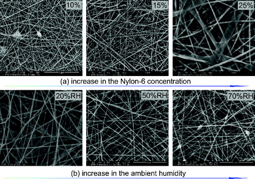
Various operating parameters are investigated, and we observe similar effects on the fiber morphology by the polymer solution concentration and ambient humidity as in the literature (Ding et al. Citation2006; Costolo et al. Citation2008). Under the standard operating conditions (voltage = 20 kV, collecting distance 15 cm), the UNF structure exists in the electrospun samples when the concentration is higher than 15% (). shows that homogeneous NFs or some beaded structures are obtained when RH is 50% or higher. A continuous increase in the UNF covering fraction appears when the ambient humidity decreases from 50% to 10% RH. In all cases, the ribbon-like fibers are accompanied by the occurrence of UNFs.
FIG. 3. SEM images of electrospun media obtained from the Nylon-6 solutions with different (a) concentrations and (b) relative humidity (RH).
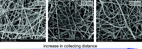
When the collecting distance, defined as the length from the needle tip to the collector, is short, UNFs do not fully expand (Ding et al. Citation2006) so that the net structure is compact but the total covering area is limited (). But prolonging the collecting distance does not always benefit the UNF covering ratio. Our study shows that the UNF density drops significantly and fewer layers of the fibers are obtained when the collecting distance is extended to 25 cm. Meanwhile, a large amount of fine fibers deposit on the chamber bottom, indicating those could be the NFs or UNFs which lose charges in the air, resulting in losing driving force toward the collector. In particular, the UNF structure is most readily obtained at the collecting distance of 10 cm.
FIG. 4. SEM images of the electrospun media collected with different collecting distances. The polymer solution concentration was 20% for all the samples.
Comparing to the other parameters, the effect on the UNF formation caused by aging of the polymer solution is scarcely mentioned in the literature. shows the SEM images of samples produced from 10%, 20%, and 25% Nylon-6 solutions, either when they are freshly prepared or 2-month old. The disappearance of ribbon-like fibers and UNFs are clearly noticeable for the samples from the aged solutions. These trends can be attributed to the Nylon-6 degradation by formic acid during long standing periods. It is reported that Nylon-6 could be attacked by formic acid to become a series of short-chain oligomers with sufficient monomers in ionic form –C(= O)NH2+– (Schaefgen and Trivisonno Citation1951; Nam et al. Citation2011). The shortening of Nylon molecular chains decreases the solution viscosity; meanwhile an increase in the number of ions may enhance its conductivity. Thus, the aged solutions lead to a decrease in the NF diameter and more and larger beads, in line with the literature on electrospun macrostructures (Nam et al. Citation2011). For the UNFs, solutions with low viscosities are unfavorable for forming ribbon-like fibers, which leads to lower UNF coverage fractions.
FIG. 5. SEM images of electrospun media produced from freshly made or aged polymer solutions in various concentrations.
In previous studies of both NF (Costolo et al. Citation2008) and UNF (Ding et al. Citation2006) morphologies, the voltage was a key factor to achieve various fiber morphologies. This factor, however, does not influence the fiber structure significantly under our standard conditions with the applied voltage changed between +15 kV and +30 kV. The density of the UNFs stays low and the mean NF diameter is kept around 80 nm and 110 nm, for 10% and 20% solutions, respectively (SEM images not shown). It seems like the high operating relative humidity, around 40% RH, in our standard electrospinning procedure restrains the influence of applied voltage and results in the divergence between our results and the literature.
Formation Mechanisms
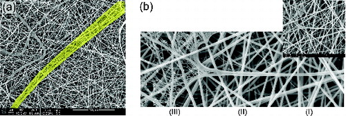
Based on the literature and our discoveries, herein we propose that the formation of UNFs can be a result of stretching ribbon-like fibers by electric forces and the following phase separation leading to net-like structures. It has been described in details by Tsou et al. (Citation2011) how a ribbon-like fiber can be formed by making a solid skin mask at the jet surface by rapid evaporation. In cases where the skin mask is strong enough to withstand the external stresses and the electric repulsion force, the fiber stays as a whole, dries slowly to become the ribbon-like shape. These authors suggested that UNF net structure may appear when cracks on the skin are formed by the electric stresses so the subsidiary jets emerge by squeezing out the solution through the cracks. In contrast to the “squeezed out” mechanism, we propose that the skin-masked jet may be stretched by the electric force. The remaining solution within the jet core is exposed to the air via the cracks on the skin and is expand to be a thin film, then undergoes a spinodal phase separation, which turns the film into separated solvent-rich and polymer-rich regions. In the meantime, favorable ambient conditions may allow the solvent in the expanded film to evaporate quickly, thus keeping the phase separation in the very early stage before coarsening, in which the dispersed solvent-rich and polymer-rich regions may be driven by interfacial tension and re-combine to become a continuous domain. The solvent-rich regions are ultimately transformed into pores while the polymer-rich regions stay as the interconnected net structure. Similar process was applied on the surface of poly(methyl methacrylate) (PMMA) membranes to obtain the lacy surface structure (Tsai and Torkelson Citation1990). We have found examples in our samples for corroboration of our proposed formation process. shows a partially split ribbon-like fiber, with its inner part displaying the pattern of UNF net. illustrates a cylindrical nanofiber (part I), which is stretched in the longitudinal direction into a framed ribbon (part II); finally the flattened ribbon ruptures to form a net structure with UNFs (part III).
FIG. 6. SEM images that illustrate the formation mechanism: (a) a partially split ribbon-like fiber and (b) a fiber partially split in the longitudinal direction; the panel on the top right corner is a zoomed-out view of the same fiber.
Based on our proposed mechanism, it is clear that skin masks with suitable strength and the possibility for the polymer jets undergoing a rapid evaporation should be favorable for obtaining the UNF structure. The influence by the polymer concentration is obvious, since there is a limit of the amount of polymeric molecules to form the skin masks with the appropriate strength. The ambient relative humidity, as proposed by Ding et al. (Citation2006), controls the evaporating speed of the solvent within the jet. Provided that the UNF structure is a consequence of the very early stage of phase separation dominated by a spinodal decomposition process (Tsai and Torkelson Citation1990; Ding et al. Citation2006), a rapid evaporation on the stretched jet surface is required to achieve the polymer solidification right after the spinodal decomposition. The water molecules in the ambient tend to be taken up by the formic acid solution during both the solution preparation and electrospinning processes, due to the lower vapor pressure of water in the presence of formic acid (Xu et al. Citation2003). The high ambient RH% shall hinder evaporation of the absorbed water molecules, in turn the existence of water molecules slows the evaporation rate of formic acid according to Henry's Law. The decelerated jet solidification process provides enough time for coalescence, instead of fixing the structure in the early stage of phase separation in order to form the UNF structure. In comparison with the suggested UNF formation mechanism of charged droplets (Ding et al. Citation2006), the strength of applied voltage has less inference in our suggested UNF formation mechanism because UNFs are not formed by the charged droplets that are produced by the break-up of a jet due to the electrical-field-induced instability. Briefly, the relatively high RH value is the dominant parameter in our experiments, performed under the standard conditions with the RH value around 40%, so that the effect of the electrical voltage is less pronounced.
Our proposed mechanism indicates that the UNFs are formed by splitting NFs, thus the polymeric material should conserve, i.e., the volume of fibers is a constant in the NF and UNF zones in a unit area of a mixed layer. If we use DNF and DUNF for the layer thicknesses in the NF and UNF zones, respectively, the solidity of the UNF nets αUNF can be related to the solidity of the NFs, i.e., the overall efficient solidity, by the following relationship:
[21]
EquationEquation (21)[21] is implemented in the modeling for simulating the filtration performance of each filter sample.
Analysis for the Performance of Electrospun UNF Media
A set of electrospun media were fully characterized for their NF and UNF diameters, solidities, number of layers, and UNF coverage fraction, together with their pressure drop and filtration efficiency. These values are shown in .
TABLE 2 The structural parameters for the filter media and the corresponding operating parameters for their production and filtration tests
Filtration Tests at Different Face Velocities
Samples I, II, and III are electrospun filters produced from the 20 wt% Nylon-6 solution under the standard conditions, although they are made by different electrospinning runs and test under different filtration face velocities. shows the modeled curves of 5, 10, and 15 cm/s while the same estimated values, such as the effective solidity αNF, number of layers N, and UNF overall density, as the product of mixing factor q and covering fraction A, are applied (). The experimental penetration increases with the face velocity increasing from 5 to 15 cm/s, as expected. The curves show general agreement with the respective experimental results while the estimated pressure drops have a discrepancy less than 11% from the experimental values. The modeled curves are close to each other for particles bigger than 100 nm, since the aerosol velocity affects the filtration efficiency of diffusion much more than that of interception (Hung and Leung Citation2011). The most penetrating particle size (MPPS) decreases with the increase of face velocity mildly. It is also worth to mention that the high air resistance of the UNFs leads to extremely asymmetrical air flow through the samples. Even though the UNFs cover over 84% of the area of a mixed layer, the volume of air passing through the UNF zones is only 1/6 of the total air volume. In addition, the 13.1% of UNF overall density introduces more than 64% of the pressure drop, comparing to the calculated Δptotal with non-UNF structure.
FIG. 7. Modeled and experimental data of the penetration tests for Samples I, II, and III.
Filtration Tests for Different Electrospun Media
The filtration performances of samples produced from various Nylon-6 concentrations are displayed in . With 10 min electrospinning of 10% solution (Sample V), the filtration efficiency is significantly improved from the bare substrate (Sample IV). The nanofiber medium provides a smaller MPPS and higher filtration efficiency than the substrate as expected (Wang et al. Citation2008a,Citationb). The MPPS is around 70 nm and the corresponding penetration is about 27% for Sample V, in contrast, the MPPS is around 400 nm and the corresponding penetration is about 99% for Sample IV. However, the improved efficiency comes with the cost of high pressure drop. The pressure drop of Sample V is 81 Pa, 27 times of that of Sample IV. For samples made out of the 20% polymer solution (Samples VI, VII), the pressure drops are doubled or increased even more, due to the increase in the solidity and mixing factor ().
FIG. 8. Modeled and experimental data of the penetration tests for Samples IV, V, VI, and VII.
The effects of the collecting distance can be seen by comparing Samples VI and VII. shows that Sample VII has larger NFs, higher α, and fewer layers of fibers than Sample VI. Moreover, the effective UNF covering fraction A of Sample VII is 78%, slightly less than 85% for Sample VI. Based on EquationEquation (15)[15] , the derived pore sizes of the UNF nets are 810 nm and 357 nm for Samples VI and VII, respectively. All the phenomena can be explained by our purposed mechanism. The liquid jets have less time for splitting and elongation before deposition with a short collecting distance. As a result, the same amount of polymer material is sprayed to a narrower area on the collector, resulting in thicker and denser layers of fibers. Due to the same reason, the ribbon-like fibers, responsible for UNF formation are less extended. It results in that the UNF structures in Sample VII are less uniformly distributed in the medium but have a higher local density, as found in the SEM images. The estimated parameters suggest that UUNF is 1.19 cm/s in Sample VII, around 42% less than that in Sample VI, which is due to the lower overall UNF density. Consistent with the reduced number of layer of Sample VII, the MPPS drops from 94 nm to 58 nm when the collecting distance decreases from 15 cm to 10 cm, while the corresponding penetration stays around 0.059 for both samples. Nanoparticles less than the crossover point of the two curves of 80 nm shall have higher penetration in Sample VII than Sample VI.
Nevertheless, discrepancies between the modeling results and experimental data can still be noticed, especially for particles smaller than 50 nm. Similar performance has been found in NF filtration modeling by Wang et al. (2008a) and considered to be a result of non-uniformity in the filter micro-structure. We propose that the UNFs are formed by splitting the ribbon-like fibers, which causes inhomogeneity among the typical cylindrical NFs. As can be seen in the SEM images (), the fiber diameter distribution is wider in the UNF present samples. And it still holds even if the UNF structure is excluded. In addition, UNF nets in the filter samples do not have uniform pore size as assumed. Some UNF nets may even be partially broken due to the strong electrical stretching force, and lead to zones of higher local porosity. These variations can result in a higher penetration than the computed curves. For Sample VII, which has less time for stretching before deposition, there is less possibility for the UNF nets to be broken. As a result, a less discrepancy between the modeling curve and experimental data for particles smaller than 50 nm can be seem in . Furthermore, we simplified the model with the assumption that the filter media consist of parallel segregated layers and the efficiencies by each layer are independent. However, the filters are actually composed of fibers with random orientations. No clear gaps exist between layers. The airborne particle motion right in front of a fiber is dependent on the preceding flow path, with the possibility of switching between slip flow regime and transition regime. In any event, with a number structural parameters obtained by matching the modeling and experimental results, the fact that satisfactory agreement is obtained for multiple media under different filtration test conditions, demonstrating that the model gives sound description for the media structure and underlining physics.
The filter performance may be evaluated by different criteria due to various filtration needs. In the set of Samples V–VII, we have filter media with increasing UNF overall densities with a moderate increase of the solidities. When the filter media are evaluated by their quality factor QF, defined as QF = −ln(P)/Δp (Wang et al. Citation2008a,Citationb), the samples with higher UNF overall densities have lower QF in the whole particle size range below 400 nm (). The quality factor QF does not improve from Sample V to VII since the solidity gradually increases. That results in a significant growth of Δp, which outweighs the increase of the filtration efficiency. The simulated quality factors of three mono-structural filters of UNFs (20 nm), NFs (100 nm), and microfibers of 2 μm in diameter are shown in the same figure for comparison. It is clearly shown that the experimentally measured QF values of the composite filters generally lie between the UNF and NF curves, and have flatter curves than the mono-structural filters, due to the bimodal distribution of the filter diameter. The mono-structural filters are simulated with the same solidity of 0.003. The results indicate that UNFs can lead to improvement of the quality factor comparing to the NF filter at certain face velocity and solidity values, however, such mono-structural UNFs have not be achieved experimentally.
FIG. 9. Quality factor QF for Samples V–VII and three simulated mono-structure Nylon-6 fibers in 2 μm (Microfiber), 100 nm (NF), and 20 nm (UNF) filters. The velocity is 10 cm/s for all tests.
It is of interest to compare the filtration performance of a fixed basis weight for different structure of filters, especially when the high filtration efficiency is required with limited filter material or space. The specific filtration performance index Is can be defined as
[22] where BS is the basis weight, for which the unit of mg/m2 in chosen this study. In , the Is for Nylon-6 is calculated for Samples V–VII as well as the three aforementioned mono-structural filters. It can be noticed that when the mono-structural fiber size reduces from 2 μm to 20 nm, the Is value increases drastically. The lowest Is for 2 μm, 100 nm, and 20 nm filters are 3.17 × 10⁻⁵, 9.41 × 10⁻³, and 0.647, respectively. This can be understood as the same amount of material is split into finer fibers and the exposed surface area and thus the sites to capture particles increase. All of the electrospun Samples V–VII have better Is than the mono-structural NF curve. However, the increase in weight of filter media outweighs the increase in filtration performance when UNF density increases for this set of filter samples with the caveat that the solidity also varies. For now, the uniform UNF medium is still not achieved without the appearance of NFs in actual operation. However, the calculation indicates the best performance that UNF structure can perform. Consequently, UNFs is a potentially good candidate for air filtration once the UNF uniformity and solidity can be further controlled.
FIG. 10. The computed specific filtration performance index Is for Samples V–VII and the simulated mono-structural Nylon-6 fibers in 2 μm (Microfiber), 100 nm (NF), and 20 nm (UNF) filters. The unit area of the assumed filters is 1.0 mg/m2.
CONCLUSIONS
We investigated production of Nylon-6 electrospun media, including the influence of solution properties and several process parameters on the UNF structure, a net-like 2D structure with the fiber size around 20 nm. Based on the morphology of the fibers, we propose that formation of the UNF structure can be a result of splitting ribbon-like fibers by the external electric force, followed by the rapid phase separation of the splitting film. The formation is strongly dependent on the polymer solution concentration and age, the collecting distance, and ambient relative humidity.
The nanoparticle penetration was experimentally evaluated using monodisperse NaCl aerosols of different sizes. The results show that both the filtration efficiency and pressure drop increase as the density of UNFs increases. A layered multiple zone model with analytical expressions suitable for the transition flow regime and the net-like UNF structure is developed to simulate the pressure drop and filtration efficiency for the filter media with UNFs. The simulation results are in good agreement with experiments under different filtration test conditions. The model is then used to estimate the solidity and UNF fraction for samples produced from Nylon-6 solutions under different operating conditions. The calculated UNF fraction qualitatively agrees with that observed from the SEM images. The filtration performance of the electrospun media is evaluated in terms of the quality factor and the specific filtration performance index based on a fixed basic weight. Our results show that the UNF structure can be advantageous in air filtration, especially for applications where high efficiency and limited filter material or space are desired.
FUNDING
The authors thank the support of members of the Center for Filtration Research: 3M Corporation, BASF Corporation, Boeing Commercial Airplanes, Cummins Filtration Inc., Donaldson Company, Inc., Entegris, Inc., H.B. Fuller Company, Hollingsworth & Vose Company, MANN+HUMMEL GMBH, MSP Corporation, Samsung Electronics Co., Ltd., Shigematsu Works Co., Ltd., TSI Inc., and W. L. Gore & Associates, Inc., and the affiliate member National Institute for Occupational Safety and Health (NIOSH).
Related Research Data
REFERENCES
- Brown, R. C. (1993). Air Filtration: An Integrated Approach to the Theory and Applications of Fibrous Filters. Pergamon Press, London.
- Chen, S.-C., Wang, J., Fissan, H., and Pui, D. Y. H. (2013a). Use of Nuclepore filters for Ambient and Workplace Nanoparticle Exposure Assessment- Spherical Particles. Atmos. Environ., 77:385–393.
- Chen, S.-C., Wang, J., Fissan, F., and Pui, D. Y. H. (2013b). Exposure Assessment of Nanosized Engineered Agglomerates and Aggregates Using Nuclepore Filter. J. Nanopart. Res., 15:1955.
- Costolo, M. A., Lennhoff, J. D., Pawle, R., Rietman, E. A., and Stevens, A. E. (2008). A Nonlinear System Model for Electrospinning Sub-100 nm Polyacrylonitrile fibres. Nanotechnology, 19:035707.
- Davies, C. N. (1973). Air Filtration. Academic Press, London.
- Ding, B., Li, C. R., Miyauchi, Y., Kuwaki, O., and Shiratori, S. (2006). Formation of Novel 2D Polymer Nanowebs via Electrospinning. Nanotechnology, 17:3685–3691.
- Faccini, M., Amantia, D., Vázquez-Campos, S., Vaquero, C., López de Ipiña, J. M., and Aubouy, L. (2011). Nanofiber-Based Filters as Novel Barrier Systems for Nanomaterial Exposure Scenarios. J. Phys. Conf. Ser., 304:012067.
- Gibson, P., Schreuder-Gibson, H., and Rivin, D. (2001). Transport Properties of Porous Membranes Based on Electrospun Nanofibers. Colloids Surf. A Physicochem. Eng. Aspects., 187–188:469–481.
- Heidam, N. Z. (1980). Review: Aerosol Fractionation by Sequential Filtration with Nucleopore Filters. Atmos. Environ., 15:891–904.
- Hinds, W. C. (1999). Aerosol Technology: Properties, Behavior, and Measurement of Airborne Particles. Wiley-Interscience, New York.
- Hung, C.-H., and Leung, W. W.-F. (2011). Filtration of Nano-Aerosol Using Nanofiber Filter Under Low Peclet Number and Transitional Flow Regime. Sep. Purif. Technol., 79:34–42.
- Kim, S. C., Harrington, M. S., and Pui, D. Y. H. (2007). Experimental Study of Nanoparticles Penetration Through Commercial Filter Media. J. Nanopart. Res., 9:117–125.
- Kirsch, A. A., and Stechkina, I. B. (1978). The Theory of Aerosol Filtration with Fibrous Filters, Section 4, in Fundamentals of Aerosol Science, D. T. Shaw, ed., Wiley-Interscience, New York, pp. 170–252.
- Kuwabara, S. (1959). The Forces Experienced by Randomly Distributed Parallel Circular Cylinders or Spheres in a Viscous Flow at Small Reynolds Numbers. J. Phys. Soc. Jpn., 14:527–532.
- Lee, S., and Obendorf, S. K. (2006). Developing Protective Textile Materials as Barriers to Liquid Penetration Using Melt-Electrospinning. J. Appl. Polym. Sci., 102:3430–3437.
- Lu, P., and Ding, B. (2008). Applications of Electrospun Fibers. Recent Pat. Nanotechnol., 2:169–182.
- Nam, K.-T., Pant, H. R., Jeong, J., Pant, B., Kim, B., and Kim, H.-Y. (2011). Solvent Degradation of Nylon-6 and its Effect on Fiber Morphology of Electrospun Mats. Polym. Degrad. Stability, 96:1984–1988.
- Pich, J. (1971). Pressure Characteristics of Fibrous Aerosol Filters. J. Colloid Interface Sci., 37:912–917.
- Pich, J. (1965). The Filtration Theory of Highly Dispersed Aerosols. Staub Reinalt. Luft., 5:16–23.
- Pich, J. (1966). The Effectiveness of the Barrier Effect in Fiber Filters at Small Knudsen Numbers. Staub Reinalt. Luft., 26:1–4.
- Podgorski, A. (2009). Estimation of the Upper Limit of Aerosol Nanoparticles Penetration Through Inhomogeneous Fibrous Filters. J. Nanopart. Res., 11:197–207.
- Podgorski, A., Maißer, A., Szymanski, W. W., Jackiewicz, A., and Gradon, L. (2011). Penetration of Monodisperse, Singly-Charged Nanoparticles Through Polydisperse Fibrous Filters. Aerosol Sci. Technol., 45:215–233.
- Schaefgen, J. R., and Trivisonno, C. F. (1951). Polyelectrolyte Behavior of Polyamides: Viscosities of Solutions of Linear Polyamides in Formic Acid and Sulfuric Acid. J. Am. Chem. Soc., 73:4580–4585.
- Schreuder-Gibson, H., Gibson, P., Senecal, K., Sennett, M., Walker, J., et al. (2002). Protective Textile Materials Based on Electrospun Nanofibers. J. Adv. Mater., 34:44–55.
- Spurny, K., Lodge, J. P., Frank, E. R., and Sheesley, D. C. (1969). Aerosol Filtration by Means of Nuclepore Filters: Structural and Filtration Properties. Environ. Sci. Technol., 3:453–464.
- Tsai, F.-J., and Torkelson, J. M. (1990). Roles of Phase Separation Mechanism and Coarsening in the Formation of Poly(methacrylate) Asymmetric Membranes. Macromolecules, 23:775–784.
- Tsou, S.-Y., Lin, H.-S., and Wang, C. (2011). Studies on the Electrospun Nylon 6 Nanofibers from Polyelectrolyte Solutions: 1. Effects of Solution Concentration and Temperature. Polymer, 52:3127–3136.
- Wang, J., Chen, D. R., and Pui, D. Y. H. (2007). Modeling of Filtration Efficiency of Nanoparticles in Standard Filter Media. J. Nanopart. Res., 9:109–115.
- Wang, J., Kim, S. C., and Pui, D. Y. H. (2008a). Investigation of the Figure of Merit for Filters with a Single Nanofiber Layer on a Substrate. J. Aerosol Sci., 39:323–334.
- Wang, J., Kim, S. C., and Pui, D. Y. H. (2008b). Figure of Merit of Composite Filters with Micrometer and Nanometer Fibers. Aerosol Sci. Technol., 42:722–728.
- Wang, J., and Tronville, P. (2014). Toward Standardized Test Methods to Determine the Effectiveness of Filtration Media Against Airborne Nanoparticles. J. Nanopart. Res. 16:2417, DOI: 10.1007/s11051-014-2417-z.
- Wang, N., Wang, X., Ding, B., Yu, J., and Sun, G. (2012). Tunable Fabrication of Three-Dimensional Polyamide-66 Nano-Fiber/Nets for High Efficiency Fine Particulate Filtration. J. Mater. Chem., 22:1445–1452.
- Wang, X., Ding, B., Sun, G., Wang, M., and Yu, J. (2013). Electro-Spinning/Netting: A Strategy for the Fabrication of Three-Dimensional Polymer Nano-Fiber/Nets. Prog. Mater. Sci., 58:1173–1243.
- Xu, Q., DeWitte, M., and Sloan, J. J. (2003). The Effect of Formic Acid on the Deliquescence of Model Sea-Salt Aerosol Particles. Atmos. Environ., 37:911–919.
- Yao, F., Xu, L., Lin, B., and Fu, G.-D. (2010). Preparation and Applications of Functional Nanofibers Based on the Combination of Electrospinning, Controlled Radical Polymerization and ‘Click Chemistry.’ Nanoscale, 2:1348–1357.