 ?Mathematical formulae have been encoded as MathML and are displayed in this HTML version using MathJax in order to improve their display. Uncheck the box to turn MathJax off. This feature requires Javascript. Click on a formula to zoom.
Abstract
The deposition of micron and submicron particles in metallic, ceramic, or synthetic open-pored foams is a special field of aerosol filtration in porous media. This is due to the more complicated pore structure than, for example, fibrous filter media. Therefore, the measurement as well as the simulation of aerosol filtration in open-pored foams involves certain custom-built techniques.
The filter efficiency for micron and submicron particles can be measured by differential electrical mobility analyser systems (DEMAS) or optical particle counters (OPC). Empirical formulas are available in literature for open-pored polyurethane foams to determine their aerosol filtration efficiency and pressure drop. An additional method for characterization is direct numerical simulation (DNS) by means of a three-dimensional (3D) model of the pore structure. These models can be obtained either by tomography or by mathematical generation.
In this work, the filter efficiency of an open-pored nickel foam with a cell diameter of 450 μm is determined by the methods previously mentioned. The experimental results are in good agreement with the results of the 3D simulation and a semi-empirical approach for polyurethane foams is adapted for a nickel foam.
Copyright 2015 American Association for Aerosol Research
1. INTRODUCTION
Characteristics for open-pored foams are a high porosity resulting in a low pressure drop and mechanical strength. In addition, they can provide thermal durability and chemical resistance when customized coatings are applied to the polyurethane skeletal structure (Kim and Lee Citation2014).
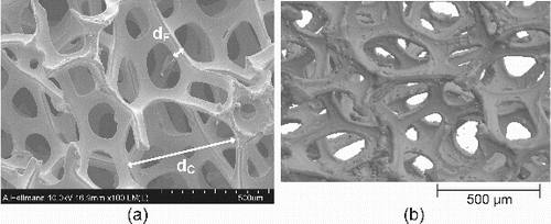
The geometry of these open-pored foams is usually specified by cell and link diameter. The SEM micrograph in a shows the inner structure of the nickel foam investigated in this work. In the picture the link diameter dL and the cell diameter dc are marked. Figure 1b shows a microtomography of the same foam.
FIG. 1. Scanning electron microscope (SEM) picture of real structure (a) and a tomography (b) of the inspected open-pored nickel foam.
Because of these functional and structural attributes, open-pored foams are highly porous and permeable materials, which are suitable for a wide range of technical applications. In particular they can be utilized for air filtration or personal air sampling (Aitken et al. Citation1993; Vincent et al. Citation1993; Möhlmann et al. Citation2002).
Semi-empirical formulas for the particle penetration through open-pored foams have been introduced by Gibson and Vincent (Citation1981), Vincent et al. (Citation1993), Kenny et al. (Citation2001) and Clark et al. (Citation2009). They are based on each other and cover particle deposition by impaction, gravitational settling, and diffusion. In case of a polyurethane foam, the works of these authors show a good agreement between experimental data and the results calculated with the semi-empirical formulas.
In this work, particle deposition in a nickel foam is investigated experimentally. Based on these results, the formulas for the nickel foam mentioned above are adapted. The characteristic dimensions of this foam are given in .
Table 1 Material properties of the utilized nickel foam
In addition, we carried out a 3D simulation of the fluid permeation and particle deposition in the nickel foam. For the simulations the in-house developed software DNSlab is used (Schmidt Citation2011). With this software, a direct numerical simulation of the flow field and derived from this, particle deposition inside the foam is possible, if a 3D model of the pore structure is given. This model can be achieved either by tomography or be generated by an algorithm based on essential structure parameters (Redenbach et al. Citation2011; Schmidt and Becker Citation2013). In the presented work, tomographical open-pored foam models as well as models generated by a novel algorithm are used. The simulation results are compared to both, the adapted and the original semi-empirical formulas as well as the experimental results, which have also been conducted by the authors.
2. EXPERIMENTAL SETUP
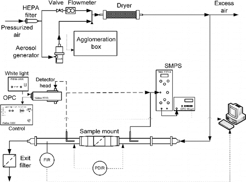
illustrates the setup for filtration efficiency experiments with sodium chloride (NaCl) particles. The aerosol is generated using a Collison nebulizer (TU Kaiserslautern) or an AGK 2000 (Palas Model AGK 2000) combined with an agglomeration box. To generate a defined aerosol distribution, a high efficiency particulate air (HEPA) filter is used to supply the aerosol generator with particle free, compressed air. The generated aerosol is diluted by an air stream which is controlled using a flowmeter. Subsequently, the flow passes a diffusion dryer. The experiments are carried out with a constant face velocity of 0.055 m·s−1. The concentration and particle distribution of the aerosol is measured up- and downstream of the fixed foam material. The foam itself is fitted into a sample mount. During the filter test the pressure drop induced by the foam is recorded.
To characterize the particle distribution in the submicron size range a scanning mobility particle sizer (SMPS, TSI Model No 3934) device is used. Particles larger than 1 μm are detected with an optical particle counter (OPC, Palas Model Welas 3000) on the downstream site of the sample mount (Hellmann et al. 2012).
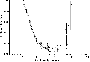
In , the measured filtration efficiency for the investigated nickel foam is shown.
The measured particle size distributions have a mean diameter of about 40 nm (SMPS, 13 nm–835 nm) and roundabout 0.85 μm (OPC, 0.2 μm–10 μm). For particles sizes below 200 nm, the standard deviation is quite low. It increases for particles larger than 200 nm, because the amount of particles decreases. More experiments with higher particle concentrations need to be conducted to reduce the standard deviation of the measured filtration efficiency in this area.
3. EMPIRICAL MODELS
3.1. Particle Deposition
Brown (Citation1980) investigated the aerosol penetrations through porous plastic foams. He measured the charge on a foam using a Faraday ice-pail and it was found to be negligible. Accordingly, influence of electrostatic forces for the particle deposition can be neglected if the foam is uncharged. In this work, the investigated foam is considered uncharged, too. Therefore, the deposition of particles in open-pored foams is described by three characteristic quantities, where the Stokes number St represents the particle deposition by inertia, the parameter NG the gravitational settling and the Peclet number Pe the particle deposition by diffusion[1]
[1]
[2]
[2]
[3]
[3] where
is the density of the particles and
is the particle diameter,
is the velocity of the air through the foam,
is the viscosity of the air,
is the acceleration of gravity,
is the fiber diameter,
is the absolute temperature,
is the Boltzmann constant, and
the Cunningham slip correction (Baron and Willeke Citation2005).
Vincent et al. (Citation1992) investigated the efficiency of the prediction of a model based on the single fiber efficiency.[4]
[4] where
is the thickness of the foam and
the penetration through the foam (filtration efficiency
). The variables a, b, c, and d are determined by non-linear regression to fit the records gained from previous works of other authors as Gibson and Vincent (Citation1981), Wake and Brown (Citation1991). They showed reasonable agreement between the predicted and measured penetrations.
Vincent et al. (Citation1993) introduced an equivalent fiber diameter based on pores per inch
to complete the formula:
[5]
[5]
According to this approach, Kenny et al. (Citation2001) evolved a correlation to gain an equivalent fiber diameter out of the cell diameter with:
[6]
[6] where the equivalent fiber diameter
and the cell diameter
are given in meters.
Clark et al. (Citation2009) calculated their formula with the link diameter evaluated from SEM images of the used foam. This approach is equivalently used in this work.
[7]
[7]
Based on the methodology of Vincent et al. (Citation1993), Clark et al. (Citation2009) added diffusion to complete the deposition effects and adapted the model coefficients to the following equation:[8]
[8]
All units are given in SI units. According to our experimental results, the term for deposition by diffusion (in EquationEquation (8)[8]
[8] ) is adjusted and the model parameters for inertia and settling are taken from Vincent et al. (Citation1992) (EquationEquation (4)
[4]
[4] ), leading to the following equation:
[9]
[9]
With this adapted semi-empirical approach, it is possible to calculate the filtration efficiency of the investigated nickel foam. In the measured and the calculated filtration efficiencies are compared.
FIG. 4. Comparison of the measured and calculated filtration efficiencies for the investigated nickel foam.
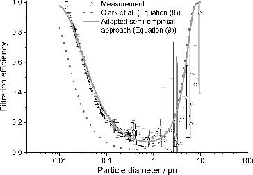
In the particle size range below 200 nm, where diffusion is the dominating deposition effect, the model developed by Clark et al. shows an underestimation of the filtration efficiency compared to our experimental results. This tendency is also shown for a polyurethane foam by Clark et al. (Citation2009) for decreasing link diameter. The lower link diameters investigated by Clark et al. (Citation2009) are comparable to the nickel foam used in this work. Accordingly, the difference in filtration efficiency between the model by Clark et al. (Citation2009) and our experimental results is due to the link diameter of the foam.
3.2. Pressure Drop
Wake and Brown (Citation1991) expressed empirical formulas for pressure drop in porous polyurethane foams with thickness
. The experiments have been carried out for foams from 10 to 100 ppi and face velocities
from 0.01 to 0.2 m/s. The model is written as:
[10]
[10] where A, B, and O (truncated) are depending on
(e.g. 80 ppi: A = 0.42 kg/m3·s1, B = 228 kg·s/m5) (Wake and Brown Citation1991).
If Equations Equation(5)[5]
[5] , Equation(6)
[6]
[6] , and Equation(7)
[7]
[7] are used to compare the pores per inch (ppi) of the foams, the investigated nickel foam is located in the range of 60 to 90 ppi.
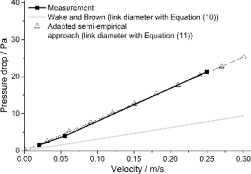
Based on our experimental results, EquationEquation (10)[10]
[10] simplifies to:
[11]
[11] with the new coefficients A = 1.14 kg/m3·s and B = 0 kg·s/m5 for the measured link diameter dL according to .
shows the calculated and measured pressure drops as a function of the face velocity.
In the work of Wake and Brown (Citation1991), the quantity of pores per inch is information given by the manufacturer. Because of the lack of such information for the nickel foam investigated in this work, has to be calculated by Equations Equation(5)
[5]
[5] and Equation(7)
[7]
[7] . EquationEquation (5)
[5]
[5] is developed by Vincent et al. (Citation1993) with foam structures different to Wake and Brown (Citation1991). Hence, our experimental results cannot be predicted with the coefficients given by Wake and Brown (Citation1991) and have to be adapted.
4. 3D Simulation
An additional method for characterization is direct numerical simulation (DNS) by means of a three-dimensional (3D) model of the pore structure. The 3D model can be obtained either by mathematical generation or by tomography. The model generation is done by an algorithm based on essential structure parameters (Redenbach et al. Citation2011; Schmidt and Becker Citation2013). The 3D model is discretized by cubic volume elements denoted as voxels, which are the 3D analogon of a 2D pixel. In both cases a voxel model is obtained (i.e., a 3D pixel image).
Once the 3D pore structure model is prepared, the fluid flow through the porous structure is computed by numerical solution of the steady-state Navier–Stokes equations. The voxel grid is used directly for the discretization. The filter efficiency is obtained by computing the trajectories of particles by the Lagrangian approach. In the following sections, this simulation procedure for the investigated open-pored nickel foam is described in detail.
4.1. Preparation of 3D Pore Structure Models
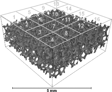
For the generated model as well as for the tomography (Micro-CT, Bruker Model SkyScan 1172) of the nickel foam, a resolution of about 23 μm3 per voxel is used. The tomography shown in is composed of 2444 × 2214 × 853 voxels, which would make the computation of the flow field too resource intensive. Therefore, after removal of blemishes (artifacts) from the tomography procedure, it is subdivided into 16 smaller models for the subsequent computations of air flow and particle trajectories.
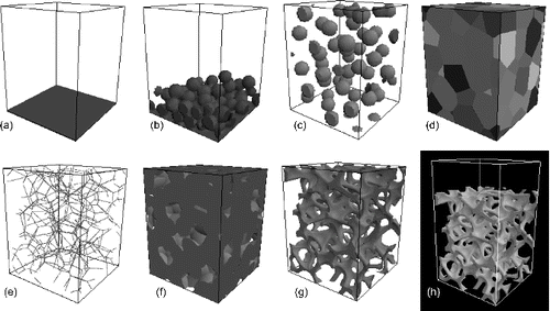
The generation of 3D pore structure models is arranged in such a way that the tomography shown in as well as the parameters displayed in are matched.
The generation is conducted in a sequence of several steps as shown in a–h. It starts with defining the model size and a baseplate (a). An amount of spheres is piled up on the baseplate. The number of spheres is calculated as the target number of cells in the model volume (b). The baseplate is removed and from now on periodic boundary conditions are applied. The spheres are equally distributed in the volume (c). Afterwards the spheres are expanded until they fill the whole free volume (d). The boundaries between 3 or more expanded spheres are marked as the center lines of the links and the expanded spheres are removed (e). By growing the link center lines (f) and afterwards the void phase by certain tunable amounts, the target link diameter and the shape of the link interconnections are adjusted to the real nickel foam exemplar (g). Finally, an inflow area is added (h) for the subsequent simulation of air flow and particle separation.
In order to quantify the dependency of the simulation results on the randomness of the cell distribution in the model, the above sequence of generation steps is conducted repeatedly with different random numbers to generate 16 models.
4.2. Flow Computation
As mentioned above, for a tomography cutout and a generated model, the air flow is computed by direct numerical solution of the Navier–Stokes equations:[12]
[12]
[13]
[13]
[14]
[14] where
is the air velocity,
is the dynamic viscosity of air,
is the density of air,
is the pressure, Ω is the void domain of the microstructure model and ∂Ω is the boundary of Ω, i.e. the structure surface. Inertia is taken into account by the Navier term
.
To solve the Navier–Stokes equations, the artificial compressibility method is used, which is discretized on the staggered grid given by the voxel side faces (velocity) and the voxel centers (pressure) of the model (Schmidt Citation2011; Schmidt and Becker Citation2013). For flow velocities below 0.1 m/s the Reynolds number for the air flow around a single cylindrical link accounts to Re < 1, which implies a flow profile with negligible inertia effect. Therefore the Navier term in EquationEquation (12)[12]
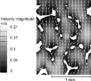
[12] can be neglected. Correspondingly, the Stokes equations are solved. depicts the resulting velocity field (2D cut through the 3D model) for a generated model and a face velocity of 0.055 m/s.
FIG. 8. Flow velocities computed for a generated model of the nickel foam (white) with a face velocity 0.055 m/s.
Common computational fluid dynamics (CFD) software based on polyhedron meshes (e.g., ANSYS Fluent, CD-adapco StarCCM+) is not well suited because the setup of the polyhedron mesh is error-prone for random heterogeneous structures (Skibinski et al. Citation2012).
Apart from the local flow velocities, which are needed to compute the particle trajectories, the pressure drop via the foam is obtained. The pressure drop of multiple foam layers can be computed by multiplying the value for a single layer correspondingly. Also, the pressure drop scales linearly with the flow velocity in the Re < 1 regime.
4.3. Particle Simulation
In the flow field, the particle trajectories are computed by the Lagrangian approach:[15]
[15] where
is the time,
is the particle position,
is the particle velocity,
is the particle-fluid friction coefficient and the term
describes the Brownian motion. illustrates two particle trajectories computed by this method. The movement of the particle with a diameter of 5 nm is dominated by Brownian motion and it performs therefore a random fluctuation around the streamline. The trajectory of the particle with a diameter of 50 μm is in contrast dominated by inertia.
FIG. 9. Trajectories of spherical particles with diameters of 5 nm and 50 μm computed in the flow field shown in Figure 8.
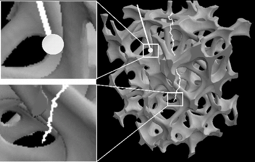
For the computation of the filtration efficiency for a tomography cutout or a generated model, 106 spherical particles with diameters in the range of 0.001 to 100 μm are tracked. The initial positions are generated randomly in the inflow area. As soon as a particle contacts the structure surface it is regarded deposited. The filtration efficiency is then computed as the ratio of deposited particles to the total number of particles. To calculate the filtration efficiency of multiple layers of the nickel foam, an exponential approach is used; the particle concentration decreases exponentially with increasing foam height (Löffler et al. Citation1988; Schmidt Citation2011).
5. RESULTS AND DISCUSSION
5.1. Filtration Efficiency
The simulated filtration efficiencies for tomography cutouts and generated models are shown in . The depicted curves represent the arithmetic mean of the 16 simulations for the tomography cutouts respectively the multiple generated models. For better visualization of the small difference between the two curves, a logarithmic scale for the ordinate is used. The simulations are carried out for a flow velocity of 0.055 m/s. The results for the tomography and the generated model show a very good agreement.
FIG. 10. Simulated filtration efficiencies for 16 mm nickel foam with tomography cutouts and generated models. The face velocity is 0.055 m/s.
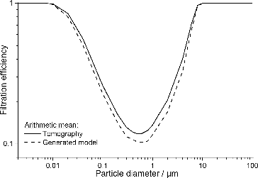
If information about porosity and link diameter is available, the novel algorithm for model generation can reproduce the inner geometrical structure of the investigated foam quite well. Nevertheless the deviation at the most penetrating particle size (MPPS) between 0.6 μm and 0.8 μm, reflects the small geometric differences of the tomography and the generated models. The standard deviation of both curves is about 5% for the whole range of particle sizes.
shows the comparison of the experimental results, the calculated mean filtration efficiency for the generated 3D models and the adapted semi-empirical formula for the nickel foam with 16 mm height. A face velocity of 0.055 m/s is used.
FIG. 11. Comparison of the measured, calculated and simulated filtration efficiencies for the investigated nickel foam.
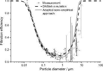
In the submicron regime, the DNSlab simulation and the adapted semi-empirical approach fit the experimental data very well. For particle diameters above 1 μm the standard deviation of the measured filtration efficiency hinders an accurate statement, but the qualitative dependence of filtration efficiency on size is clear. Furthermore, the adapted semi-empirical approach and the 3D simulation do not depart over most of the investigated particle size area.
5.2. Pressure Drop
In , the experimental and simulated results are compared to the pressure drop derived by the semi-empirical formula for face velocities of 0.01 to 0.3 m/s.
FIG. 12. Comparison of the measured, calculated, and simulated pressure drop for the investigated nickel foam.
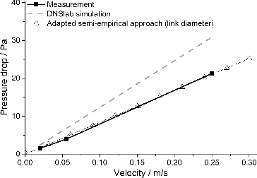
The difference in gradient between the results of the simulation and the experiment can be explained as follows. During a filtration process, fluid flow prefers to stream through areas with high permeability. This results in a pressure drop which is lower than the arithmetic mean of the simulated values for each of the 16 generated models. Simulations with cutouts of a fibrous filter medium were carried out, too. The results show the same tendency. With larger cutouts of fibrous filter media improved results for the simulated pressure drop can be observed. This can also be realized with an open pored foam filter medium, but this modeling approach requires a large computational effort and takes longer calculation time.
6. CONCLUSIONS
In the presented work, empirical approaches and 3D simulations of pressure drop and filter efficiency of an open-pored nickel foam are compared with experimental results. By adaption of the empirical formulas of Clark et al. (Citation2009), Vincent et al. (Citation1993), and Wake and Brown (Citation1991), the filtration efficiency and the pressure drop of the nickel foam can be predicted with enhanced precision. The adapted semi-empirical approach provides the prediction of the pressure drop and the filtration efficiency for foams with link diameter down to 50 μm in the diffusion regime. The experimental data for the filtration efficiency is determined over three orders of magnitude where uncertainties in upper particle diameters are due to poor count statistics.
In addition, a method to generate representative 3D models of open-pored foams is described. It offers to design complex foam structures and is validated with SEM images of the structure. Furthermore, the particle deposition can be illustrated spatially and temporally in detail. In case of utilizing tomographies, the direct numerical simulation can be executed directly on the imported model without creating a mesh, unlike in commonly used CFD software. Moreover, the error in the simulation results introduced by the randomness of the generated model, respectively, by the choice of the tomography cutout is negligible.
ACKNOWLEDGMENTS
The authors gratefully acknowledge the Nano Structuring Center at the University of Kaiserslautern (NSC), the Institute for Occupational Safety and Health of the German Social Accident Insurance (IFA) and the Regionales Hochschulrechenzentrum Kaiserslautern (RHRK) for support.
REFERENCES
- Aitken, R. J., Vincent, J. H., and Mark, D. (1993). Application of Porous Foams as Size Selectors for Biologically Relevant Samplers. Appl. Occup. Environ Hyg., 8:363–369.
- Baron, P. A., and Willeke, K. (2005). Aerosol Measurement - Principles, Techniques, and Applications, 2nd ed., John Wiley & Sons, Inc., Hoboken, New Jersey.
- Brown, R. C. (1980). Porous Foam Size Selectors for Respirable Dust Samplers. J. Aerosol Sci., 11(2):151–159.
- Clark, P., Koehler, K. A., and Volckens, J. (2009). An Improved Model for Particle Deposition in Porous Foams. J. Aerosol Sci., 40(7):563–572.
- Gibson, H., and Vincent, J. H. (1981). The Penetration of Dust Through Porous Foam Filter Media. Ann. Occup. Hyg., 24:205–215.
- Hellmann, A., Schmidt, K., Ripperger, S., Thelen, C, and Möhlmann, C. (2012). Bestimmung der Abscheidewirkung von faserförmigen Filtermedien gegenüber ultrafeinen Partikeln. Gefahrstoffe - Reinhaltung der Luft 72, Nr., 11/12:484–488.
- Kenny, L. C., Aitken, R. J., Beaumont, G., and P. Görner, P. (2001). Investigation and Application of a Model for Porous Foam, Aerosol Penetration. J. Aerosol Sci., 32:271–286
- Kim, S., and Lee, C.-W. (2014). A Review on Manufacturing and Application of Open-Cell Metal Foam. Procedia Mater. Sci., 4:290–294.
- Löffler, F., Dietrich, H., and Flatt, W. (1988). Dust Collection with Bag Filters and Envelope Filters. Vieweg+Teubner Verlag, Wiesbaden
- Möhlmann, C., Aitken, R. J., Kenny, L. C., P. Görner, P., Vuduc, T., and Zambelli, G. (2002). Size-Selective Personal Air Sampling: A New Approach Using Porous Foams. Ann. Occup. Hyg., 46:386–389.
- Redenbach, C., Wirjadi, O., Rief, S., and Wiegmann, A. (2011). Modeling of Ceramic Foams for Filtration Simulation. Adv. Eng. Mater., 13(3):171–177.
- Schmidt, K. (2011). Dreidimensionale Modellierung von Filtermedien und Simulation der Partikelabscheidung auf der Mikroskala, doctoral thesis, Lehrstuhl für Mechanische Verfahrenstechnik, Technische Universität Kaiserslautern, Kaiserslautern, Germany.
- Schmidt, K., and Becker, J. (2013). Generating Validated 3D Models of Microporous Ceramics. Adv. Eng. Mater. 15 Nr., 1–2:S. 40–45.
- Skibinski, J., Wejrzanowski, T., Szumbarski, J., and Kurzydlowski, K. J. (2012). Computational Design of the Flow Properties of Foams. Adv. Fluid Mech., IX:109–118.
- Vincent, J. H., Aitken, R. J., and Mark, D. (1993). Porous Plastic Foam Filtration Media: Penetration Characteristics and Applications in Particle Size-Selective Sampling. J. Aerosol Sci., 24:929–944.
- Vincent, J. H.; Aitken, R. J., and Mark, D. (1992). Further Studies of Porous Plastic Foam Filtration Media. J. Aerosol Sci., 23(1):627–630.
- Wake, D., and Brown, R. C. (1991). Filtration of Monodisperse Aerosols and Polydisperse Dusts by Porous Foam Filters. J. Aersosol Sci., 22(6):693–706.

