
Abstract
The aerosol flow through a periodic row of parallel porous cylinders is investigated. The air flow field outside the cylinders is described by the Navier–Stokes equations of viscous incompressible fluid. The extended Darcy–Brinkman equations are used to calculate the flow velocity inside a porous cylinder. The dependence of the efficiency of the deposition of aerosol particles by inertial impaction and interception on the Stokes number for various values of the Darcy number is studied. Comparison of the results obtained from the numerical model and an approximate analytical model is given. The combined approximate formula for the deposition efficiency of a cylindrical fiber in a parallel array proposed by Müller et al. (2014) is extended for the porous cylindrical fiber. The aerosol flow through the porous body composed by a random array of cylinders is calculated to estimate the interior deposition.
Copyright 2015 American Association for Aerosol Research
1. INTRODUCTION
The problem of air flow with suspended particles in porous media is important due to many applications in air cleaning devices—aerosol filters and wire screens. The particle deposition on single elements by various mechanisms allows for the removal of the dispersed pollutions from air flow. For typical low velocity of the flow through a porous medium the leading deposition mechanism depends on the particle sizes (Tien Citation1989; Brown Citation1993; Hinds Citation1999). Small aerosol particles deposit on the filter elements by diffusion. Inertial impaction and gravity are the main deposition processes for large aerosol particles. The particle motion and deposition efficiency also depend on the porous medium permeability and flow velocity.
Usually aerosol filtration is studied for porous media composed of solid bodies (fibers, spheres, etc.) (Stechkina and Fuchs Citation1966; Lee and Liu Citation1982; Ramarao et al. Citation1994; Zhu et al. Citation2000; Asgharian and Chenh Citation2002; Wang and Pui 2009; Hosseini and Tafreshi Citation2010; Müller et al. Citation2014). However, the fluid flow and particle motion were studied in a row of parallel porous cylinders in Kirsch Citation2006a,Citationb. It was shown that the use of porous cylinders as elements of aerosol filters significantly increases the efficiency of diffusion deposition of aerosol particles. In addition, during the filtration process the suspended particles, deposited on fibers, form a porous layer that influences the flow around the fibers and the process of particle deposition (Kasper et al. Citation2010). The fluid flow through the filter elements covered by porous layers considerably affects the inertial and diffusional capture of aerosol particles (Kirsch 2002; Dunnett and Clement Citation2012).
The mathematical study of the aerosol flow through porous bodies is based on the solution of fluid flow equations and the Eulerian or Lagrangian transport equations for particles in the given velocity field. The fluid flow past porous bodies was studied on the base of various mathematical models. The analytical solution of the problem of the fluid flow past an isolated porous cylinder and a porous cylinder in a cell was firstly obtained by Stechkina (Citation1979). The model used is based on a widely known cell model (Kuwabara Citation1959) and includes the Stokes flow model (Happel and Brenner Citation1965) outside and the Brinkman equation (Brinkman Citation1947) inside the porous cylinder. Mathematical problems of fluid flow through spherical porous bodies were studied by Davis and Stone (Citation1993). A review of analytical investigations of fluid flow past porous cylinders and spheres is given in the works of Deo et al. (Citation2011), Vasin and Filippov (Citation2009). Commonly, the cell model is an approximate model of fluid flow and its accuracy depends on the porosity of the porous medium. To obtain an accurate fluid flow velocity field the numerical models with the use of the real array geometry should be used.
Two main types of numerical models have been used to study incompressible fluid flow past porous bodies. In one of these models, the fluid flow velocity is calculated separately inside and outside the porous body. The flow in the homogeneous area is described by the Stokes flow model or Navier–Stokes equations. Inside the porous body the Darcy, Darcy–Brinkman or extended Darcy–Brinkman equations are applied. The solutions in the two areas are fitted through boundary conditions of equality between normal and tangential components of gas velocity, pressure and tangential stresses at the interface of the two media, depending on the chosen model (Chandesris and Jamet Citation2006). The second single-domain approach is based on the description of the fluid flow in homogeneous and porous regions by the Navier–Stokes equations with an additional drag for the gas flow in the porous region (Bhattacharyya et al. Citation2006; Yu et al. Citation2010). This approach is applied in this work.
There is a comparatively small number of works devoted to particle transport in fluid flow through finite porous bodies. Deposition of aerosol particles in filters composed of fibers with porous shells using the cell model was studied by Kirsch (Citation2007). It was shown that in the case of fibers with a porous layer the diffusion deposition efficiency increases compared to the case with solid fibers. Deposition of aerosol particles by inertial impaction on porous cylinder was investigated by Kirsh (2002) and Grigor’eva and Zaripov (Citation2012). Further investigations are presently needed to increase knowledge about the behavior of two phase flows through porous bodies and to estimate the possible change of inertial capture efficiency.
The aim of the present work is the mathematical study of the deposition of aerosol particles by inertial impaction in a periodic row of porous cylinders. Due to the small concentration of particles the fluid flow velocity is calculated neglecting the influence of particles. The air flow field outside the porous cylinders is described by the Navier–Stokes equations of a viscous incompressible fluid. In the domain of the porous cylinder the extended Darcy–Brinkman equations are used to find the fluid flow velocity. The fluid flow equations are solved by the finite volume method using FLUENT CFD code (www.ansys.com). The particle trajectories are calculated by the numerical solution of Lagrangian equations of particle motion in a given fluid velocity field. The dependence of the efficiency of deposition of aerosol particles by inertial impaction on the Stokes number is studied for various values of the permeability of cylinders and packing density of the cylinder row. A comparison of the results obtained from the numerical model and from the cell model is given. An approximate formula for the deposition efficiency proposed in the work of Müller et al. (Citation2014) is extended for the porous fiber case. The aerosol flow through a porous body composed of a random array of cylinders is studied to estimate the possible particle deposition inside the porous zone.
2. MATHEMATICAL FORMULATION
2.1. Numerical Fluid Flow Model
A two-dimensional flow of an incompressible gas with suspended aerosol particles through a periodic row of porous cylinders with radius Rc is considered. The hydrodynamics of rows of parallel cylinders is used to describe the fluid flow in wire screens (Han et al. Citation2009). Due to symmetry we select a periodic cell of height H and length L = 2H (). The packing density of cylinders in the row is given by formula α = π/4h2 (h = H/Rc).
FIG. 1. Scheme of the periodic row of porous cylinders.
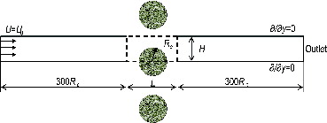
The air flow velocity inside the porous structure is small enough that air compressibility can be neglected. The influence of particles on the gas flow is also neglected due to their small concentration. The fluid flow in the homogeneous and porous areas in the approximation of the laminar viscous flow of incompressible gas is described by the equations (Bhattacharyya et al. Citation2006; Yu et al. Citation2011):[1]
[2] where
is the gas velocity; μ and ρ are coefficients of dynamic viscosity and air density; P is the pressure; ϵf is the porosity; k is the permeability of the porous medium. The coefficient β equals zero in the external area and equals one inside the porous cylinder. The gas velocity
, averaged with respect to the pore space volume, is connected with the filtration velocity
by the relation
. In the homogeneous area (ϵf = 1, β = 0) Equations Equation(1)
[1] and Equation(2)
[2] are the Navier–Stokes equations. Inside the porous body they represent the extended Darcy–Brinkman equations.
The system (1–2) is supplemented by the boundary conditions. The free-stream velocity U0 is given on the left boundary of the computational domain. On the right boundary of the periodic bar a pressure outlet boundary condition which is the downstream static pressure is taken. The upper and bottom boundaries of the computational domain including the porous cylinder zone represent a plane of symmetry.
2.2. Analytical Flow Model
The flow field in the array of cylinders at low Reynolds numbers can be obtained in an analytical form using the cell model proposed by Kuwabara (Citation1959). The cell model with Kuwabara boundary conditions was used by Stechkina (Citation1979), Kirsh (Citation2006b) to determine the velocity field of flow over the porous cylinder in the approximation of a small Reynolds number. Strictly speaking the cell model should be used for the periodic array of cylinders. We will apply it to describe the flow field for the periodic row of cylinders. The comparison of the inertial deposition efficiencies for the Kuwabara model and for fluid flow in a row of parallel cylinders showed a fairly good agreement (Kirsh and Stechkina Citation1977).
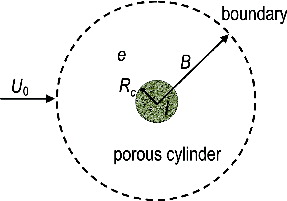
We will give the description and solution of the problem of fluid flow within the cell model following Kirsh (Citation2006b). Consider the flow of incompressible gas around a porous cylinder of radius in the cell of radius
(α = 1−ϵ,ϵ - porosity) (). At a low Reynolds number the flow of incompressible gas outside the porous cylinder is described by equations (Happel and Brenner Citation1965)
[3]
FIG. 2. Scheme of the cell model of Kuwabara.
The flow inside the porous body is defined by Darcy's equation:[4]
In Equations Equation(3)[3] and Equation(4)
[4] indices e and i refer to the values in the external and internal regions of the porous cylinder, respectively. Introducing the dimensionless quantities r = R/Rc, u = U/U0, pe = Pe Rc/U0μ, pi = Pi Rc/U0μ, Da = k/Rc2 we rewrite Equations Equation(3)
[3] and Equation(4)
[4] in the form
[5]
[6]
Equations Equation(5)[5] and Equation(6)
[6] are supplemented by conditions on the porous cylinder boundary r = 1 and on the cell boundary r = l = B/Rc:
[7]
[8] where
are the components of air velocity in cylindrical coordinate system.
Let be the stream function of the external flow. From EquationEquations (5)
[5] we get the biharmonic equation in polar coordinates:
[9]
The solution of (9) can be written as[10]
Taking the divergence of the Darcy EquationEquation (6)[6] , we obtain the Laplace equation:
[11]
The solution of (11) is written in the form[12]
Velocity components of the external flow are represented as[13]
To determine the equation for the gas pressure the first equation of (5) is written as[14]
Taking into account (10, 12–13) we get (14) in the form[15]
Integration of (15) gives the expression for the pressure[16]
Substituting (10, 12, 13, 16) into the boundary conditions (7–8), we obtain a system of algebraic equations for the undetermined coefficients in (10, 12). Solution of the system gives the following expressions
[17] where
is the Kuwabara parameter (Kuwabara Citation1959).
2.3. Equations of Particles Motion
The equations of motion of the aerosol particles taking Stokes aerodynamic drag into account, are written in the form[18] where
is the particle velocity,
is the vector of particle coordinates,
is the relaxation time of the spherical particle, ρp and Dp are density and diameter of the particle. The system (18) is numerically integrated using 4th order Runge–Kutta method in the velocity field obtained from the two developed models of fluid flow. For the numerical model the values of gas velocity at the current position of the particle trajectory are found by interpolation from the set of values of velocity components obtained from Equations (1) and (2). The components of gas velocity are calculated from (13) for the analytical model. The particle-laden flow considered is characterized by dimensionless parameters: the Reynolds number
, the Darcy number
, and the Stokes number
.
3. RESULTS OF CALCULATIONS
In typical aerosol filters the fibers are of several micrometers in size, while the size of fibers in wire screens reaches several hundred micrometers. In this work the cylinders with a radius μm are considered. The value of the free stream velocity corresponds to the Reynolds number
. The fluid flow Equations Equation(1)
[1] and Equation(2)
[2] are solved by the finite volume method using the FLUENT code.
The particles are traced starting in the undisturbed fluid at a distance x = 250 RC from the porous cylinder to calculate the deposition efficiency E. Particles are assumed to adhere upon contact with solid surfaces. In the general case, the quantity E can be expressed as the product of the deposition efficiency determined for the particles that reach the cylinder surface and the efficiency
of their deposition inside the porous body:
.
For the considered problem of inertial motion of particles the value is calculated as the ratio of the number
of particles reaching the surface to the total number
of particles in the cylinder cross section away from the surface:
[19]
The efficiency curves for the solid cylinder at a various values of the solidity are shown in . The comparison of obtained efficiencies with efficiency curves obtained by Müller et al. (Citation2014) shows good agreement. Examples of the streamlines of gas flow from the numerical model for two values of
and
are shown in . The streamlines at small Da are close to those for flow around a solid cylinder. For larger Da the air flow through the cylinder leads to an increase in the number of particles deposited on its surface by inertial impaction.
FIG. 3. Efficiency curves of solid cylinder for various from Müller et al. (Citation2014) (1, 3, 5) and present calculations by Fluent—2, 4, 6.
FIG. 4. Streamlines from numerical model : (1)
, (2)
.
The dependence of the efficiency on the Stokes number at the various Darcy numbers, obtained using the numerical and analytical models of the air flow, is presented in . The value Da = 0 corresponds to the solid cylinder where we have no air flow through the cylinder. In this case the efficiency of inertial deposition decreases to very small values close to zero at the small Stokes numbers (Brown 1993). For the porous cylinder,
is significantly greater than zero even for very small values of St. An increase of the Darcy number leads to a significant growth of the value
, for example, for the cylinder with the Darcy number Da = 0.1 the value
is equal to ∼0.28 at St = 0.01. This means that we can provide a large particle flux on the porous cylinder by increasing its porosity. It is seen that two flow models used give close results for small Darcy numbers. But the difference between
obtained from the two models increases with the growth of Da. This is due to the differences between the two fluid flow models in the porous zone. In the developed analytical model the approximate Darcy flow assumption is taken for the porous cylinder. A mathematical model of fluid flow (1–2) is based on the extended Brinkman equation inside the cylinder. For the Brinkman model, the tangential components of the fluid velocity at the porous cylinder boundary are forced to be equal. This increases the fluid flux to the porous cylinder. Because of this the deposition efficiency of inertialess particles will be higher for the numerical fluid flow model. The Kuwabara model with Darcy flow in the porous zone can be applied to calculate the fluid flow in the periodic row of porous cylinders for relatively small Darcy numbers.
FIG. 5. The dependence of (St) at
. Solid lines—analytical model (10,17), dashed lines—CFD calculations.
Müller et al. (Citation2014) proposed an approximate formula for the deposition efficiency of aerosol particles on a solid cylinder in a periodic array by inertial impaction and interception. The proposed formula is recommended for the range
(
is the interception parameter). We used this formula to construct a combined formula for the periodic array of porous cylinders for Re = 0. Because of this we will omit in the formula of Müller et al. (Citation2014) the dependence on the Reynolds number.
The deposition efficiency in the inertia-interception regime can be written as (Müller et al. Citation2014)[20]
where,
is the deposition efficiency due to interception. The comparison of the deposition efficiencies obtained with the use of the analytical fluid flow model (10,17) and from the formula (20) gives a new correction factor
for the modified Stokes number
From the analytical solution (10, 17) we can express the deposition efficiency of non-inertial particles (St = 0) as[21]
In the work of Müller et al. (Citation2014) the formula for the deposition efficiency by interception is used in the form
[22]
The formula (22) for was obtained using the Kuwabara model for the solid cylinder in the array (Brown Citation1993). In our case of the array of porous cylinders we can find the deposition efficiency
by interception as
[23]
A comparison of the dependencies and
for
is shown in . It is seen that the deposition efficiency due to interception for the porous cylinder is sligthly higher than that for the solid cylinder.
FIG. 6. The dependencies and
for
.
Using the formulas (20–23) we can construct a formula for the deposition efficiency as a function of a Stokes number, Darcy number, packing density and interception parameter[24]
The comparison of the deposition efficiencies obtained from the analytical model and from the approximate formula (24) is given in . It can be observed that the extended formula adequately describes the numerical results obtained from the analytical model (10,17).
FIG. 7. The dependence of on
at
. Solid lines—analytical model (10,17), dashed lines—formula (24).
Let the porous body be composed of n cylinders with the same radius whose permeability coefficient k can be expressed by the Kozeny–Carman formula (Nield and Bejan Citation1992):
The following expression for the Darcy number then can be written
[25]
The value Da = 0.1 can be provided for the fiber with Rc = 500 μm by various combinations of and n. For example, it is obtained for
μm at
.
The porous body can consist of spherical particles, for example a layer of deposited aerosol particles on the filter fiber. The estimation of the non-dimensional permeability (the Darcy number) and the Brinkman parameter for the porous medium created by deposited aerosol particles was considered by Kirsh (Citation1997) and Dunnett and Clement (Citation2009). Dunnett and Clement (Citation2009) used a range of Darcy numbers
to find the fluid flow through a porous layer. The Darcy number for the layer of deposited particles with
μm is in the range 0.02 < Da < 0.04 in the work of Kirsh (Citation1997). This means that the value Da = 0.1 can be obtained for real deposition layers.
As was mentioned earlier the particles reaching the porous cylinder can enter and deposit inside it or pass through the cylinder independent of its porosity. To find the efficiency of particle deposition inside the porous body, the particle trajectories in the interior area should be calculated taking into account the real porous structure. Let a porous cylinder in the considered row be composed of a random packing of n parallel cylinders with the same radius
μm. The fluid flow outside the porous body and in the interior porous medium is found by solving the Navier–Stokes equations of a steady state incompressible fluid. Conditions on the periodic cell boundaries are the same as for the numerical model described earlier. The calculation domain was meshed by an unstructured triangular mesh (a). Meshing provides convergence of the numerical solution with a relative residual of
. An example of particle trajectories is given in b. It is seen that some of the particles impact on separate elements inside the porous body. There are particles that go through the cylinder system and continue their motion with the air flow. The efficiency E of particle deposition due to inertial impaction was calculated directly by particle tracking in the flow outside and inside the porous cylinder. Calculations of deposition efficiency were repeated for several random arrays of cylinders to obtain the average values of E(St). The corresponding curves E(St) at Da = 0.1 and
are depicted in . The deposition efficiency
at Da = 0 (solid cylinder) is also shown. Apparently, the curve E(St) calculated from direct particle tracking through the porous body consisting of a random array of cylinders is in the intermediate location between curves
at Da = 0.1 and Da = 0. This means that the additional advantage in the total deposition efficiency E(St) for a porous cylinder decreases comparatively with
due to the motion of some particles that enter the porous body through the porous medium. A proportion of the particles are deposited by inertial impaction on the interior cylinders. Because of this we will have a higher deposition E(St) than
of a solid cylinder. The Darcy number Da = 0.1 corresponds to n = 22 and
(). Note again that the obtained numerical results correspond to an ideal two dimensional model of an array of parallel cylinders. The interior deposition by inertial impaction will be changed if we have another type of porous medium.
FIG. 8. The meshing (a) and particle trajectories (b) for St = 10, ,
, and
.
FIG. 9. The dependencies of (St) and
(St) at
. 1,2—
,
at Da = 0.1, and 3—
at Da = 0.
4. CONCLUSION
The problem of deposition of aerosol particles by inertial impaction in a periodic row of porous cylinders is solved on the basis of numerical and analytical models of fluid flow. The numerical model includes the Navier–Stokes equations outside and extended Darcy–Brinkman equations inside a porous cylinder. These equations are solved using the commercial FLUENT code. The Kuwabara cell model with Darcy's equation for a porous zone was used to write the fluid velocity components in analytical form. Aerosol particles trajectories are tracked in the air flow velocity field to calculate the efficiency of particle deposition by inertial impaction. Calculations show that the numerical and analytical models are in good agreement for small Darcy numbers. The difference between the models increases with the growth of the Darcy number.
Dependence of the deposition efficiency on the Stokes number is studied for various values of the Darcy number. It was shown that an increased air flow through the porous cylinder increases the particle flux on its surface. In the case of a solid cylinder, the particle flux to the surface decreases to very small values close to zero at small Stokes numbers. For a porous cylinder, even at very small St the particle flux to the cylinder surface will not be zero. An increase of the Darcy number leads to a significant growth of the particle flux to the porous body surface. But some particles that reach the porous cylinder surface may pass through the cylinder without inertial impaction inside it. To estimate the deposition efficiency inside the porous body the aerosol flow through a cylinder composed of a random packing of n cylinders with the same radius was calculated. It was found that the total deposition efficiency is bounded by the efficiencies of particle inertial capture with the surfaces of the porous and solid bodies. This means that the advantage in the total deposition efficiency of a porous cylinder relative to a solid one is diminished due to the ability of some of the particles that reach the porous body surface to pass through the porous medium without deposition.
The approximate formula for the deposition efficiency of aerosol particles on a solid cylinder in a periodic array by inertial impaction and interception proposed by Müller et al. (Citation2014) is extended for the case of porous cylindrical fiber. The formula gives the deposition efficiency as a function of the Stokes number, Darcy number, interception parameter and packing density.
NOMENCLATURE
| = | porous cylinder radius | |
| = | height of periodic cell | |
| = | length of periodic cell | |
| = | packing density of cylinders in the row | |
| = | gas velocity | |
| = | dynamic viscosity | |
| = | density of air | |
| = | pressure of air | |
| = | porosity | |
| = | permeability of porous medium | |
| = | coefficient of Darcy–Brinkman equations | |
| = | filtration velocity | |
| = | free-stream velocity | |
| = | radius of cell in Kuwabara model | |
| = | indices that refer to the values in external and internal regions | |
| Da | = | Darcy number |
| = | stream function | |
| = | polar coordinates | |
| Ku | = | Kuwabara parameter |
| = | particle velocity | |
| = | relaxation time of the spherical particle | |
| = | density of particle | |
| = | diameter of particle | |
| = | Reynolds number | |
| = | Stokes number | |
| = | particles deposition efficiency | |
| = | deposition efficiency of the particles reaching the cylinder surface | |
| Ei | = | deposition efficiency of the particles inside porous cylinder |
| nd | = | number of particles reaching the surface |
| = | total particles number | |
| = | interception parameter | |
| Stm | = | modified Stokes number |
| = | deposition efficiency of non-inertial particles | |
| = | deposition efficiency by interception | |
| = | deposition efficiency for porous cylinder |
Funding
The work was supported by the RFBR (Grant Nos. 15-01-06135, 14-01-31118).
REFERENCES
- Asgharian, B., and Chenh, Y. S. (2002). The filtration of fibrous Aerosol. Aerosol. Sci. Tech., 36:10–17.
- Bhattacharyya, S., Dhinakazan, S., and Khalili, A. (2006). Fluid Motion Around and Through a Porous Cylinder. Chem. Eng. Sci., 61:4451–4461.
- Brinkman, H. C. (1947). A Calculation of the Viscous Forec Exerted by a Flowing Fluid on a Dense Swarm of Particles. Appl. Sci. Res., A1(1):27–34.
- Brown, R. C. (1993). Air Filtration. An Integrated Approach Theory and Applications of Fibrous Filters. Taylor & Francis, Oxford.
- Chandesris, M., and Jamet, D. (2006). Boundary Conditions at a Planar Fluid-Porous Interface for a Poiseuille Flow. Int. J. Heat Mass Transfer. 49(13/14):2137–2150.
- Davis, R. H., and Stone, H. A. (1993). Flow Through Beds of Porous Particles. Chem. Eng. Sci., 48(23):3993–4005.
- Deo, S., Filippov, A., Tiwari, A., Vasin, S., and Starov, V. (2011). Hydrodynamic Permeability of Aggregates of Porous Particles with an Impermeable Core. Adv. Colloid Interf. Sci., 164(1/2):21–37.
- Dunnett, S. J., and Clement, C. F. (2009). A Numerical Model of Fibrous Filters Containing Deposit. Eng. Anal. Bound. Elem., 33:601–610.
- Dunnett, S. J., and Clement, C. F. (2012). Numerical Investigation into the Loading Behavior of Filters Operating in the Diffusional and Interception Deposition Regimes. J. Aerosol Sci., 53:85–99.
- Grigor’eva, O. V., and Zaripov, S. K. (2012). Inertial Deposition of Suspended Particles in a Flow Around a Porous Cylinder. Russ. Aeronaut., 55(1):19–24.
- Han, T., Haglund, J. S., Hari, S., and McFarland, R. (2009). Aerosol Deposition on Electroformed Wire Screens. Aerosol Sci. Technol., 43:112–119.
- Happel, J., and Brenner, H. (1965). Low Reynolds Number Hydrodynamics with Special Application to Particulate Media. Taylor & Francis, Englewood Cliffs.
- Hinds, W. C. (1999). Aerosol Technology: Properties, Behavior, and Measurement of Airborne Particles. 2nd ed. Taylor & Francis.
- Hosseini, S. A., and Tafreshi, H. V. (2010). Modeling Particle filtration in Disordered 2-D Domains: A Comparison with Cell Models. Sep. Purifi. Technol., 74:160–169.
- Kasper, G., Schollmeier, S., and Meyer, J. (2010). Structure and Density of Deposits Formed on Filter Fibers by Inertial Particle Deposition and Bounce. J. Aerosol Sci., 41(12):1167–1182.
- Kirsch, V. A. (1997). Aerosol Filters with Porous Fibers. Deposition of Inertialess Particles. Colloid J., 59(2):287–288.
- Kirsch, V. A. (2002). Inertial Deposition of Aerosol Particles in a Model Filter with Dust Loaded Fibers. The Journal of the Filtration Society, The Transactions of the Filtration Society, 2(4):109–113.
- Kirsch, V. A. (2006a). Stokes Flow in Model Fibrous Filters. Sep. Purif Technol., 58(2):288–294.
- Kirsch, V. A. (2006b). Stokes Flow Past Periodic Rows of Porous Cylinders. Theor. Found. Chem. Eng., 40(5):465–471.
- Kirsch, V. A. (2007). Deposition of Aerosol Nanoparticles in Filters Composed of Fibers with Porous Shells. Colloid J. 69(5):615–619.
- Kirsch, A. A., and Stechkina, I. B. (1977). Inertial Deposition of Aerosol Particles in Model Filters at Low Reynolds Numbers. J. Aerosol Sci., 8:301–307.
- Kuwabara, S. (1959). The Forces Experienced by Randomly Distributed Parallel Circular Cylinders or Spheres in a Viscous Flow at Small Reynolds Numbers. J. Phys. Soc. Jpn., 14(4):527–532.
- Lee, K. W., and Liu, B. Y. H. (1982). Theoretical Study of Aerosol Filtration by Fibrous Filters. Aerosol Sci. Technol., 1:147–161.
- Müller, T., Meyer, J., and Kasper, G. (2014). Low Reynolds Number Drag and Particle Collision Efficiency of a Cylindrical Fiber Within a Parallel Array. J. Aerosol Sci., 77:50–66.
- Nield, D. A., and Bejan, A. (1992). Convection in Porous Media. Taylor & Francis, New York.
- Ramarao, B. V., Tien, C., and Mohan, S. (1994). Calculation of Single Fiber Efficiencies for Interception and Impaction with Superposed Brownian Motion. J. Aerosol Sci., 25:295–313.
- Stechkina, I. B. (1979). Drag of Porous Cylinders in a Viscous Fluid at Low Reynolds Numbers. Fluid Dyn., 14(6):912–915.
- Stechkina, I. B., and Fuchs, N. A. (1966). Studies on fibrous Aerosol filters—I. Calculations of Diffusional Deposition of Aerosols in fibrous filters. Ann. Occup. Hyg., 9:59–64.
- Tien, C. (1989). Granular Filtration of Aerosols and Hydrosols, in: Butterworth Series in Chemical Engineering. Taylor & Francis, Stoneham, MA.
- Vasin, S. I., and Filippov, A. N. (2009). Cell Models for Flows in Concentrated Media Composed of Rigid Impenetrable Cylinders Covered with a Porous Layer. Colloid J., 71(2):141–155.
- Wang, J., and Pui, D. Y. H. (2009). Filtration of Aerosol Particles by Elliptical Fibers: A Numerical Study. J. Nanopart. Res., 11(1):185–196.
- Yu, P., Zeng, Y., Lee, T. S., Bai, H. X., and Low, H. T. (2010). Wake Structure for Flow Past and Through a Porous Square Cylinder. Int. J. Heat and Fluid Flow 31(2):141–153.
- Yu, P., Zeng, Y., Lee, T. S., Chen, X. B., and Low, H. T. (2011). Steady Flow Around and Through a Permeable Circular Cylinder. Computers & Fluids 42:1–12
- Zhu, C., Lin, C. H., and Cheung, C. S. (2000). Inertial Impaction-Dominated fibrous filtration with Rectangular or Cylindrical fibers. Powder. Tech., 112:149–162.