Abstract
We investigated the effect of inkjet operating parameters on the size control of aerosol particles. Droplets with agglomerates of polystyrene latex particles were generated from an inkjet nozzle and continuously dried up at the temperature of 38°C. When droplets have the size range of 30 to 70 μm in diameter, aerosol particles with the size range of 3.5 to 7.1 μm were generated after the drying process. We controlled the particle size easily within a factor of two by adjusting rising/falling time and voltages of an actuating waveform. Generated particles were shown to have a narrow particle size distribution. Thus, the particle concentration of aqueous suspension does not need to be adjusted precisely in order to control the size of generated aerosol particles.
Copyright © 2015 American Association for Aerosol Research
1. INTRODUCTION
Airborne microorganisms, fungal particles, and anthrax are well known for their harmful effect on human health (Douwes et al. Citation2003). Several studies have reported that human diseases and public health problems such as allergies (Samadi et al. Citation2013), asthma (Kumar et al. Citation2013), and cancer (Roodbari et al. Citation2013) can be caused by airborne bioaerosol particles. Also, transportation, coal combustion, cement manufacturing, metallurgy, and waste incineration produce harmful aerosol particles (Andreae and Rosenfeld Citation2008). Recent estimates for the current emission of these aerosols range from about 100 Tg/yr to about 200 Tg/yr. These aerosol sources have been widely monitored and regulated (Andreae and Merlet Citation2001). Since those public health problems and environmental problems have raised concerns over airborne aerosol particles, finding effective methods of detecting aerosol particles has become an important issue (Jung et al. Citation2009). Thus, an aerosol generator for monodisperse micron sized particles is necessary in order to improve the reliability of aerosol detecting equipments. Also, the aerosol generator can be used in new applications by aerosolizing suspended particles of various types or producing novel materials.
For this reason, several studies have been conducted on the generation of aerosol particles. Electro-spray uses high electric voltages between a nozzle and a ground plate to generate highly charged aerosol particles. The electro-spray can generate highly electrically charged aerosol particles and thus aerosol particles can be accurately controlled. Also, lower shear stress to the aerosol particle is an advantage of the electro-spray (Fu et al. Citation2011). Using an electro-spray, 0.3–20 μm sized aspirin particles were sprayed (Li et al. Citation2006). However, electro-spray has a problem of low concentration of aerosol particles and aerosol particles are also affected by high voltage (Wei et al. Citation2006). Vibrating orifice aerosol generator (VOAG) can generate highly monodisperse aerosol particles in the range from 1 to 200 μm. Piezo actuator vibrates an orifice and the vibrating orifice is used to break up liquid jet. Generated aerosol particles have uniform size, shape, density, and surface characteristics (Jensen et al. Citation1994). Using a VOAG, 3–20 μm sized fluorescent liquid oleic acid aerosol particles were generated (Kesavan et al. Citation2008). However, there are some problems with the VOAG: (1) the orifice is clogged frequently, (2) the generated particles contain some doublets (Iida et al. Citation2014), and (3) aerosol particles are affected by high pressure (Eisenberg et al. Citation2011). The above-mentioned aerosol generators have limits to generate aerosols with high concentration of monodisperse particles. Also, it is hard to guarantee the survivability of bioaerosol particles. For the evaluation of the performance of bioaerosol particle detecting equipments, it would be advantageous to have an aerosol generator that can generate size controlled monodisperse bioaerosol particles that are survivable during the generation process. Regarding the issue, an inkjet system does not require a high pressure that threatens the survivability of the bioaerosol particles. Also, the inkjet system can generate particles with uniform size and control the generation rate of particles by adjusting an actuation frequency. In addition, the volume of a droplet from the inkjet nozzle can be controlled to an accuracy of picoliter and inkjet nozzle can eject variety of materials with the viscosity range of 0.3–40 mPa·s.
In previous studies, Bottiger et al. Citation(1988), Dougherty et al. Citation(2007), and Iida et al. Citation(2014) used an inkjet system to generate aerosol particles. In those studies, the mass concentration of the solute in the solution was adjusted to control the size of the generated aerosol particles in inkjet aerosol generator. In Iida et al.'s Citation(2014) work, ultrapure water and isopropyl alcohol were used as the solvent of the inkjet solution. The concentrations of NaCl were 1.629, 202.4, and 21830 ppm, and the concentrations of EMI-TFMS (1-Ethyl-3-methylimidazolium Trifluoromethanesulfonate) were 2.214, 276.2, and 34150 ppm to generate 0.4–12 μm sized aerosol particles. In Dougherty et al.'s Citation(2007) work, percentage of glycerine in distilled water was adjusted from 0.1 to 1.0 in order to generate dried glycerine aerosol particles with the size range of 3 to 7 μm.
Another way to control the size of the aerosol particles using inkjet nozzle can be to control the droplet size for a given concentration of aqueous suspension. Droplet size can be controlled by adjusting the various parameters of the waveform applied to the piezo electric inkjet nozzle (Kwon and Kim Citation2007). Thus, this method can have an advantage of controlling the aerosol particle size easily and this method minimizes the number of solutions or suspensions with different concentrations to be prepared to generate a series of particle sizes.
Particle concentration in an aqueous suspension does not need to be adjusted precisely. Particle sizing instruments might have been calibrated using standard particles whose material is different from the particle material used in a specific application. It is difficult to know beforehand what solute (or particle) concentration in the aqueous suspension exactly generates the size seen by the particle sizing instrument. If our suggested method worked well, the inkjet aerosol generator could adjust the size seen by the particle sizing instrument to specific target size. As far as we know, whether the size of aerosol particles can be controlled by adjusting the waveform parameters of an inkjet system or not has not been investigated.
In this study, we aimed to control the size of generated aerosol particles by adjusting waveform parameters instead of adjusting the mass concentration of the solution. We chose to use polystyrene latex (PSL) particles as test material. The inkjet aerosol generator consists of an inkjet nozzle system and a drying module. The inkjet nozzle system was used to generate size controlled inkjet droplets and the drying module was developed to rapidly turn droplets into fully dried aerosol particles.
2. EXPERIMENTAL METHODS
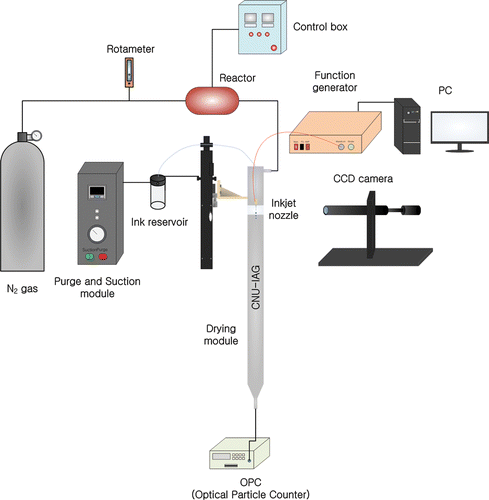
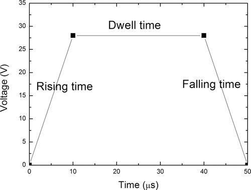
shows a schematic diagram of the experimental set-up. The primary components of the inkjet nozzle system are a piezo-type inkjet nozzle (Microfab, MJ-AT 50 μm), a reservoir, a function generator, a CCD camera, and an LED strobe. The solution used in our experiments was prepared as the mixture of 40 ml of de-ionized water (10 MΩ cm), and 4.2 ml of aqueous suspension of 1 μm PSL particles (Duke Scientific). The mixture was dispersed in ultrasonic bath (KODO, NXP-1002) for 1 h at 40°C. The concentration of prepared sample was 2.0 × 10⁹/cc. The aqueous suspension was dispensed in the form of droplets using an inkjet nozzle. The function generator transferred waveform signal with trapezoid shape to the inkjet nozzle. The waveform was controlled with input voltage and time step (Kwon and Kim Citation2007). As shown in , waveform is composed of rising time, dwell time, and falling time. Rising time is the time it takes for the voltage to rise to the input voltage, dwell time is the time period when the voltage is kept constant, and falling time is the time it takes for the voltage to decrease to zero voltage. When the rising step of the waveform was applied, the two negative pressure waves started to propagate in opposite directions from the center where the piezo is located. And when the falling step of the waveform was applied, the two positive pressure waves started to propagate in opposite directions from the center. After the generation of negative pressure, the positive pressure wave reaches the nozzle and the droplet is ejected (Kwon and Kim Citation2007).
In our experiments, the droplet size was controlled within the range of 30–70 μm by adjusting the various parameters of the waveform applied to the inkjet nozzle. The rising/falling time and the dwell time were adjusted in the range of 6–14 μs and 30–75 μs, respectively. The input voltage was adjusted in the range of 20–45 V.
In our experiments, droplets generated from inkjet nozzle were continuously dried up inside the drying module. When nitrogen gas was passed through the reactor, the temperature of the nitrogen gas was raised by heating coil inside the reactor. Heated nitrogen gas formed a sheath flow around an inkjet nozzle and carried the droplets downstream. The temperature of the nitrogen gas flow inside the drying module was set to 38°C. As nitrogen gas temperature is increased, de-ionized water evaporates and then PSL particles were agglomerated. And fully dried monodisperse particles with various sizes were generated.
For the determination of droplet speed, drop watcher system was used for acquiring strobe CCD camera images in order to measure droplet jetting speed. In order to measure droplet speed, two frozen droplet images were taken with a given time interval and then the droplet speed can be calculated from the two images. In order to check the size of PSL clusters, we connected optical particle counter (OPC, GRIMM 1.109) to the exit of the drying module and the particle counts were recorded continuously for 5 min. The highest particle concentration into the OPC was 1.2 × 10⁴ particles/l if there were no loss when the droplet generation rate was set to 500 Hz. The sampling flow rate of the OPC was 1.2 LPM and flow rate of the inkjet aerosol generator was 3 LPM. OPC (Grimm, 1.109) was calibrated with NIST certified PSL particles.
For the determination of particle morphology such as the diameter and shape, scanning electron microscope (SEM) images analysis was conducted using Image J software. SEM images were taken using JSM-7000F (JEOL). Information about the chemical composition of the water residues was obtained from energy dispersive X-ray spectroscopy (EDS; Oxford Instruments INCA X-sight LN2 EDS) analysis with a probe current of 10 nA, acceleration voltage of 15 kV, and working distance of 10.0 mm. In order to sample aerosol particles, americium (Am-241) and an electrical sampler (HCT-4650) were put at the exit of the drying module and PSL clusters were sampled on the Si substrate for 30 min at a voltage of 8 kV. The sampling flow rate of the sampler was equal to the aerosol flow rate exiting the drying module.
3. RESULTS AND DISCUSSION
In previous studies, Iida et al. Citation(2014) and Dougherty et al. Citation(2007) adjusted the mass concentration of the solute in the solution in order to control the size of the generated particles in inkjet aerosol generator. The relationship between solute concentration and particle size was investigated experimentally (Dougherty et al. Citation2007; Iida et al. Citation2014). Particle sizes increased with increasing solute concentrations.
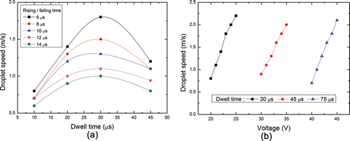
In this study, we controlled the size of generated particles by adjusting waveform parameters. We controlled the droplet size by adjusting the various parameters of the waveform applied to the inkjet nozzle. As shown in , various sizes of droplets can be generated by adjusting the various parameters of the waveform. Figures 3a and b show 30 μm droplet and 70 μm droplet generated from 50 μm inkjet nozzle, respectively. Droplet size was changed by waveform parameters. show the relationship between droplet speed and waveform parameters. As shown in , the droplet speed decreases with rising/falling time for a given dwell time when voltage is constant. As the rising/falling time increases from 6 to 14 μs, maximum droplet speed decreases from 1.8 to 0.8 m/s. When rising/falling time increases, the slope of the trapezoidal waveform decreases. The reduced slope makes the intensity of the pressure wave weaker and makes the droplet speed smaller. The water undergoes a resonating motion inside the inkjet nozzle when the dwell time is equal to 30 μs. As shown in , droplet speed increases with input voltage for a given dwell time when rising/falling time is constant. When voltage increases by 5 V for a given dwell time, the droplet speed increases nearly from 0.8 to 2.2 m/s. It is because the increased voltage makes the slope of the trapezoidal waveform steeper and thus results in the larger droplet speed. The amount of voltage required to achieve the same droplet velocity increases as the motion of water inside the inkjet nozzle deviate from a resonating mode, which occurs at dwell time being equal to 30 μs, to more interfering modes under longer dwell time. Results in confirm that the droplet speed can be controlled by the rising/falling time, dwell time, and voltage.
FIG. 3. CCD camera images of droplet under different waveform parameter: (a) rising/falling time: 10 μs, dwell time: 30 μs, voltage: 22 V, (b) rising/falling time: 8 μs, dwell time: 75 μs, voltage: 42 V.
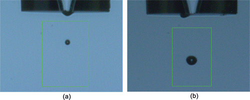
FIG. 4. Relationship between the droplet speed and waveform parameters: (a) droplet speed versus rising/falling time and dwell time and (b) droplet speed versus voltage and dwell time.
show the relationship between droplet size and waveform parameters. As shown in , the droplet size increases with voltage for a given dwell time and increases with dwell time when rising/falling time is constant. The droplet size increases from 27 to 32 μm, from 52 to 55 μm, and from 66 to 70 μm as the voltage increases when dwell time was set to 30 μs, 45 μs, and 70 μs, respectively. The droplet size increases as the voltage increases because the volume of water pulled back inside the nozzle increases as the shape of piezoelectric element is distorted to greater degrees under higher voltages and for longer dwell times. And as shown in , droplet size decreases with rising/falling time for a given dwell time and increases with dwell time for a given rising/falling time when voltage is constant. The droplet size decreases from 32 to 27 μm, from 55 to 52 μm, and from 70 to 66 μm as the rising/falling time increases when dwell time was set to 30 μs, 45 μs, and 70 μs, respectively. It is because when the dwell time increases, the intensity of the pressure wave increases during delay for pressure wave propagation. The increased intensity of the pressure wave makes the droplet size larger. Results in confirm that the droplet size can be controlled by dwell time, rising/falling time, and voltage. It is necessary to note that the droplet size can be mainly controlled by dwell time, not by the voltage and rising/falling time. With the above-mentioned waveform parameters, the inkjet nozzle can generate 30 μm and 70 μm sized droplets under stable jetting conditions. It is also important to find waveform parameters that can generate droplets without any satellite droplets. As the droplet speed increases, satellite droplets can be generated together with a main droplet. We found the proper range of waveform parameters as follows: when dwell time is 30 μs, the proper range of rising/falling time needs to be 6–14 μs and the proper range of voltage is 20–25 V. And when dwell time is 75 μs, the proper range of rising/falling time is 6–14 μs and the proper range of voltage is 40–45 V. The proper range of voltage may increase as the piezoelectric property of the inkjet nozzle deteriorates or the contaminants accumulate over a longer time period.
FIG. 5. Relationship between the droplet size and waveform parameters: (a) droplet size versus voltage and dwell time and (b) droplet size versus rising/falling time and dwell time.

Two sets of waveform parameters used in our experiments were determined. The first set has the rising and falling time of 10 μs, the dwell time of 30 μs, and the input voltage of 22 V. The second set has the rising and falling time of 8 μs, dwell time of 75 μs, and the input voltage of 42 V. In and , the first and second set of waveform parameters were used to generate 30 μm and 70 μm sized droplets, respectively.
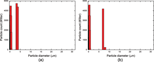
show size distribution of PSL microbead cluster according to the droplet size when aqueous suspension of 1 μm PSL particles with the concentration of 2.00 × 10⁹/cc was used. Average size of 3.5 μm and 7.1 μm PSL clusters were detected by OPC when 30 μm droplet and 70 μm droplet were ejected from inkjet nozzle, respectively. Generated PSL clusters were all shown to be monodisperse. As the size of the droplet was increased, the average size of the generated PSL clusters was also increased. Generated PSL cluster size can be varied within a factor of two by controlling droplet size.
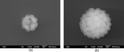
show SEM images of PSL microbead cluster according to the droplet size when aqueous suspension of 1 μm PSL particles with the concentration of 2.00 × 10⁹ /cc was used. Upon drying, the de-ionized water was evaporated, and the remaining PSL particles were agglomerated forming a microbead cluster. The size of the PSL cluster is 3.4 μm and 6.9 μm when 30 μm droplet and 70 μm droplet were ejected from inkjet nozzle, respectively. Nearly 45 PSL particles were agglomerated to form a 3.4 μm sized PSL cluster and nearly 360 PSL particles were agglomerated to form a 7.1 μm sized PSL cluster. As the size of the droplet was increased, the size of the generated PSL cluster was increased nearly by a factor of two. Also, we generated different size of droplets to change the size of PSL clusters. As the droplet size was increased, the average size of the generated PSL clusters was increased (See Supplemental Information 1 and 2).
Also, we checked the effect of concentration of aqueous suspension on the size of aerosol particles. We used aqueous suspension of 1 μm PSL particles with the concentration of 6.68 × 10⁸ /cc to check how much the size range of generated aerosol particles change. The same waveform parameters as in and were used. The average size of 2.4 μm and 4.9 μm PSL clusters were detected by OPC when 30 μm droplet and 70 μm droplet were ejected from inkjet nozzle, respectively. Also, SEM image analysis results confirmed that the average size of PSL clusters were 2.4 μm and 5.0 μm when 30 μm droplet and 70 μm droplets were ejected from inkjet nozzle, respectively. Nearly 15 PSL particles were agglomerated to form a 2.4 μm sized PSL cluster and nearly 120 PSL particles were agglomerated to form a 4.9 μm sized PSL cluster. Those results confirm that generated PSL cluster size can be still controlled within a factor of two when aqueous suspension with different concentration was used.
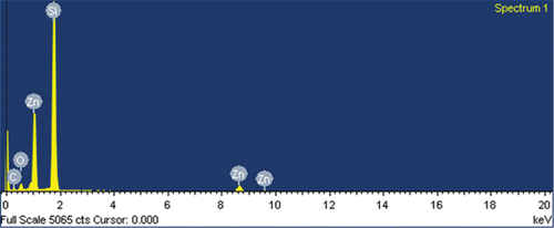
In , peaks appeared on the left side of the histograms were due to the water residue. We found the water residue was also generated with PSL clusters. Water residues were originated from the progeny droplets sputtered from the electrically charged surface of the evaporating droplets (Martin et al. Citation2008). The size of the water residues is 200–600 nm that there is no possibility of containing 1 μm PSL particle in progeny droplets. As shown in , EDS analysis result of water residue confirms that water residues are composed of C, O, and Zn. Also, a peak of Si was due to the Si substrate. The atomic percentage of residue was C (23.23%), O (10.71%), Si (52.60%), and Zn (13.46%).
5. CONCLUSIONS
In summary, we investigated the effect of inkjet operating parameters on the size control of aerosol particles. The size of aerosol particle was controlled by adjusting the size of a droplet generated by inkjet aerosol generator. And the droplet size can be controlled by adjusting waveform parameters like rising/falling time, dwell time, and input voltage. We generated monodisperse PSL clusters in the size range from 2.4 to 7.1 μm in diameter and the generated aerosol particle size was controlled approximately within a factor of two by adjusting the droplet size for a given concentration. This method gives us the advantage of controlling the aerosol particle size easily rather than adjusting concentration of the aqueous suspension.
SUPPLEMENTAL MATERIAL
Supplemental data for this article can be accessed on the publisher's website.
UAST_1115465_Supplemental_File.zip
Download Zip (707.4 KB)Funding
This research was supported by Agency for Defense Development (ADD-13-02-06-03).
REFERENCES
- Andreae, M. O., and Merlet, P. (2001). Emission of Trace Gases and Aerosols from Biomass Burning. Global Biogeochem. Cycle., 15(4):955–966.
- Andreae, M. O., and Rosenfeld, D. (2008). Aerosol-Cloud-Precipitation Interactions. Part 1. The Nature and Sources of Cloud-Active Aerosols. Earth-Sci. Rev., 89(1–2):13–40.
- Bottiger, J. R., Deluca, P. J., Stuebing, E. W., and Vanreenen, D. R. (1998). An Ink Jet Aerosol Generator. J. Aerosol Sci., 29:965–966.
- Dougherty, G. M., Hadley, D. R., O'Connor, P. R., and Bottiger, J. R. (2007). Engineered Aerosol Production for Laboratory Scale Chemical/Biological Test and Evaluation, Report No. UCRL-TR-230829. Lawrence Livermore National Laboratory (US), Livermore, CA, p. 28.
- Douwes, J., Thorne, N., Pearce, D., and Heederik, D. (2003). Bioaerosol Health Effects and Exposure Assessment: Progress and Prospects. Ann. Occup. Hyg., 47(3):187–200.
- Eisenberg, S., Nielen, M., Hoeboer, J., Bouman, M., Heederik, D., and Koets, A. (2011). MycoBacterium Avium Subspecies Paratuberculosis in Bioaerosols after Depopulation and Cleaning of Two Cattle Barns. Vet. Rec., 168(22):587–592.
- Fu, H., Patel, A. C., Holtzman, M. J., and Chen, D. R. (2011). A New Electrospray Aerosol Generator with High Particle Transmission Efficiency. Aerosol Sci. Technol., 45(10):1176–1183.
- Iida, K., Sakurai, H., Saito, K., and Ehara, K. (2014). Inkjet Aerosol Generator as Monodisperse Particle Number Standard. Aerosol Sci. Technol., 48(8):789–802.
- Jenson, P. A., Lighthart, B., Mohr, A. J., and Shaffer, B. T. (1994). Instrumentation Used with Microbial Bioaerosols. Chapman & Hall, London, UK, pp. 226–284.
- Jung, J. H., Lee, C. H., Lee, J. E., Lee, J. H., Kim, S. S., and Lee, B. U. (2009). Design and Characterization of a Fungal Bioaerosol Generator Using Multi-Orifice Air Jets and a Rotating Substrate. J. Aerosol Sci., 40(1):72–80.
- Kesavan, J., Bottiger, J. R., and McFarland, A. R. (2008). Bioaerosol Concentrator Performance: Comparative Tests with Viable and with Solid and Liquid Nonviable Particles. J. Appl. Microbiol., 104(1):285–295.
- Kumar, B., Gupta, G. P, Singh, S., and Kulshrestha, U. C. (2013). Study of Abundance and Characterization of Culturable Bioaerosol at Delhi, India. Int. J. Environ. Eng. Manag., 4(3):219–226.
- Kwon, K. S., and Kim, W. (2007). A Waveform Design Method for High-Speed Inkjet Printing Based on Self-Sensing Measurement. Sens. Actuat., 140(1):75–83.
- Li, S. W., Jayasinghe, S. N., and Edirisinghe, M. J. (2006). Aspirin Particle Formation by Electric-Field-Assisted Release of Droplets. Chem. Eng. Sci., 61(10):3091–3097.
- Martin, G. D., Hoath, S. D., Hutchings, I. M. (2008). Inkjet Printing – The Physics of Manipulating Liquid Jets and Drops. J. Phys.: Conf. Ser., 105, 1–14.
- Roodbari, A., Naddafi, K., and Javid, A. (2013). Measurements of Bioaerosols in the Air around the Facilities of Waste Collection and Disposal. Environ. Prot. Eng., 39(4):105–112.
- Samadi, S., Wouters, I. M., and Heederik, D. J. J. (2013). A Review of Bio-Aerosol Exposures and Associated Health Effects in Veterinary Practice. Ann. Agric. Environ. Med., 20(2):206–221.
- Wei, K., Zou, Z., and Yao, M. (2014). Charge Levels and Gram Fractions of Environmental Bacterial Aerosols. J. Aerosol Sci., 74(1):52–62.

