ABSTRACT
A light-weight, low-cost optical particle spectrometer for measurements of aerosol number concentrations and size distributions has been designed, constructed, and demonstrated. The spectrometer is suitable for use on small, unmanned aerial vehicles (UAVs) and in balloon sondes. The spectrometer uses a 405 nm diode laser to count and size individual particles in the size range 140–3000 nm. A compact data system combines custom electronics with a single-board commercial computer. Power consumption is 7W at 9–15 V. 3D printing technology was used in the construction of the instrument to reduce cost, manufacturing complexity, and weight. The resulting Printed Optical Particle Spectrometer (POPS) instrument weighs about 800 g with an approximate materials cost of 2500 USD. Several POPS units have been constructed, tested in the laboratory, and deployed on UAVs. Here we present an overview of the instrument design and construction, laboratory validation data, and field engineering data for POPS.
EDITOR:
Introduction
Atmospheric aerosols play many important roles in the environment. Consisting of microscopic particles suspended in the air, aerosols scatter and absorb sunlight, thereby exerting direct effects on climate (Anderson et al. Citation2003) and reducing visibility. Accumulation mode aerosols, which dominate impacts on visibility, also affect cloud formation, lifetime, and optical properties, resulting in indirect climate effects (Twomey Citation1974; Albrecht 1989; Pincus and Baker 1994). In addition, aerosols provide surface sites for heterogeneous chemical reactions (George et al. Citation2015) and negatively impact human health (Laden et al. Citation2006).
Understanding the sources and consequences of these aerosols requires accurate size-resolved measurements of aerosol particle concentrations. The mass median diameter of accumulation mode aerosol in the troposphere typically lies between 100 and 250 nm (Jaenicke Citation1993). Hence, a lower size detection limit close to 100 nm is highly desirable for significant coverage of this important mode of particles. Low-cost, light-weight, and low power consumption instruments are highly desired for balloon sonde and UAV work, possible broad-scale deployments and citizen science activities, and many other applications.
A common type of instruments for aerosol particle size measurements are optical particle counters (OPCs), (e.g., Chapter 15, Gebhart Citation2001) which use scattered light to measure the optical size of individual particles (Patterson and Whytlaw-Gray Citation1926) often at high time resolution. Various designs have been developed with a range of performance and complexity, some of which lend themselves to straightforward miniaturization. In this vein, we have previously reported a low-cost, high-sensitivity OPC prototype (Gao et al. Citation2013a). Now, we have further proved the design feasibility in the laboratory, improved certain elements (primarily in the light-collection optics used for detection) and constructed and deployed several working instruments. The improved OPC is practical for scientific applications; it is light-weight and low-cost; its construction is straightforward, and it is capable of measuring atmospheric aerosols over most of the accumulation mode size range. Largely constructed via 3D printing, the instrument is called the Printed Optical Particle Spectrometer (POPS). Here we present POPS details, with description of its optical system, air-flow management, construction, and performance specifications. Laboratory tests validating POPS performance are also provided.
Design and construction
General description
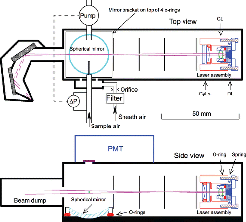
A schematic of the instrument (top and side views) is shown in . Individual aerosol particles in the sample flow are pulled through an inlet nozzle, and pass through a laser beam where they elastically scatter light. A fraction of the scattered light is collected with a spherical mirror and directed to a photomultipler tube (PMT) that generates an electrical current proportional to the amount of detected light. The PMT signal is digitized and the maximum current associated with each detected particle is recorded by a microcomputer. This maximum detected signal for a given particle, hereafter referred to as a “scattering amplitude,” is a measure of the particle's scattering cross section (i.e., optical size). Here we present four critical components of POPS design: the optical setup for producing an optimal laser beam and collecting light scattered by particles; the mechanical design necessary to provide a robust platform for the optics; a flow system to guide a known flow of sample aerosol through the laser; and a data acquisition system to interpret and store relevant information.
Optical configuration
The laser assembly is shown on the right side of . It consists of a diode laser, a collimating lens, and two cylindrical lenses. The laser and associated beam-forming optics are the same as those reported in Gao et al. (Citation2013a). A 405-nm laser diode (Sony SLD3234VF 100 mW or similar) is press-fit into a brass housing. A lens (C610TMW-A, Thorlabs, Inc.) is mounted in the same housing with a threading system to collimate the light into a beam. An o-ring (solid red ovals in , part #5233T15, McMaster.com) is used as a spacer, which locks the lens in place. Due to laser diode asymmetry, the resulting laser beam cross section is oval with short and long axes of ~1 mm and 3 mm at the exit of the diode assembly, respectively. The laser is oriented such that the long axis is vertical, and laser light is horizontally polarized (i.e., particles pass though the thinner dimension of the laser parallel to the direction of polarization).
A cylindrical lens (half of #69-724, Edmund Optics, , top view) focuses the laser beam horizontally 75 mm away at the crossing with the sample air jet. A second cylindrical lens (half of #69-722, Edmund Optics, , side view) focuses the laser beam vertically at a distance of 25 mm. The purpose of these cylindrical lenses is to maximize the signal-to-noise ratio and the uniformity of the vertical laser intensity at the jet crossing. The latter ensures that all particles passing through the jet experience nearly the same peak light intensity.
A miniaturized slit aperture (Gao, et al. Citation2013b) is used to reduce the vertical extent of the beam, and three additional apertures serve to block stray light. Slit dimensions are given in . The first slit aperture (next to the laser assembly) blocks the top and bottom 30% of the laser beam, resulting in a laser beam height of approximately 1.3 mm at the sample air jet. The air jet is less than 1 mm in diameter, thus is completely intercepted by the laser beam with relatively uniform light intensity. After adjustment, each of the four slit apertures is locked in place for mechanical stability.
Table 1. Slit aperture dimensions and positions.
A spherical mirror (25 mm diameter, 10 mm focal length, #43-464, Edmund Optics) is used to collect laser light scattered by particles. The distance between the center of the air jet and the center of the mirror is ~14.3 mm. This distance determines the maximum collection angle range (38°–142° from the laser beam direction) and the dimensions of the resulting image reflected onto a PMT (Hamamatsu H10720-110). The mirror mount rests on four o-rings at the corners and is held down by four screws, allowing the orientation of the mirror to be adjusted by tightening or loosening the four screws. This arrangement enables the reflected light to be directed through a circular 5 mm diameter aperture to the PMT (which has an 8 mm diameter active area). The aperture diameter is large enough to allow all light scattered by particles to be collected, yet small enough to reduce background light from reflections and Rayleigh scattering by more than a factor of 2 at 830 hPa.
The laser beam is extinguished in a beam dump after exiting the particle detection region. The laser encounters a 3-mm thick neutral density filter (17.5 mm × 17.5 mm, cut from a 50 mm × 50 mm blank #48-098, Edmund Optics, optical density = 3) oriented at the Brewster's angle, which optimizes absorption of the polarized light. A small fraction of the light is reflected to a second, 2-mm thick neutral density filter (17.5 mm × 17.5 mm, cut from a 50 mm × 50 mm #48-097, Edmund Optics optical density = 2) also oriented at the Brewster's angle. Any light reflected from the second filter enters an angle light trap that is painted black (MH2200 Black Paint, Alion Science and Technology, McLean, VA, USA).
Mechanical configuration
The mechanical design of the POPS is critical for ensuring stable optics, ease of optical adjustments, and overall compactness. The optical system described above is housed in a 3D-printed plastic enclosure (thick black lines in ). The enclosure is airtight, enabling stable sample flow and preventing aerosol contamination. The body of the enclosure (excluding the beam dump) is an open box with a separate cover. The box design provides a stiff, stable platform for all optical components, and ease of access for assembly and adjustment.
Mechanical adjustments are needed for laser beam collimating, laser beam steering, movements of slit apertures, and spherical mirror positioning. Laser beam collimating is performed outside of the POPS enclosure, before the laser beam assembly (blue parts, far right, ) is integrated into the housing (red part, far right, ) with three screws and a high-load compression spring (part #1561T29, McMaster.com). The laser beam is aimed at the sample air jet and the center of the beam dump by tightening and loosing these screws. Each slit aperture is adjusted using two screws (Gao, et al. Citation2013b), one allowing vertical translation, and the other horizontal. The adjustments of these side screws, as well as the laser pointing, are done through threaded (#4–40) through-holes on the enclosure walls. These holes are sealed with o-ring screws (part #90825A140, McMaster.com) during normal operations.
3D printing
The enclosure and optics mounts of the instrument are designed to minimize their volume and weight, making them fairly complex. Manufacturing these parts with conventional machining would be difficult and costly, especially in limited number. We instead produce these parts using 3D printing technology, which is approximately an order of magnitude less expensive, very fast, and easily applied to additional small construction batches without large additional costs. Because so much of the structural and component mass was printed, the instrument has been named the Printed Optical Particle Spectrometer (POPS).
Various 3D printing technologies were explored during development. Cost, speed of manufacture, suitability of materials, and suitability of the resulting parts were all considered. For example, fused deposition modeling, although very cost effective, cannot consistently provide airtightness and, therefore, is not suitable for this application. Plastic printing was chosen in this work as providing an optimal balance between the cost and the quality of the resulting parts. As the enclosure and internal parts must be opaque with black internal surfaces to prevent light contamination, printed plastic parts that are semitranslucent or reflective must be painted and, therefore, those materials must be compatible with paint.
For this work two types of printing work well. The first is stereolithography with an acrylic-glass-like material (3DSystems Projet 1500, http://www.3dsystems.com). The material can be tapped for threaded holes, but due to its brittleness, protective Helicoil inserts (e.g., Part #91732A201, McMaster.com) must be used for durability. The second, slightly more expensive, option is Selective Laser Sintering of Nylon (e.g., http://www.buildparts.com/materials/duraformpa). This material is much stronger, and Helicoil inserts are not necessary. A further advantage of the Nylon is that it is about 30% lighter than the acrylic-glass-like material. For both materials MH2200 Black Paint (Alion Science and Technology, McLean, VA, USA) was used as surface treatment applied before assembly of the instrument.
Air-flow management
A miniature rotatory vane pump (G 6/01-K-LCL, http://www.thomas-masterpieces.com/product-p/50027.htm) is used to pull sample air through a nozzle into the instrument. The nominal inner diameter (ID) of the nozzle is 0.81 mm (0.032 inch). The upper limit of the sample flow rate is about 3 volumetric cubic centimeters per second (vccs) for this nozzle geometry. The combination of flow rate and nozzle ID determines the transit time (here typically 5 µs) for a particle crossing the laser beam. A transit time shorter than 1 µs would make signal processing difficult with the electronics used in POPS.
A laminar flow element (LFE) coupled with a differential pressure (ΔP) sensor (Alpha Instruments 163W0R 25D5F2A) is used to measure the sample flow rate. The ΔP signal is used to servo control the pump to obtain constant volumetric flow. The LFE is constructed with brass tubing (3.2 mm (1/8 inch) OD, 1.6 mm ID, Onlinemetals.com) as shown in . Two pressure taps are soldered on the main tubing, about 60 cm apart. The diameters of the pressure ports are about 0.34 mm.
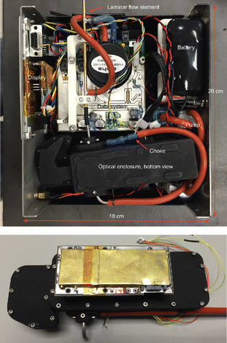
Figure 2. Top panel: A complete and functional POPS instrument configured for desktop operation (i.e., configured for convenience with a large battery for up to 5 h operation and an LCD display but not for low weight, cover removed). Bottom panel: The optics box with the scattering signal digitizer board (shielded by a grounded brass EMI cover).
In addition to the sample flow, a sheath flow is drawn through a particle filter (DIF-MN40, United Filtration Systems, Inc.) into the optical enclosure due to the low pressure created by the pump. This flow keeps the enclosure clean and allows the internal pressure of the system to follow ambient pressure changes. The sheath flow is not directly controlled, but is limited with an orifice (~0.8 cm diameter, Air Logic F-2815 series) to ∼2–3 vccs. Six 0.7-mm holes on the enclosure wall (two are shown in , top view) disperse the sheath flow evenly around the sample flow. Under normal flow conditions, the pressure inside the enclosure is a few hPa below ambient pressure.
Electronics
Four custom electronic circuits are used to control air flow, control laser current, digitize PMT signals, and communicate the digitized data to the computer (NI sbRIO 9606, National Instruments, Austin, TX, USA). Scattering peak amplitudes can be determined either in post processing or in real time. This can be done directly with special electronic hardware (Hill et al. Citation2008), or indirectly via fast digitization of the PMT output and real-time extraction of peak information with software running on the computer. A third possibility, which we did not explore, is by storing the raw time-series scattering data associated with individual particles for later analysis (Schwarz et al. Citation2010). The hardware solution is generally less expensive to produce but may be difficult to develop and debug. We have so far used the software solution because it is more flexible, and can provide additional information about instrument performance such as flow speed and noise. With this choice, a custom signal conditioning and digitization circuit converts the PMT current to a voltage (0–5 VDC), digitizes the voltage at 16-bit resolution (65536 linear digitizer bins) at 4 MHz, and continuously provides the digitized information to the computer. A software routine running on the computer analyzes the digital signals to identify pulses. Pulse arrival time, amplitude, and signal width (i.e., duration) are stored on a USB memory stick. The computer can also store raw data segments for subsequent instrument performance evaluation. We note that in the future the hardware solution should be considered for cost reduction in future versions since instrument performance is now adequately understood.
The data system is able to analyze every detectable particle in air arriving at a rate less than 10,000 particles s−1; most air even in urban areas meets this criterion. For higher particle rates, the data system can selectively skip 1–100 particles before analyzing the next particle. With a 5 µs transit time, the probability of scattering signal overlap by two consecutive particles only becomes significant (~10%) when the particle detection rate approaches 20,000 particles s−1. For air that contains more than 7000 particles cm−3, a nozzle with a smaller ID and a lower flow than 3 vccs should be used. Note that, for a given nozzle diameter, reducing sample flow does not reduce the probability of signal overlap. This is because although reducing the flow slows the rate of particles passing through the laser beam, it also increases the transit time of an individual particle passing through the laser beam. For clean air, the nozzle ID could be increased to allow higher flows and therefore higher particle count rates, but should not exceed 1.6 mm without modifying the laser shape, which is set by the light-blocking apertures as described above.
Performance
A functional POPS instrument configured for desktop operation (i.e., configured for convenience but not for low weight/power usage) is shown in . Instrument specifications are listed in , followed by discussion of the critical characteristics.
Table 2. Specifications of the light-weight/low power realization of the POPS instrument.
Size resolution
The optical size of a particle is determined from the maximum intensity of laser light that it scatters. Uncertainty in a particle's physical diameter as determined from scattered light in POPS is fundamentally limited by variations of particle index of refraction, Mie resonances, assumptions of sphericity, and by random variability in scattering amplitudes.
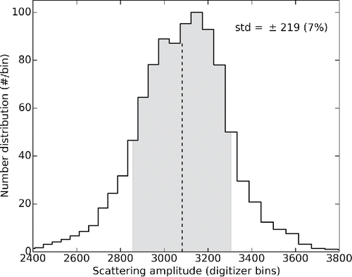
Commercially available polystyrene latex (PSL) spheres have very narrow size distributions (4% or less) and a well known index of refraction. PSLs were used to evaluate the POPS's size resolution. As shown in , a histogram of scattered light amplitudes from 510 nm PSLs, the standard deviation of the scattering amplitude is about 7%, which corresponds to ~3% in diameter (worst case, assuming that scattering amplitude is proportional to diameter to third power).
Figure 3. A histogram of scattering amplitudes from 510-nm polystyrene latex (PSL) spheres. The standard deviation of the scattering amplitude is about 7% (shaded area indicates data points within one standard deviation), which corresponds to ~3% in optical diameter for this size particle in the POPS.
Signal dynamic range
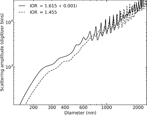
The most significant change from our original design (Gao et al. Citation2013a) is in the geometry for the collection of scattered light. The new design (which uses a spherical mirror to collect light scattered sideways instead of a focusing lens to collect forward scattered light) is more sensitive for particles below 200 nm in diameter, and less sensitive to larger particles. The significant advantage of the new design is that a smaller signal dynamic range (defined as the ratio of signals from the largest and smallest measureable particles) is required to span the desired particle size range. The theoretical response of the instrument to two types of particles, PSL spheres and dioctyl sebacate (DOS) spheres was calculated using Mie theory (Mie 1908) (). With the reduced signal dynamic range, a single 16-bit digitizer is now sufficient for the entire desired detection range (140–3000 nm), including optical and electronic noise.
Figure 4. Scattering amplitudes for PSL spheres and dioctyl sebacate (DOS) calculated using Mie theory as a function of particle diameter. The laser wavelength is 405 nm and the indices of refraction of particles for PSL and DOS are 1.615+0.001i and 1.45, respectively. Oscillations at diameters larger than 600 nm are due to Mie resonances.
Detection limits
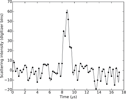
The laser diodes used are rated at 100 mW, yet we operate them at only ~60 mW constant power output for easy thermal management. Approximately 25 mW laser power passes the four slit apertures. The peak laser intensity at the aerosol jet is sufficient for the PMT to detect particles far smaller than 140 nm, but only in the absence of stray laser light, which degrades the signal-to-noise ratio. The stray laser light results in both a constant offset and superimposed high frequency noise in the PMT output. The amplitude of the high frequency component is comparable to the offset. This noise is similar to that observed in the previous work (Gao et al. Citation2013a) and is often indistinguishable from pulses caused by small particles. The majority of stray light comes from Rayleigh scattering by air molecules, evidenced by a marked decrease (>2×) in noise when the enclosure is evacuated to lower than 100 hPa. The remaining stray light is due to diffraction from slit apertures and imperfect light trapping by the beam dump. The smallest DOS particle measureable with 100% efficiency (verified with an UHSAS instrument, Droplet Measurement Technology, Inc, Boulder, CO, USA) with a signal-to-noise ratio of >5 at 830 hPa (for robust noise rejection) is 140 nm in diameter (). Note that DOS has a real refractive index of 1.45 (Pettersson et al. Citation2004).
Figure 5. A time series of the optical signal intensity; the peak was produced by a 140-nm DOS particle crossing the laser.
Note that the primary source of noise in the original prototype (Gao et al. Citation2013a) was also likely due to Rayleigh scattering, and that the cause of the high frequency noise has not been determined. Low levels of light from an LED and an incandescence bulb caused similar high frequency noises, suggesting that it is a feature of the PMT and/or detection electronics.
The upper size limit is set by the digitizer's upper voltage limit once the gains of the PMT and its preamplifier are set for unambiguous detection of the smallest particle (140 nm). For DOS particles the upper limit is 3000 nm.
Calibration
Two materials (polystyrene latex [PSL] spheres and DOS) have been used to calibrate POPS and to test our theoretical understanding of the optical design. The relative optical signals calculated using Mie theory are shown together in and separately in and . Indices of refractions are set at m = 1.615+0.001i for PSLs (Washenfelder et al. Citation2013) and 1.45+0i for DOS (Pettersson et al. Citation2004) at the assumed laser wavelength of 405 nm (the exact laser spectrum was not measured). DOS particles were size-selected using a differential mobility analyzer (DMA). As the conversion of light intensity to signal voltage in the instrument is not independently calibrated, we scale the theoretical results using PSL particles. Theory then predicts the behavior of the DOS particles very well (shown in ), indicating that the optical configuration is adequately understood.
Figure 6. Calibration data using PSL spheres (solid circles, vertical error bars indicate the uncertainties in amplitude determination (Figure 3). PSL diameter uncertainties are 4% or less). The optical signals calculated using Mie theory are also shown. The Mie calculations are scaled to the calibration results. The same scaling factor is also used in Figure 7.
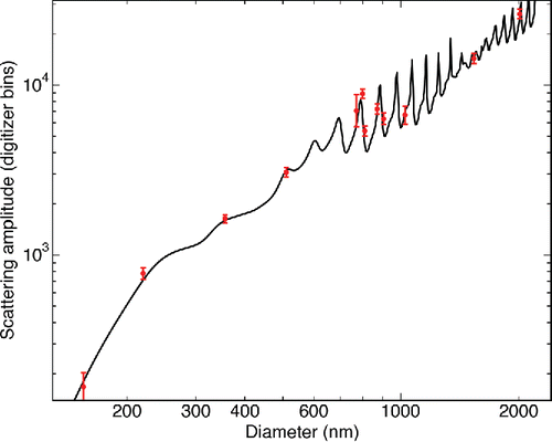
Figure 7. Calibration data using DOS (solid circles, horizontal and vertical error bars indicate the uncertainties in DMA size selection and amplitude determination, respectively). The DOS particle sizes were selected using a differential mobility analyzer. The optical signals calculated using Mie theory are also shown. The scaling factor for the Mie calculation is derived from the PSL results.
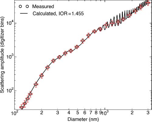
Oscillations in the scattering signals with particle diameter above 600 nm are due to Mie resonances (van de Hulst 1981) and are clearly visible in the PSL calibration. Oscillations in the DOS data are not clearly visible because the DMA size selection results in wider particle size distributions than are achieved with commercial monodisperse PSL preparations. Four sizes of PSL spheres between 771 and 903 nm demonstrate the oscillations in the real signal. Note that these oscillations create ambiguity in the determination of particle diameter for spherical particles larger than 600 nm diameter. This ambiguity is a dominant contributor to measurement uncertainty in some size ranges (see further discussion in the “Uncertainty analysis” section below).
The POPS is calibrated using a calibration material at various diameters. The calibration material is usually DOS particles as shown in . Spline interpretation is used between the calibration data points. The data collection algorithm uses the calibration to establish a one-to-one relationship between the scattering amplitude (in the unit of digital bins) and particle size, which is critical in the Mie resonance region. When a particle is sampled by the POPS, its size is determined from its scattering amplitude using this one-to-one relationship. See further discussion in the “Uncertainty analysis” section below.
Robustness
The performance of POPS depends on the stability of the optical alignment. As described above, all mechanically adjustable components are either locked in place using screws, or spring loaded (by either springs or o-rings). An initial concern was that printed plastic parts, especially the optical enclosure, might deform over time and cause optical misalignments. Thus far, experience shows that some parts do warp noticeably immediately after production (within 1 day), but no further deformation has been observed for either printing material over timescales up to 7 months for the oldest copy. Two POPS units did not show any noticeable performance changes after experiencing commercial shipping and several launches and landings onboard a small UAV. Hence, the mechanical system is sufficiently stable for all anticipated uses. Longer-term (>1 year) stability information is not yet available due the short history of the instrument.
Deployment of POPS on small UAVs and weather balloons requires a system with low susceptibility to electromagnetic interference (EMI) because close proximity to the navigation and communication systems is unavoidable for these applications. On an initial deployment, severe interferences in the POPS electronics arose from the radios of a Manta UAV and an i-Met radiosonde and the POPS electronics interfered with the Manta differential GPS receiver. The current versions of the POPS electronics boards have all been designed such that grounded metal covers can be added (). These metal covers have eliminated the EMIs on and from the POPS.
Uncertainty analysis
For particle number concentration measurements the main uncertainties are from sample air flow measurement and particle detection efficiency. The flow rate is monitored with an LFE and a differential pressure (ΔP) meter. The LFE-ΔP combination can be calibrated to better than 5%. The ΔP meter is temperature compensated between 0 and 70°C. Tests from 1013 hPa down to ~50 hPa revealed no pressure dependence in the LFE calibration.
When two particles pass through the laser beam at the same time, their scattering signals overlap in time. The peak detection software is not able to separate the signals from the particles and as a result only one “composite” particle will be recognized. These coincident events are negligible until the average inter-arrival time of particles is less than approximately 10 times the particle transection time across the laser beam, i.e., about 50 µs (20,000 particles s−1). Nozzle diameter and flow rate should be adjusted to keep the anticipated count rate below this limit as discussed before. A second cause of missing counts is the software speed limit (). Currently the upper limit of software counting is 10,000 particles s−1. Selective analysis is preprogrammed. Users can elect to skip 1–100 particles between subsequent particle anayses. This tool can also reduce data storage demand for long-term measurements.
A number of uncertainties are associated with particle size determination. The first uncertainty (scattering amplitude uncertainty) is in scattering amplitude determination as demonstrated in . The 7% scattering amplitude uncertainty as shown corresponds to approximately 3% uncertainty (1 σ) in particle diameter at 500 nm. The second source of uncertainty (Mie resonance uncertainty) is caused by Mie resonances and can exceed 15% in diameter (>30% in scattering amplitude) for particles larger than 600 nm. The last uncertainty (IOR uncertainty) is due to the dependence of the scattering amplitudes of small particles (<~600 nm) on the index of refraction (an example is given in ). Composition of aerosol particles can be complex, especially in the lower troposphere. Since POPS can only assume one value for the index of refraction, errors in size determination could be very significant for particles less than 600 nm. We note that these uncertainties are common to all optical sizing methods, but vary in severity depending on the optical configuration, laser polarization, and laser wavelength. We do not address the uncertainties associated with nonspherical particles.
The exact combined uncertainty of sizing any individual particle is not relevant in the context of measurements on an aerosol population. Instead we examine the effect of the uncertainties listed above in determination of the size distribution of a hypothetical aerosol particle population that closely resembles an ambient aerosol population. The hypothetical population has two log-normal modes; one corresponding to the accumulation mode, and another to the coarse mode (an approach similar to Brock et al. Citation2011). The POPS is assumed to be calibrated using DOS particles as shown in , with spline interpretation used between the calibration data points. In our analysis of the hypothetical set up, each particle sampled by the POPS is sized using the DOS calibration regardless of its assigned composition with and without accounting for the scattering amplitude uncertainty. Four populations of particles are considered here: pure DOS, pure ammonium sulfate (AS, IOR = 1.53, Washenfelder et al. Citation2013), pure black carbon (BC, without a coarse mode component, (Schwarz et al. Citation2006, Park et al. Citation2008), IOR = 2.26+1.26i from Moteki and Kondo Citation2010), and an external mixture (by number) of DOS (45%), AS (45%) and BC (10%, which is on the high side of measured BC number fraction [Schwarz et al. Citation2006]). The results are shown in . Errors (difference between the hypothetical and simulated measurement) of modal parameter and total particle number, surface area, and volume between 140 and 3000 nm are listed in . The Mie resonance uncertainty causes large errors in general, but these errors are mostly localized (in the diameter space) in the coarse mode. Interestingly, the Mie resonance-induced localized errors are largely canceled by the errors caused by the scattering amplitude uncertainty (grey lines vs. black lines in ).
Figure 8. Distortions to hypothetical aerosol size distributions that are measured by a POPS due to the scattering amplitude, Mie resonance, and IOR uncertainties. Blue and black lines represent the original and as-measured-by-POPS distributions. Grey lines are as-measured-by-POPS distributions without taking the sizing uncertainty into account. Red lines are lognormal fitting results to the accumulation and coarse modes. See Table 3 for detailed error analysis results.
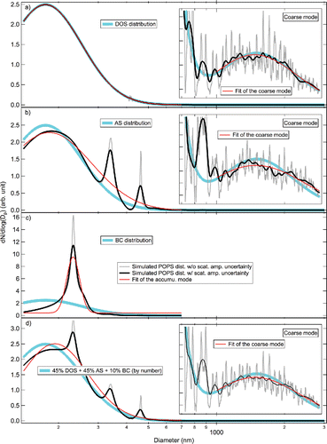
Table 3. Percent errors of model parameter determinations and total particle number between 140 and 3000 nm due to the scattering amplitude, Mie resonance, and IOR uncertainties. N, SA, and V stand for total number, surface area, and volume of particles between 140 and 3000 nm, respectively.
The IOR uncertainty does not apply in the DOS case. Since the scattering amplitude uncertainty is very localized in the diameter space and, therefore, does not affect the mode parameter determination, the errors in the DOS case as shown in are solely due to the Mie resonance uncertainty. As shown, the Mie resonance uncertainty causes only very small errors to the accumulation mode and total number, surface area, and volume. For the coarse mode, the largest effect of the Mie resonance uncertainty is the broadening of the mode by 14%.
The IOR-uncertainty induced errors in mode parameters and total number, surface area, and volume increase with the increase of mismatches of assumed (1.45 for DOS) and real indices of refraction (1.53 for AS and 2.26+1.26i for BC) and are quite significant for AS and BC if the assumed (calibration) material is DOS. These case studies show clearly that choice of calibration material is critical to optimally accurate measurements. To the degree that IOR uncertainties exist, errors can be substantial. We note that this caution extends to the most optical particle counters. Interestingly, mismatching indices of refraction of the calibration material and ambient aerosol may produce distinct large peaks in measured particle size distributions on top of the accumulation mode as shown in , Panels b, c, and d. Note that these peaks are also closely related to the Mie resonances. We speculate that these peaks may be used to determine effective index of refraction of the ambient aerosol in special cases where the chemical composition of the aerosol is uniform. We note that since individual scattering peaks are recorded by POPS, data can be analyzed, ex post facto, for the most appropriate index determined by other measurements.
In the atmosphere, aerosol are most often internally mixed (Murphy et al. Citation2006; Schwarz et al. Citation2006) and the indices of refraction are likely to be a continuous distribution instead of a few discrete values as considered above. In this case the error estimation method shown above still applies, but the full range of indices of refraction must be taken into account. We note that the three examples given above (DOS, AS, and BC) represent the lower, mid, and upper values of IOR in the real world (Dick and McMurry Citation2007). The only exception is water, whose IOR is about 1.34.
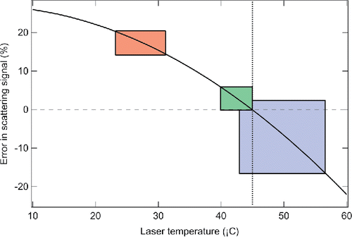
The optical configuration is stable against ambient temperature changes. The diode laser and the PMT are not temperature regulated, leading to temperature-dependent variations in laser intensity (which have been measured in the laboratory) and PMT sensitivity (–0.4%/°C,http://www.hamamatsu.com/resources/pdf/etd/PMT_handbook_v3aE-Chapter13.pdf). Since the scattering signal is directly proportional to the laser beam intensity, the laser intensity is a source of uncertainty. Based on measured laser temperature variations during balloon flights, we estimate this uncertainty using the laboratory sensitivity study. shows the temperature-induced scattering amplitude errors for five balloon flights. The corresponding maximum size errors are about ±9%.
Figure 9. Error in scattering amplitude is shown as a function of laser temperature. Dotted line indicates the laser temperature during calibration. Three boxes indicate three temperature ranges the POPS laser experienced in winter, spring, and summer.
The last uncertainty that has not been addressed above is the counting statistics, which is dependent on the ambient aerosol loading, number of size bins, and counting time. Statistical analysis has been studied extensively (Bevington and Robinson Citation1992) and, therefore, is not discussed in detail here.
Intercomparison with other instruments
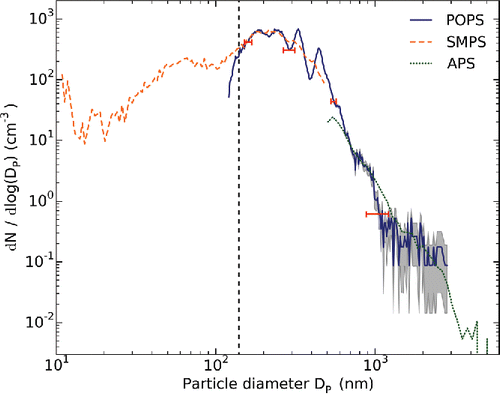
The POPS has been compared to a number of veteran instruments (ultra-high sensitivity aerosol spectrometer [UHSAS] from Droplet Measurement Technologies; laser aerosol spectrometer [LAS], scanning mobility particle sizer spectroemeter [SMPS], and aerodynamic particle sizer [APS], all by TSI, Inc, Sureview, MN, USA). One example is given in (POPS, SMPS, and APS). All three instruments sampled air pulled from a common inlet (Bates et al. 2013). The data shown are 10-min averages. POPS was calibrated using DMA-selected DOS particles as shown in . The difference between SMPS and POPS increases rapidly below 140 nm (vertical dashed line), consistent with the 140 nm POPS lower detection limit.
Figure 10. Intercomparison of POPS, SMPS, and APS. All three instruments were sampling air pulled from a 12.5-m inlet. The data shown were 10-min averages. Vertical dashed line indicates the POPS lower detection limit with 100% detection efficiency. Grey shading indicates the POPS counting uncertainty. Horizontal bars represent POPS sizing uncertainties.
Continuous data collection
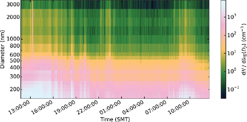
The POPS has been used to collect data continuously for up to three days. An example is given in . The POPS was placed at the rooftop of the 3-story NOAA laboratory building in Boulder, CO, and collected data continuously for 24 h.
Conclusions
We have designed and built multiple copies of a light-weight low-cost optical particle counter called the Printed Optical Particle Spectrometer (POPS). The detection range of the POPS is from 140 nm to approximately 3000 nm. Weighing less than 1 kg, it is particularly suitable for balloon- and small-UAV-borne atmospheric profiling. Other applications of the POPS include ground-based and tethered-balloon PM2.5 monitoring.
POPS is relatively low-cost (~$2500 excluding labor), may be constructed, aligned, and calibrated in ~3 work days, while still sensitive and robust. The use of 3D printing significantly reduces the total cost.
Software-based peak detection is currently adopted for its flexibility to changes in optical signals during the instrument development. However, the current data system accounts for about 60% of the total cost and significant future reduction in cost is quite possible with an improved design and a less expensive computer.
Statistical analysis of the measurement uncertainties on hypothetical aerosol populations indicates that errors due to Mie resonances do not exceed 1.5% for the accumulation mode parameters and total number, surface area, and volume values between 140 and 3000 nm. The coarse mode is affected by the Mie resonances more severely, resulting in errors of +6.6%, –1.9%, and +14% for modal peak, location, and width, respectively. Errors due to IOR uncertainty depend on the selection of the calibration material. A mismatch between the indices of refraction of the calibration material and aerosol may lead to very large errors.
Several inter-comparisons with established instruments were made and the results are satisfactory. The POPS thus far has flown on three types of UASs and one type of balloon. On the ground it has run 72 h continuously.
Funding
This work was supported by the NOAA Atmospheric Chemistry, Carbon Cycle, and Climate Program, the NASA Radiation Sciences Program, and the NASA Upper Atmosphere Research Program.
References
- Albrecht, B. A. (1989). Aerosols, Cloud Microphysics, and Fractional Cloudiness. Science, 245:1227–1230.
- Anderson, T. L., Charlson, R. J., Schwartz, S. E., Knutti, R., Boucher, O., Rodhe, H., and Heintzenberg, J. (2003). Climate Forcing by Aerosols—A Hazy Picture. Science, 300:1103–1104.
- Bates, T. S., Quinn, P. K., Johnson, J. E., Corless, A., Brechtel, F. J., Stalin, S. E., Meinig, C., and Burkhart, J. F. (2013). Measurements of Atmospheric Aerosol Vertical Distributions Above Svalbard, Norway, Using Unmanned Aerial Systems (UAS). Atmos. Meas. Tech., 6:2115–2120.
- Bevington, P. R., and Robinson, D. K. (1992). Data Reduction and Error Analysis for the Physical Sciences. WCB McGraw-Hill, Boston, MA.
- Brock, C. A., Cozic, J., Bahreini, R., Froyd, K. D., Middlebrook, A. M., McComiskey, A., Brioude, J., Cooper, O. R., Stohl, A., Aikin, K. C., de Gouw, J. A., Fahey, D. W., Ferrare, R. A., Gao, R.-S., Gore, W., Holloway, J. S., Hübler, G., Jefferson, A., Lack, D. A., Lance, S., Moore, R. H., Murphy, D. M., Nenes, A., Novelli, P. C., Nowak, J. B., Ogren, J. A., Peischl, J., Pierce, R. B., Pilewskie, P., Quinn, P. K., Ryerson, T. B., Schmidt, K. S., Schwarz, J. P., Sodemann, H., Spackman, J. R., Stark, H., Thomson, D. S., Thornberry, T., Veres, P., Watts, L. A., Warneke, C., and Wollny, A. G. (2011). Characteristics, Sources, and Transport of Aerosols Measured in Spring 2008 During the Aerosol, Radiation, and Cloud Processes Affecting Arctic Climate (ARCPAC) Project. Atmos. Chem. Phys., 11:2423–2453.www.atmos-chem-phys.net/11/2423/2011/doi:10.5194/acp-11-2423-2011.
- Dick, W. D., and McMurry, P. H. (2007). Mulitangle Light-Scattering Measurements of Refractive Index of Submicron Atmospheric Particles. Aerosol Sci. Technol., 41:549–569, doi: 10.1080/02786820701272012.
- Gao, R. S., Perring, A. E., Thornberry, T. D., Rollins, A. W., Schwarz, J. P., Ciciora, S. J., and Fahey, D. W. (2013a). A High-Sensitivity Low-Cost Optical Particle Counter Design. Aerosol Sci. Technol., 47(2):137–145.
- Gao, R. S., Thornberry, T. D., McLaughlin, R. J., and Fahey, D. W. (2013b). Compact, Two-Dimension Translatable Slit Aperture. Rev. Sci. Instrum., 84:116103, doi: 10.1063/1.4829619
- Gebhart, J. (2001). Optical Direct-Reading Techniques: Light Intensity Systems, in Aerosol Measurement, P. A. Baron and K. Willeke, eds., Wiley-Interscience, New York, NY, pp 419–454.
- George, C., Ammann, M., D'Anna, B., Donaldson, D. J., and Nizkarodov, S. A. (2015). Heterogeneous Photochemistry in the Atmosphere. Chem. Rev., 115:4218–4258, doi:10.1021/cr500648z.
- Hill, M. K., Brooks, B. J., Norris, S. J., Smith, M. H., Brooks, I. M. and De Leeuw, G. (2008). A Compact Lightweight Aerosol Spectrometer Probe (CLASP). J. Atmos. Ocean Tech., 25:1996–2006.
- Jaenicke, R. (1993). Tropospheric Aerosols, in Aerosol-Cloud-Climate Interactions, P. V. Hobbs, ed., Academic Press, San Diego, CA, pp 1–31.
- Laden, F., Schwartz, J., Speizer, F. E., and Dockery, D. W. (2006). Reduction in Fine Particulate Air Pollution and Mortality. Am. J. Respirat. Crit. Care Med., 173(6):667–672, doi:10.1164/rrcm.200503-443OC.
- Mie, G. (1908). Beiträge zur Optik Trüber Medien, Speziell Kolloidaler Metallösungen, Leipzig. Ann. Phys., 330:377–445.
- Moteki, N., and Kondo, Y. (2010). Dependence of Laser-Induced Incandescence on Physical Properties of Black Carbon Aerosols: Measurements and Theoretical Interpretation. Aerosol Sci. Technol., 44:663–675.
- Murphy, D. M., Cziczo, D. J., Froyd, K. D., Hudson, P. K., Matthew, B. M., Middlebrook, A. M., Peltier, R. E., Sullivan, A., Thomson, D. S., and Weber, R. J. (2006). Single-Particle Mass Spectrometry of Tropospheric Aerosol Particles. J. Geophys. Res., 111:D23S32.
- Park, K., Dutcher, D., Emery, M., Pagels, J., Sakurai, H., Scheckman, J., Qian, S., Stolzenburg, M. R., Wang, X., Yang, J., and McMurry, P. H. (2008). Tandem Measurements of Aerosol Properties—A Review of Mobility Techniques with Extensions. Aerosol Sci. Technol., 42(10):801–816.
- Patterson, H. S. and Whytlaw-Gray, R. (1926). The Scattering of Light by Individual Particles in Smoke. Proc., Roy. Soc. London Ser. A., 113:312–322.
- Pettersson, A., Lovejoy, E. R., Brock, C. A., Brown, S. S., and Ravishankara, A. R. (2004). Measurement of Aerosol Optical Extinction at 532 nm with Pulsed Cavity Ring Down Spectroscopy. J. Aerosol Sci., 35:995–1011, doi:10.1016/j.jaerosci.2004.02.008.
- Pincus, R., and Baker, M. B. (1994). Effect of Precipitation on the Albedo Susceptibility of Clouds in the Marine Boundary Layer. Nature, 372:250–252.
- Schwarz, J. P., Gao, R. S., Fahey, D. W., Thomson, D. S., Watts, L. A., Wilson, J. C., Reeves, J. M., Baumgardner, D. G., Kok, G. L., Chung, S. H., Schulz, M., Hendricks, J., Lauer, A., Kärcher, B., Slowik, J. G., Rosenlof, K. H., Thompson, T. L., Langford, A. O., Loewenstein, M., and Aikin, K. C. (2006). Single-Particle Measurements of Mid Latitude Black Carbon and Light-Scattering Aerosols from the Boundary Layer to the Lower Stratosphere. J. Geophys. Res., doi: 10.1029/2006JD007076.
- Schwarz, J. P., Spackman, J. R., Gao, R. S., Perring, A. E., Cross, E., Onasch, T. B., Ahern, A., Wrobel, W., Davidovits, P., Olfert, J., Dubey, M. K., Mazzoleni, C., and Fahey, D. W. (2010). The Detection Efficiency of the Single Particle Soot Photometer. Aerosol Sci. Technol., 44(8):612–628.
- Twomey, S. (1974). Pollution and the Planetary Albedo. Atmos. Environ., 8:1251–1256.
- Washenfelder, R. A., Flores, J. M., Brock, C. A., Brown, S. S., and Rudich, Y. (2013). Broadband Measurements of Aerosol Extinction in the Ultraviolet Spectral Region. Atmos. Meas. Tech., 6:861–877, doi:10.5194/amt-6-861-2013.

