ABSTRACT
Aerosol instruments provide more informative engine exhaust particulate matter (PM) data than the gravimetric filter and solid particle number methods prescribed by regulations. Yet their lack of conformity to the regulatory methods can limit their acceptance for vehicle development. This article examines the ability of the Dekati Mass Monitor (DMM), Engine Exhaust Particle Sizer (EEPS), and Micro Soot Sensor (MSS) to measure PM2.5 mass and solid particle number relative to current motor vehicle PM emissions standards. Simultaneous PM measurements are made by these three instruments and the two regulatory methods for 50 tests of six gasoline direct injection and two port fuel injection vehicles over the U.S. Federal Test Procedure. DMM and EEPS determinations of PM mass correlate well to gravimetric values (regression slopes of 1.06 ± 0.04 and 0.98 ± 0.08) down to a few mg/mile, below which filter weighing variability becomes problematic. The MSS exhibits a lower slope of 0.79 ± 0.03 consistent with it measuring the soot fraction, rather than total PM. At emissions rates above ∼1013 particles/mile, solid particle number determined from DMM and EEPS data correlates respectably with, but overestimates the regulatory method (regression slopes are 1.7 ± 0.1 and 1.4 ± 0.15, respectively). Below this emissions rate, the correlation degrades. EEPS estimates of PM mass are significantly improved with the recent soot optimized inversion algorithm (slope improves from 0.45 to 0.98). While they cannot replace filters and solid particle counting, the present study suggests that these instruments can be used as more informative surrogates during motor vehicle development.
© 2016 Ford Motor Company
Editor:
Introduction
Engineering motor vehicles to meet recently updated particulate matter (PM) mass and number emissions standards requires more advanced measurement capabilities than available with the regulatory methods. This situation is particularly acute with US Environmental Protection Agency (EPA) and California Air Resources Board (CARB) specifications of the gravimetric filter method for use in PM mass emissions determination (CARB Citation2015; EPA Citation2015). At CARB's 2025 LEV III standard of 1 mg/mi for the Federal Test Procedure (FTP), only a few tens of micrograms of PM are collected onto the filter, prompting investigations currently underway to examine and possibly extend the lower limit of the gravimetric method (Jung et al. Citation2015; Sardar et al. Citation2015). Sensitivity, however, is not the only issue. PM is a physically and chemically heterogenous substance that is not easily described by a single parameter, such as mass or number. Its emissions are not constant, but depend on a host of engine operating conditions, such as fuel injection timing, spark timing, engine temperature, air fuel ratio, and so on. To develop engine strategies that meet very low PM emissions levels, such as CARB's future 1 mg/mi LEV III standard and the EU6 6 × 10¹¹ particles/km solid number standard, engineers need time resolved PM measurements that can relate emissions to specific engine and aftertreatment conditions. Size and composition information can also help by distinguishing particles formed in the engine from those related to aftertreatment or exhaust dilution and cooling (Khalek et al. Citation2000; Keskinen and Rönkkö Citation2010). Tightening regulations for aircraft PM emissions are driving a similar need for improved instrument capability to measure gas turbine exhaust PM (Petzold et al. Citation2011).
Early efforts to record time-resolved size distributions of motor vehicle PM employed a condensation particle counter (CPC) paired with a differential mobility analyzer (DMA) that was set to select different fixed particle sizes on successive day's FTP tests (Maricq et al. Citation1999). Subsequently, the electrical low pressure impactor (ELPI) became the first commercially available instrument capable of measuring transient particle size distributions (Marjamäki et al. Citation2000). Integration over size and time yields particle number emissions. Mass emissions can be calculated by scaling the size distributions with literature values for soot effective density (Park et al. Citation2003; Maricq and Xu Citation2004; Olfert et al. Citation2007). The Dekati Mass Monitor (DMM) alleviates the necessity of using published effective density by incorporating a simple mobility analyzer in front of a cascade impactor and estimating density in real time from the combined mobility and aerodynamic size information (Lehmann et al. Citation2004). PM mass measured by the DMM was found to correlate well with the filter method but to be systematically higher by 20%–40% (Kittelson et al. Citation2006; Mamakos et al. Citation2006). The DMM has since been improved with the addition of a sheath flow to protect the corona wire and the ability to estimate particle number concentration. This new version is examined here.
Transient mobility-based size spectrometers have also seen considerable development. This was pioneered by the University of Tartu group (Mirme et al. Citation1984; Tammet et al. Citation2002) for studying unstable atmospheric aerosol and subsequently applied to engine exhaust measurements simultaneously by Cambustion (DMS500; Cambustion, Cambridge, UK; Reavell et al. Citation2002) and TSI (engine exhaust particle sizer [EEPS]; TSI Inc., Shoreview, MN, USA; Johnson et al. Citation2004). As these instruments began to see widespread use, discrepancies were noticed relative to scanning mobility particle sizer (SMPS) measurements. Those for the EEPS are reviewed by Wang et al. Citation(2016a) for compact particles and by Wang et al. Citation(2016b) for soot. Compact particles are sized relatively well by the EEPS below ∼50 nm, but are progressively undersized above 75 nm, by a factor of ∼38% at 300 nm. The disagreement increases for agglomerated particles, which is attributed to a higher unipolar charging efficiency for fractal-like versus compact particles (Shin et al. Citation2010; Awasthi et al. Citation2013). Discrepancies have likewise been noted for the DMS500 (Price et al. Citation2006; Peckham et al. Citation2011; Cavina et al. Citation2013) when comparing particle concentration to the European Union (EU) solid count method (Giechaskiel et al. Citation2012). In these studies, the DMS500 overestimates particle number concentration by 3%–47%, with charging efficiency again cited as a potential cause.
To improve EEPS performance, Wang and coworkers (Citation2016a,Citationb) developed two new data inversion algorithms specifically for compact and agglomerate particles. Xue et al. Citation(2015) performed steady state tests of a diesel, gasoline direct injection (GDI), and port fuel injection (PFI) vehicle, and showed that the new “soot” inversion yields noticeably better agreement with the SMPS. The present study of particle number and mass emissions over the FTP test cycle similarly finds that the soot inversion significantly improves agreement between measurements by the EEPS and regulatory methods.
The AVL Micro Soot Sensor (MSS) and Artium LII 200 take a different approach to measure engine exhaust PM, namely, they record black carbon (BC) mass. Both rely on light absorption, but BC measurement of soot depends both on the instrument used (Petzold et al. Citation2013) and the source of the soot (Maricq Citation2014). The MSS employs the photoacoustic principle to detect soot optical absorption (Schindler et al. Citation2004) and is calibrated against flame-generated soot, whereas the Artium instrument utilizes laser-induced incandescence to determine PM mass (Snelling et al. Citation2005). By design these instruments do not respond to organic PM, so neither records mass equivalent to gravimetric PM. But the MSS has seen successful application to portable emissions measurement compliant with EPA's requirements for not-to-exceed (NTE) testing of heavy duty diesel vehicles (Bougher et al. Citation2012; Khan et al. Citation2012). Optical absorption-based instruments have also been evaluated for measurement of solid particle emissions from aircraft gas turbine engines (Petzold et al. Citation2011).
The PM method evaluation presented here is not from a designed intercomparison; rather, it collects data from a subset of development GDI and PFI gasoline vehicle tests over the past few years at Ford's Vehicle Emissions Research Laboratory for which there was sufficient interest to call for a large suite of particle measurements. As such, the results are representative of routine testing and standard instrument manufacturer recommended maintenance practices. This supports the prospect that the relatively good correlations found in the present work can be extended across the broader emissions measurement community.
Experimental method
Vehicles and exhaust sampling
lists the vehicles tested in this work. They range from model year 2009–2013, but were being used for development purposes; so in a few cases the emissions exceed the original Tier 2 10 mg/mi FTP weighted average emission rate, giving us a wider range over which to compare measurement methods. The vehicle mileages span 4 k to 150 k miles, with three of the vehicles tested at 30k mile intervals up to 150k miles. All vehicles were equipped with three-way catalysts. Vehicle 3′s aftertreatment included a prototype gasoline particulate filter, which reduced FTP weighted average PM emissions to the 1 mg/mi range. The vehicles were run with regular grade E10 California certification fuel.
Table 1. Test vehicles.
Emissions testing followed CFR 40 Part 1066 procedures (EPA 2015), with the exception that dilution was set to accommodate high speed drive cycles, which resulted in average dilution factor of about 30–40 instead of the required 7–20. The vehicles were operated on a 48″ single roll chassis dynamometer over the FTP drive cycle. The full exhaust flow was directed into a constant volume dilution tunnel (CVS), with total exhaust plus diluent flow rates of 10–20 m3/min (). To minimize potential storage/release artifacts associated with long transfer hoses, dilution occurs about 1 m behind the vehicle via a remote mix Tee after which the diluted exhaust is conducted about 7 m through a 25 cm diameter conductive coated Teflon hose to the dilution tunnel. Dilution is with room air filtered to remove >90% fine particles and conditioned to 38°C and a −9°C dew point. All PM sampling is done from the CVS tunnel with probes for each instrument located beyond the 10 tunnel diameter mixing distance.
PM measurement
Five methods of PM measurement are compared. Gravimetric PM mass is recorded by collection onto Teflon membrane filters (MTL PT47) at 47 ± 5°C as described in CFR 40 Part 1065 using a Horiba HF-47 heated particulate filter unit. The filters are weighed in a temperature, humidity, and air flow controlled room with a Mettler Toledo UMX2 0.1 μg balance using an autohandler and substitution weighing. No adsorption artifact correction is applied.
Solid particle number counting is performed according to the Particulate Measurement Program (PMP) method (Giechaskiel Citation2012) with a UNECE-R83compliant AVL APC 489 (UN/ECE Regulation 83 Citation2011). Diluted exhaust is sampled from the dilution tunnel through a volatile particle remover consisting of a 150°C diluter, a ∼350°C evaporation tube, and room temperature diluter, with the particle concentration reduction factor (PCRF) at 500. Particles are counted with a condensation particle counter having a 23 nm 50% lower cutpoint.
Solid particle mass (soot) is recorded photoacoustically using an AVL MSS 483 (Schindler et al. Citation2004). Diluted soot from the CVS tunnel passes through a resonant cell that is periodically irradiated with an 808 nm laser beam. Radiation absorbed by the soot particles heats the surrounding gas causing pressure waves detected with a microphone. The MSS is factory calibrated against soot from a matter engineering combustion aerosol soot standard (CAST) that is stripped of semi-volatile hydrocarbons. Although this calibration corresponds well with diesel soot, it is in some sense arbitrary, since the response of the MSS to flame generated soot depends on its state of carbonization, which in turn depends on flame conditions, e.g., composition of the fuel and availability of oxygen (Maricq Citation2014).
The Dekati DMM-230A electrically charges incoming diluted exhaust particles with a corona discharge, after which the particles pass through a mobility selector with a 50% cutpoint of 45 nm before proceeding through a six-stage low pressure impactor (Lehmann et al. Citation2004). Based on particle charging efficiency and the electrical current distribution across the mobility and impactor stages, it reports second by second PM mass, mass median diameter, geometric standard deviation (GSD), and particle number concentration. Using an independent measurement of corona charging efficiency (see the online supplemental information [SI]), we make an improved calculation of number concentration from the total current registered on the mobility and impactor stages and the mean diameter reported by the DMM.
The TSI EEPS 3090 likewise charges particles with a corona discharge. They then enter a cylindrical electric field and are dispersed by mobility onto 22 electrically isolated rings that comprise the outer electrode. A size and morphology-dependent inversion algorithm converts the raw current versus mobility distribution to a size distribution spanning 6–523 nm (Wang et al. Citation2016a,Citationb). In an effort to distinguish solid and total particle number, the data are fit second by second to bimodal lognormal distributions. These fit the EEPS data quite well, as shown later in . This approach is similar to the one used by Symonds et al. Citation(2007) for the DMS500, except that they optimized the fits directly to the instrument's raw response as opposed to the derived size distributions. We assume that the nucleation mode consists of liquid particles whereas the accumulation mode particles are solid, and apply the regulatory lower cutpoint of 23 nm by integrating the accumulation mode above this size. PM mass is the sum of the nucleation and accumulation mode masses. The former assumes spherical particles with a density of 1 g/cm3, whereas the latter assumes a fractal-like effective density with mass-mobility exponent Df = 2.3, primary particle diameter of d0 = 20 nm, and material density of ρ0 = 2 g/cm3 (Maricq and Xu Citation2004), thus, the second by second mass is estimated aswhere Ni, μg,i, and σg,i are the number concentrations, geometric means, and geometric standard deviations for the nucleation and accumulation modes. Integration of this expression over time then gives mass emissions per test phase.
The instruments are factory calibrated; the DMM and EEPS by design (e.g., corona charging efficiency, DMA, and impactor dimensions) and the MSS against a specific CAST soot. In the past year we began developing a CAST-based challenge soot aerosol to compare instruments with gravimetric filter measurements, but prior to this we relied on manufacturer maintenance recommendations. All instruments are zeroed during start-up. The MSS detects window contamination from the phase of the photoacoustic signal and alerts the user to clean the windows if this exceeds a threshold. The DMM impactors and corona wire were cleaned on a regular basis, approximately weekly. An unexpected rise in the ratio of mass to total current (e.g., in a series of repeat vehicle tests) or rise in corona voltage were also used as signs to clean the impactors and corona wire, respectively. The EEPS inlet cyclone and charger were cleaned at roughly the recommended 100 h intervals. A complete cleaning of the DMA column was needed once over the testing period.
Results
PM mass emissions
compares DMM, EEPS, and MSS measurements of PM mass emissions from the six GDI vehicles against the gravimetric method. These values are not FTP weighted averages; rather emissions rates are plotted for each individual test phase. Thus, the correlation is dominated by cold start emissions, which for a few of the development vehicles reach about 40 mg/mi. At these levels, the DMM and EEPS (soot inversion) correlate very well to the gravimetric method, with regression slopes of 1.06 ± 0.04 and 0.98 ± 0.08, respectively (95% confidence limits). In contrast, the original EEPS inversion (labeled “default” by EEPS software) substantially under predicts PM mass (regression slope of 0.45 ± 0.09) for reasons discussed below. MSS soot mass exhibits a 0.79 ± 0.03 slope against gravimetric total mass, which agrees with previous reports that the majority of GDI PM is soot (Khalek et al. Citation2010; Forestieri et al. Citation2013). It is possible that the MSS response to GDI soot differs from diesel soot, but considering that both are formed under similar high temperature and high pressure 4-stroke engine conditions the difference is expected to be small. A few outliers are identified and attributed to filter weighing. In one case a quartz filter measurement for EC/OC was made in parallel, and showed near zero PM mass (square symbol indicated by arrow).
Figure 1. Phase by phase GDI vehicle PM mass emissions for the FTP drive cycle. Top panel: PM mass correlation between gravimetric filter method versus DMM and MSS measurements. Inset shows expanded view of emissions rates below 3 mg/mi. Bottom panel: PM mass correlation between filter and EEPS. Solid symbols represent the soot optimized inversion; open symbols the default inversion.
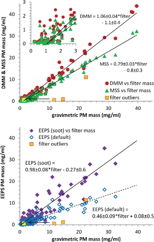
It is apparent in , especially in the inset, that the correlation between instrument and filter deteriorates at low emissions levels, here below about 3 mg/mi. This occurs because of variability in filter PM collection and weighing, a conclusion that is evident in and from the fact that an excellent correlation between instruments extends to well below 1 mg/mi. The problem with the filter method originates from vapor adsorption onto filter media (Chase et al. Citation2004), which contributes to both mass variability and the average bias apparent from the nonzero x-axis intercept in the inset of . The artifact impact on the PM emissions rate scales proportionally with dilution, namely, the CVS flow rate. The 10–20 m3/min flowrates used in the present work () are based on pre-LEV III/Tier 3 practices where dilution ratios are chosen to ensure no water condensation in combined FTP – US06 tests. Consequently, the high exhaust flows encountered during the US06 portion of the test determine the CVS flow rate, which is about three to four times higher than allowed for FTP testing under CFR 40 Part 1066 regulations. Optimizing the CVS flow rate for the FTP drive cycle will reduce the 1.1 ± 0.4 mg/mi intercept (bias) in to about 0.40 ± 0.13 mg/mi (Part 1066 allows a correction for the bias). In addition, it will reduce the variability (x-axis scatter in the inset) from the present ±1.5 mg/mi to about ±0.5 mg/mi, making the filter method practicable for the 3 mg/mi LEV III/Tier 3 standard. PM sampling conditions will remain the same for an optimized CVS flow rate since Part 1066 regulations require the filter face temperature to be maintained at 47 ± 5°C (also, recent work by Jung et al. Citation(2015) shows PM sampling of modern engine exhaust to be relatively insensitive to modest changes in dilution factor and filter face velocity).
Figure 2. Correlations between MSS, DMM, and EEPS measurements of FTP cycle PM mass emissions for the six GDI test vehicles. Inset: Expansion of the 0–3 mg/mi region.
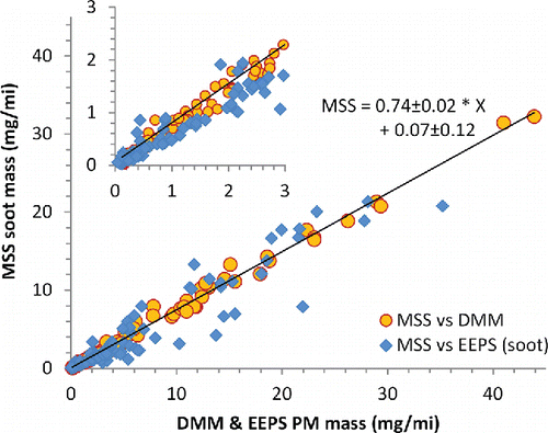
Figure 3. PFI vehicle PM emissions over the FTP drive cycle: correlations between MSS, DMM, and EEPS data.
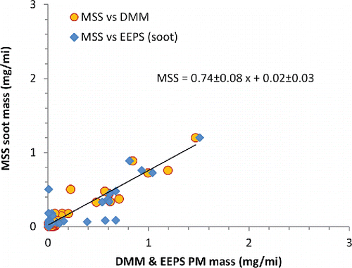
PM emissions from the two PFI test vehicles fall below 2 mg/mi, even during the cold start phase; thus, at the present CVS flow rates the adsorption artifact dominates filter collection of PM and the filter to instrument correlation is effectively zero. However, as demonstrates, the correlation between instruments remains good. The EEPS and DMM exhibit an approximately 1:1 correlation (with a few EEPS outliers), and MSS soot mass measurements exhibit a 0.74 ± 0.08 regression against the DMM and EEPS values. This suggests that the very low PM emissions from PFI engines can remain predominantly soot and supports the similar observations previously reported by Forestieri et al. Citation(2013).
Solid particle number emissions
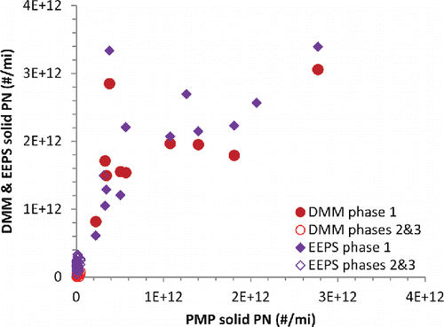
displays the correlations between solid particle number emissions estimated by DMM and EEPS versus the regulatory PMP method over the FTP drive cycle. As with the PM mass measurements above, the data represent emissions rates for individual FTP phases and not the weighted average. For the instruments, we identify solid particles with the accumulation mode. The DMM calculation assumes that the accumulation mode dominates, that the reported geometric mean diameter is representative of this mode, and the geometric standard deviation is 2.05 (Harris and Maricq Citation2001). In the EEPS case, we associate the larger size mode in the bimodal fit with the accumulation mode. In both cases, the 23 nm lower cutpoint is applied assuming a lognormal size distribution.
Figure 4. Phase by phase GDI vehicle solid particle number emissions for the FTP drive cycle. Top panel: Correlation between PMP method and DMM. Bottom panel: Correlation between PMP method and EEPS. Solid symbols represent the soot optimized inversion; open symbols the default inversion.
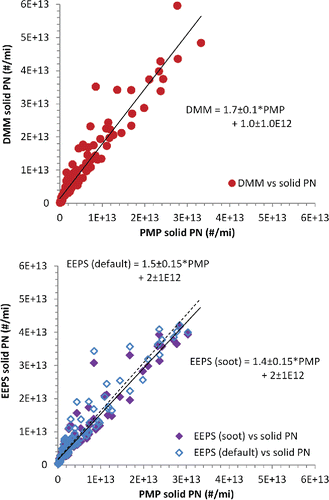
The DMM data plotted in are not derived from the number concentrations reported by the instrument software, which overestimates the PMP solid particle count by an average factor of 2.7. Instead, particle number is calculated from the corona charging efficiency using the total current (mobility plus impactor stages) and the geometric mean diameter measured by the DMM, as described in the SI. This provides closer agreement with the PMP method, with a regression coefficient of 1.7 ± 0.1. The EEPS gives a better estimate of solid number, with a regression slope of 1.4 ± 0.15, but with somewhat higher variability. The EEPS estimate depends only weakly on the choice of inversion algorithm, as the default inversion yields a regression slope of 1.5 ± 0.15.
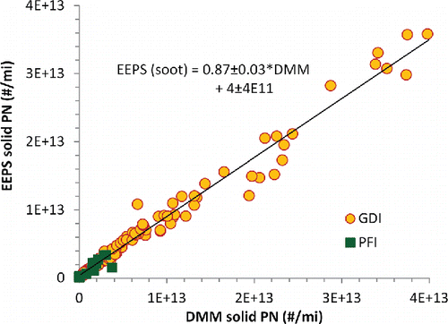
As seen in , solid particle estimates by DMM and EEPS correlate well with each other, better than with the regulatory count method. The regression slope of 0.87 indicates a systematic overestimate of solid number emissions by the DMM relative to the EEPS. This originates from the DMM's inability to distinguish nucleation and accumulation modes; a small nucleation mode presence causes an underestimation of accumulation mode diameter, which raises the particle number calculated from corona charging efficiency (see the SI).
Figure 5. EEPS to DMM correlation of GDI and PFI vehicle phase by phase solid particle number emissions for the FTP drive cycle.
The systematic overestimate by DMM and EEPS relative to the regulatory method is likely due to our use of the accumulation mode as a surrogate for solid particles. There are a few ways that this could lead to an over count. First, evaporation of condensed organic material in the volatile particle remover stipulated by regulations can reduce the size of the remaining soot particles, so that more fall under the 23 nm lower size cutpoint and are not counted. A loss of the 21% semivolatile content indicated by MSS data would reduce particle size approximately 10%, assuming soot particles near 23 nm are compact. But for a GDI accumulation mode with a ∼50 nm geometric mean diameter, the resulting change in particle number above 23 nm is only about 5%. Another possibility is that what we fit as the accumulation mode includes liquid, or mostly liquid, particles in addition to soot. This could be avoided by incorporating a thermodenuder or catalytic stripper upstream of the EEPS, but then the resulting EEPS measurement would underestimate PM mass and would be blind to the presence of a nucleation mode.
The scatter between instruments and the PMP solid particle count deteriorates for PFI vehicles, as seen in ; however, this appears largely because of the difference in axes scales. Phase 2 and 3 emissions rates from the PFI vehicles are very low, below 4 × 10¹¹ particles/mi by all three methods, and essentially uncorrelated. The cold start number emissions remain reasonably well correlated between the DMM and EEPS in , but correlate more poorly with the PMP method in .
EEPS soot versus default inversion
From their literature review, Wang et al. Citation(2016b) found that previous studies on average showed the EEPS to underestimate soot diameter, record narrower size distributions, and overestimate number concentration relative to SMPS and CPC measurements. They developed the EEPS soot inversion by empirical calibration against size selected soot particles from a diesel engine run with 6 ppmw sulfur fuel. compares GDI vehicle transient size distributions recorded with the soot optimized versus original default inversion algorithms. It clearly shows that the major change produced by the soot inversion is a broadening of the accumulation mode. Note, that the GDI exhaust PM size distributions are well described as bimodal lognormal.
Figure 7. EEPS transient size distributions of GDI exhaust PM (vehicle 1) for the cold start phase of the FTP drive cycle. Top panel: Default (original) inversion. Bottom panel: Soot optimized inversion. Traces outlining some of the peaks illustrate bimodal lognormal fits.
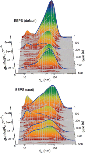
Total number concentration changes only slightly between default and soot inversion, which explains why some earlier comparisons of exhaust particle number measurements found good agreement between EEPS and CPC (Zervas and Dorlhène Citation2006). In , the soot inversion lowers concentration at the center of the distribution and raises it in the wings. Geometric mean diameter remains approximately the same irrespective of which inversion is used, as evident from the vehicle 1 transient size distributions in and in the average cold start diameters across all GDI tests in Figure S2 (in the SI). The roughly factor of 2 increase in PM mass obtained with the soot inversion, which brings the EEPS measurement into good agreement with the gravimetric method in , comes predominantly from the increased accumulation mode width. The average value of σg,a from the soot inversion is about 20% larger than with the default inversion (see Figure S3 in the SI), where the average is calculated by number weighting the second by second GSD over each FTP test phase. Thus, the soot inversion brings the uncharacteristically low GSD of about 1.7 provided by the default inversion to a GSD of near 2.1, in close agreement previous PM measurements from gasoline direct injection engines (Harris and Maricq Citation2001).
Discussion and conclusions
Overall, the DMM and EEPS performed well in measuring PM mass emissions, both relative to the regulatory method and to each other. The DMM reproduced gravimetric PM mass with an average regression slope of 1.06 ± 0.04 over the six GDI vehicles, significantly better than the overestimates of up to 39% reported in earlier comparisons (Kittelson et al. Citation2006; Mamakos et al. Citation2006). Using the optimized soot inversion, the EEPS estimated PM mass with an average regression of 0.98 ± 0.08. This is a factor of two better than with the original default inversion, confirming that the published calibration with diesel soot extends to GDI vehicles (Xue et al. Citation2015; Wang et al. Citation2016b).
For individual measurements the variability between instrument and gravimetric method is higher than indicated by the regression slope uncertainties, since these represent an error in the mean. At emissions rates above 3 mg/mi, considered the lower limit of filter method reliability in the present work owing to use of overly high CVS flowrates, the average relative difference in mass, |ΔM|/Mfilter, is 14% for the DMM and 40% for the EEPS versus gravimetric. Reasons for improvement in DMM performance over the previous work is not entirely clear. Partly this could arise from the sheath air added to protect the corona wire. Another factor could be cleanliness of the impactor rods. We have noticed that as these collect soot, which lowers their aerodynamic cutpoints, they overestimate size and, hence, mass. To mitigate this, we routinely monitor the mass to total current ratio as an indicator that cleaning might be necessary. At 14% average deviation, the DMM is useful for engine and exhaust aftertreatment development, given the advantages of second by second emissions data. The 40% average EEPS deviation at least partly arises from extracting six second by second parameters from the transient size distributions, and there may potentially remain a contribution from PM differences between the present GDI vehicles and the diesel engine used for EEPS calibration. Still, the additional size information provided by the EEPS makes it a useful tool, particularly in detecting the appearance of a nucleation mode.
Both DMM and EEPS provide respectable estimates of solid particle emissions above 23 nm, with regression slopes of 1.7 ± 0.1 and 1.4 ± 0.2, respectively, relative to the PMP method. The higher variability in number measurement as compared to PM mass seems counterintuitive, but may derive from both instruments' reliance on corona charging of the particles. Charging efficiency increases with particle size as dm1.3 (see the SI); thus, particle number scales as Itot dm−1.3, where Itot represents the total current for either the DMM or EEPS. The calculation of mass incurs an additional factor of dm2.3 to account for particle effective density, yielding a net scaling of mass as Itot dm1. Consequently, the determination of mass exhibits a lower dependence on particle size than the measurement of number for both DMM and EEPS. This may partly explain the better estimation of mass emissions. The other likely contributor, discussed above, is that for solid number count the instruments separate solid from total particles by size, whereas the PMP method does this by evaporation (Giechaskiel et al. Citation2012).
A positive outcome in the present study is the consistency between instruments. Mass estimations from EEPS and DMM agree well to below 1 mg/mi, although there are some outliers in the EEPS estimates at very low emissions levels. The number correlation between EEPS and DMM is better than with the PMP solid count, likely because both rely on size to distinguish solid particles. The MSS measurement of soot mass exhibits consistent regression slopes of 0.79 ± 0.03, 0.74 ± 0.02, 0.74 ± 0.08, respectively, against gravimetric mass for GDI vehicles, DMM and EEPS mass for GDI vehicles, and DMM and EEPS mass for PFI vehicles. This is consistent with other recent work on the soot fraction of gasoline vehicle PM (Khalek et al. Citation2010; Forestieri et al. Citation2013) indicating that it remains relatively high even as emissions levels decrease. A potential explanation for this is that gaseous emissions regulations are also becoming more stringent, leading to reduced semivolatile PM precursor concentrations.
Our experience over this two plus year study period suggests that these instruments are usable in routine emissions testing applications. Their maintenance requirements are comparable to other conventional emissions analyzers, such as chemiluminescence NOx detectors. We used no special setup/calibration procedures and did not require major service. There are two major differences between these PM instruments and conventional gaseous emissions analyzers. First, gaseous analyzers can use inlet filters to reduce contamination; obviously PM instruments cannot. Second, gaseous analyzers can be spanned by reference gases, which is a good indicator of proper performance. Such a reference is nonexistent for PM, which necessitates more vigilant maintenance to ensure good performance.
While not examined here, one can anticipate that with an equivalent soot inversion algorithm, the DMS500 can also provide comparable measurement capabilities. Likewise, the results of this work should extend to other drive cycles, such as the New European Drive Cycle, the Unified Cycle, and most of the new Worldwide harmonized Light vehicles Test Procedures (WLTP) Cycle, as well as to on-road emissions measurements with portable emissions measurement systems (Rubino et al. Citation2009). The US06 portion of the Supplemental FTP and likely the high speed portion of the WLTP test are notable exceptions to generalizing the present results. These drive cycles incur very high exhaust temperatures that impact PM measurements in ways not evident in the FTP tests presented here, a subject that will be examined in a future article.
PM_inst_comp_supplemental_info.docx
Download MS Word (261.5 KB)Acknowledgments
The authors thank John Roth and Jim Pakko for providing and caring for some of the test vehicles used in this work.
References
- Awasthi, A., Wu, B. S., Liu, C. N., Chen, C. W., Uang, S. N., and Tsai, C. J. (2013). The Effect of Nanoparticle Morphology on the Measurement Accuracy of Mobility Particle Sizers. MAPAN, 28:205–215.
- Bougher, T. L., Khalek, I. A., Laroo, C. A., and Bishnu, D. K. (2012). Determination of the PEMS Measurement Allowance for PM Emissions Regulated Under the Heavy-Duty Diesel Engine in-Use Testing Program. SAE Technical Paper 2012-01-1250.
- California Air Resources Board (2015). Amendments to the Low-Emission Vehicle Program – LEV III. Available at http://www.arb.ca.gov/msprog/levprog/leviii/leviii.htm
- Cavina, N., Poggio, L., Bedogni, F., Rossi, V., and Stronati, L. (2013). Benchmark Comparison of Commercially Available Systems for Particle Number Measurement. SAE Technical Paper 2013-24-0182.
- Chase, R. E., Duszkiewicz, G. J., Richert, J. F. O., Lewis, D., Maricq, M. M., and Xu, N. (2004). PM Measurement Artifact: Organic Vapor Deposition on Different Filter Media. SAE Technical Paper 2004-01-0967.
- Environmental Protection Agency (2015). Code of Federal Regulations, Title 40: Protection of Environment, Part 1066: Vehicle-Testing Procedures. Available at http://cfr.regstoday.com/40cfr1066.aspx
- Forestieri, S. D., Collier, S., Kuwayama, T., Zhang, Q., Kleeman, M. J., and Cappa, C. D. (2013). Real-Time Black Carbon Emission Factor Measurements From Light Duty Vehicles. Environ. Sci. Technol., 47:13104–13112.
- Giechaskiel, B., Mamakos, A., Andersson, J., Dilara, P., Martini, G., Schindler, W., and Bergmann, A. (2012). Measurement of Automotive Non-Volatile Particle Number Emissions Within the European Legislative Framework: A Review. Aerosol Sci. Technol., 46:719–749.
- Harris, S. J., and Maricq, M. M. (2001). Signature Size Distributions for Diesel and Gasoline Engine Exhaust Particulate Matter. J. Aerosol Sci., 32:749–764.
- Johnson, T., Caldow, R., Poecher, A., Mirme, A., and Kittelson, D. (2004). A New Electrical Mobility Particle Sizer Spectrometer for Engine Exhaust Particle Measurements. SAE Technical Paper 2004-01-1341.
- Jung, H., Johnson, K. C., Russell, R. L., Durbin, T. D., Miller, W., Xue, E. J., Swanson, J., and Kittelson, D. (2015). Very Low PM Mass Measurements. Coordinating Research Council Project E-99. Available at http://www.crcao.org/reports / recentstudies2015 / E-99/CRC_ARB%20Final%20Report_E-99_v15d%20REVISED%202015_09_25.pdf
- Keskinen, J. and Rönkkö, T. (2010). Can Real-World Diesel Exhaust Particle Size Distribution be Reproduced in the Laboratory? A Critical Review. J. Air Waste Manage. Assoc., 60:1245–1255.
- Khalek, I. A., Bougher, T., and Jetter, J. J. (2010). Particle Emissions From a 2009 Gasoline Direct Injection Engine Using Different Commercially Available Fuels. SAE Technical Paper 2010-01-2117.
- Khalek, I. A., Kittelson, D. B. and Brear, F. (2000). Nanoparticle Growth During Dilution and Cooling of Diesel Exhaust: Experimental Investigation and Theoretical Assessment. SAE Technical Paper 2000-01-0515.
- Khan, M. Y., Johnson, K. C., Durbin, T. D., Jung, H., Cocker, D. R., Bishnu, D., and Giannelli, R. (2012). Characterization of PM-PEMS for in-Use Measurements Conducted During Validation Testing for the PM-PEMS Measurement Allowance Program. Atmos. Environ., 55:311–318.
- Kittelson, D., Hands, T., Nickolaus, C., Collings, N., Niemela, V., and Twigg, M. (2006). Mass Correlation of Engine Emissions with Spectral Instruments. Trans. Soc. Automot. Eng. Jpn, 37:67.
- Lehmann, U., Niemelä, V., and Mohr, M. (2004). New Method for Time-Resolved Diesel Engine Exhaust Particle Mass Measurement. Environ. Sci. Technol., 38:5704–5711.
- Mamakos, A., Ntziachristos, L., and Samaras, Z. (2006). Evaluation of the Dekati Mass Monitor for the Measurement of Exhaust Particle Mass Emissions. Environ. Sci. Technol., 40:4739–4745.
- Maricq, M. M. (2014). Examining the Relationship Between Black Carbon and Soot in Flames and Engine Exhaust. Aerosol Sci. Technol., 48:620–629.
- Maricq, M. M., Podsiadlik, D. H., and Chase, R. E. (1999). Examination of the Size Resolved and Transient Nature of Particle Emissions From Motor Vehicles. Environ. Sci. Technol., 33:1618–1626.
- Maricq, M. M. and Xu, N. (2004), The Effective Density and Fractal Dimension of Soot Particles From Premixed Flames and Motor Vehicle Exhaust. J. Aerosol Sci., 35:1251–1274.
- Marjamäki, M., Keskinen, J., Chen, D.-R., and Pui, D. Y. H. (2000). Performance Evaluation of the Electrical Low-Pressure Impactor (ELPI). J. Aerosol Sci., 31:249–261.
- Mirme, A., Noppel, M., Peil, I., Salm, J., Tamm, E., and Tammet, H. (1984). Multi-Channel Electric Aerosol Spectrometer, in Intern. Comm. for Cloud Phys. 11th Intern. Conf. on Atmosphere Aerosols, Condensation and Ice Nuclei, (SEE N85–32596 21–47), Vol. 2, pp. 155–159.
- Olfert, J. S., Symonds, J. P. R., and Collings, N. (2007). The Effective Density and Fractal Dimension of Particles Emitted from a Light-Duty Diesel Vehicle with a Diesel Oxidation Catalyst, J. Aerosol Sci., 38:69–82.
- Park, K., Cao, F., Kittelson, D. B., and McMurry, P. H. (2003). Relationship Between Particle Mass and Mobility for Diesel Exhaust Particles. Environ. Sci. Technol., 37:577–583.
- Peckham, M. S., Finch, A., Campbell, B., Price, P., and Davies, M. T. (2011). Study of Particle Number Emissions from a Turbocharged Gasoline Direct Injection (GDI) Engine Including Data from a Fast-Response Particle Size Spectrometer. SAE Technical Paper 2011-01-1224.
- Petzold, A., Marsh, R., Johnson, M., Miller, M., Sevcenco, Y., Delhaye, D., Ibrahim, A., Williams, P., Bauer, H., Crayford, A., Bachalo, W. D. and Raper, D. (2011). Evaluation of Methods for Measuring Particulate Matter Emissions from Gas Turbines. Environ. Sci. Technol., 45:3562–3568.
- Petzold, A., Ogren, J. A., Fiebig, M., Laj, P., Li, S.-M., Baltensperger, U., Holzer-Popp, T., Kinne, S., Pappalardo, G., Sugimoto, N., Wehrli, C., Wiedensohler, A. and Zhang, X.-Y. (2013). Recommendations for Reporting “Black Carbon” Measurements. Atmos. Chem. Phys., 13:8365–8379.
- Price, P., Stone, R., Collier, T., Davies, M., and Scheer, V. (2006). Dynamic Particulate Measurements From a DISI Vehicle: A Comparison of DMS500, ELPI, CPC and PASS. SAE Technical Paper 2006-01-1077.
- Reavell, K., Hands, T., and Collings, N. (2002). A Fast Response Particulate Spectrometer for Combustion Aerosols. SAE Technical Paper 2002–01-2714.
- Rubino, L., Bonnel, P., Carriero, M., and Krasenbrink, A. (2009). Portable Emission Measurement System (PEMS) for Heavy Duty Diesel Vehicle PM Measurement: The European PM PEMS Program. SAE Technical Paper 2009-24-0149.
- Sardar, S. B., Zhang, S., Larsen, L., Chang, M.-C. O., and McMahon, W. (2015). Evaluation of PM Measurement Precision and the Equivalency of the Single Filter and 3 Filter Sampling Methods in LEV III, 25'th CRC Real World Emissions Workshop, Long Beach.
- Schindler, W., Haisch, C., Beck, H. A., Niessner, R., Jacob, E., and Rothe, D. (2004). A Photoacoustic Sensor System for Time Resolved Quantification of Diesel Soot Emissions. SAE Technical Paper 2004-01-0968.
- Shin, W. G., Wang, J., Mertler, M., Sachweh, B., Fissan, H., and Pui, D. Y. H. (2010). The Effect of Particle Morphology on Unipolar Diffusion Charging of Nanoparticle Agglomerates in the Transition Regime. J. Aerosol Sci., 41:975–986.
- Snelling, D. R., Smallwood, G. J., Liu, F., Gülder, Ö. L., and Bachalo, W. D. (2005). A Calibration-Independent Laser-Induced Incandescence Technique for Soot Measurement by Detecting Absolute Light Intensity. Appl. Optics, 44:6773–6785.
- Symonds, J. P. R., Reavell, K. St. J., Olfert, J. S., Campbell, B. W., and Swift, S. J. (2007). Diesel Soot Mass Calculation in Real-Time with a Differential Mobility Spectrometer. J. Aerosol Sci., 38:52–68.
- Tammet, H., Mirme, A., and Tamm, E. (2002). Electrical Aerosol Spectrometer of Tartu University. Atmos. Res., 62:315–324.
- UN/ECE Regulation 83. (2011). United Nations – Economic Commissions for Europe, Regulation no. 83, Revision 4, 26 April 2011, Uniform provisions concerning the approval of vehicles with regard to the emissions of pollutants according to engine fuel requirements.
- Wang, X. L., Grose, M. A., Avenido, A., Stolzenburg, M. R., Caldow, R., Osmondson, B. L., Chow, J. C., and Watson, J. G. (2016a). Improvement of Engine Exhaust Particle Sizer (EEPS) Size Distribution Measurement - I. Algorithm and Applications to Compact Aerosols. J. Aerosol Sci., 92:95–108.
- Wang, X. L., Grose, M. A., Caldow, R., Osmondson, B. L., Swanson, J. J., Chow, J. C., Watson, J. G., Kittelson, D. B., Li, Y., Xue, J., Jung, H., and Hu, S. (2016b). Improvement of Engine Exhaust Particle Sizer (EEPS) Size Distribution Measurement – II. Engine Exhaust Aerosols. J. Aerosol Sci., 92:83–94.
- Xue, J., Li, Y., Wang, X., Durbin, T. D., Johnson, K. C., Karavalakis, G., Asa-Awuku, A., Villela, M., Quiros, D., Hu, S., Huai, T., Ayala, A., and Jung, H. (2015). Comparison of Vehicle Exhaust Particle Size Distributions Measured by SMPS and EEPS During Steady-State Conditions. Aerosol Sci. Technol., 49:984–996.
- Zervas, E., and Dorlhène, P. (2006). Comparison of Exhaust Particle Number Measured by EEPS, CPC, and ELPI. Aerosol Sci. Technol., 40:977–984.

