ABSTRACT
Wall losses of condensable organic vapors are a significant complication for smog-chamber experiments designed to constrain production of Secondary Organic Aerosols (SOA). Here we develop a dynamical mass-balance model based on the Volatility Basis Set (VBS) to explore various pathways for mass transfer between the bulk of a smog-chamber volume (the vapors and suspended particles) and reservoirs near the chamber walls (deposited and/or nucleated particles on the walls, adsorption to the walls, and sorption into Teflon walls). We consider various limiting cases and explore the sensitivity of inferred SOA yields to assumptions about the actual parameters in a given SOA experiment. We also present data suggesting that adsorptive uptake to Teflon for typical SOA is modest. Broadly, we find that walls become a sink for condensable vapors when those vapors interact with either deposited particles of the Teflon walls, with qualitatively similar effects on the suspended particles. Finally, we show that having a relatively high seed condensation sink is vital to reliable chamber mass balances.
Copyright © 2016 American Association for Aerosol Research
EDITOR:
1. Introduction
Studies of secondary organic aerosol (SOA) formation are mass balances, and so careful consideration of all mass reservoirs and the balance equations connecting them is essential. The SOA mass yield is defined as the mass concentration of formed SOA divided by the mass concentration of consumed precursor (Paulson et al. Citation1990; Kroll and Seinfeld Citation2008); however, it is often conceived as the mass of formed SOA in an ideal context where condensation to suspended particles is the only possible fate of condensable vapors. To determine the SOA mass yield one must measure the loss of a precursor molecule from the gas phase (by reaction with an oxidant) and the corresponding production of condensable product vapors. In almost all cases these condensable products have been inferred based on the appearance of suspended particle mass (SOA mass) formed from the precursor. SOA formation experiments are often carried out in smog chambers (Paulson et al. Citation1990; Cocker et al. Citation2001; Kalberer et al. Citation2004; Tolocka et al. Citation2004; Kroll and Seinfeld Citation2008). The Carnegie Mellon University (CMU) chambers—7–12 m3 Teflon bags (Hartz et al. Citation2005; Stanier et al. Citation2007; Hennigan et al. Citation2011)—are typical; however, chambers range in volume between 1 m3 (Burkholder et al. Citation2007) and 250 m3(Karl et al. Citation2004), and while they are often composed of Teflon, aluminum (Saathoff et al. Citation2009), stainless steel (Kirkby et al. Citation2011), and glass (Koch et al. Citation2000) chambers exist as well. Here we shall focus on Teflon chambers.
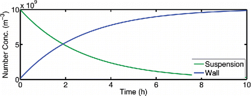
Because chambers have walls, SOA yield calculations must account for losses, including particle losses to walls, vapor losses to walls, and outflow. Prior to precursor oxidation in an SOA formation experiment, a smog chamber is often “seeded” with suspended, inorganic particles as a condensation sink, but “nucleation” experiments are also conducted without intentionally added seeds (Kroll and Seinfeld Citation2005). Our focus here is on Teflon chambers similar to the CMU chambers. Because empirical studies have established that experiments conducted with inert condensation seeds appear to give more reliable results than nucleation experiments for SOA yield mass balances (Cocker et al. Citation2001; Kroll and Seinfeld Citation2005; Pathak et al. Citation2008), we shall consider a typical seeded experiment as a base case. Specifically, we shall assume a base-case particle wall-loss rate constant of 10−4 s−1 (giving a wall-loss timescale of 2.8 h), which is typical for the CMU chamber. Here we shall not address size-dependent wall losses or electrostatic effects, which are other vexing issues that do not directly affect our conclusions (Pierce et al. Citation2008). Over time, the suspended particles deposit to the wall. shows the calculated particle concentration over time in a typical experiment under these conditions (we converted the wall concentrations from # m−2 to an effective volume concentration via the chamber volume to surface area ratio, V:S). After ∼2 h, the aerosol particles reside predominantly on the chamber walls. Nearly all reported SOA mass yields are corrected to account for particle deposition (Paulson et al. Citation1990; Stanier et al. Citation2007).
Figure 1. An example of particle number losses in a typical SOA chamber experiment with negligible coagulation and a particle loss frequency of 0.36 h−1 (10−4 s−1). Suspended particles are deposited to the wall over time.
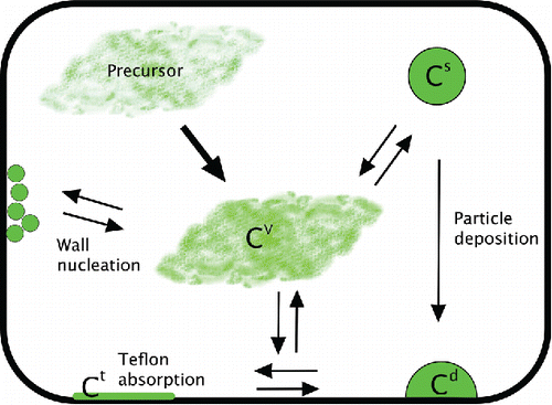
Interaction of vapors with chamber walls is another key element in the chamber mass balance. In most SOA formation experiments, these losses are essentially unconstrained; neither the gas-phase SOA vapors nor any constituents on the walls are routinely measured directly. This is because no technique is known to measure the organics on the walls and the very low vapor pressure (10−7–10−5 torr) molecules are quite difficult to measure in the gas phase. Only within the past few years has chemical ionization mass spectrometry achieved the sensitivity to measure some of the condensable organic species (Ehn et al. Citation2014; Trostl et al. Citation2016) and even so comprehensive, calibrated measurements remain elusive. Further, a full consideration of vapor-wall interaction would require the description of multiple proposed (and often poorly constrained) processes. To date at least three possible interaction pathways between vapors and chamber walls have been proposed: condensation of vapors to particles deposited to the chamber wall (and potentially evaporation from those particles) (Weitkamp et al. Citation2007; Hildebrandt et al. Citation2009); sorption of vapors to the wall material (adsorption or absorption, again possibly reversible) (Matsunaga and Ziemann Citation2010; Zhang et al. Citation2015; Krechmer et al. Citation2016); and nucleation of new particles on the walls (Pathak et al. Citation2008). We show a schematic showing the mass balance for an SOA experiment including these wall interactions in .
Figure 2. Wall interactions in an SOA formation experiment. Many wall-loss processes complicate the determination of the SOA mass yield, which is based on suspended particle concentration (Cs). Particles deposit to chamber walls, and these particles may interact with the vapor phase. Organic vapors may also be lost to the wall directly via Teflon absorption and/or wall nucleation.
While the full influence of the walls is unconstrained, there is direct experimental evidence of vapor-wall interactions. For example, Pathak et al. demonstrated that chamber walls act as a sink for SOA vapors and that this sink greatly influences apparent SOA yields (Pathak et al. Citation2007; Pathak et al. Citation2008), Kroll considered the “induction” effect leading to lower observed SOA yields in nucleation than seeded SOA experiments (Kroll and Seinfeld Citation2005), and Stanier et al. presented evidence that the walls can act as a source of vapors upon heating and a sink upon cooling (Stanier et al. Citation2007). More recently, Matsunaga et al. showed that organic vapors can be lost to Teflon walls even at sub-saturated conditions (Matsunaga and Ziemann Citation2010), and these interactions of vapors with the Teflon directly have garnered significant attention (McVay et al. Citation2014; Yeh and Ziemann Citation2014; Zhang et al. Citation2014).
The first goal of this study is to assess the likely influences of vapor-wall interactions on observed SOA production levels. We assess the importance of wall-loss processes relative to key experimental timescales, such as the timescale for precursor oxidation and the timescale for condensation onto suspended particles. Further, we suggest strategies to minimize the influences of these effects. Finally, to gain insight regarding which parameters are most important to constrain, we investigate the sensitivity of the model predictions to poorly known parameters such as the particle mass accommodation coefficient, the corresponding accommodation coefficient to Teflon, and the eddy diffusivity coefficient of the chamber (which governs the wall interaction timescales).
We develop a dynamic model for smog-chamber experiments based on mass and flux balances. The model ties vapor-wall interactions together with vapor-phase production, condensation onto suspended particles, particle deposition, and heterogeneous nucleation on the walls. The base model addresses particle deposition and the interaction of vapors with the deposited aerosol particles. Subsequently, we consider the potential influences of sorption to Teflon and wall nucleation on observed aerosol mass yields.
We present the flux to deposited particles as the base case for historical reasons; we have analyzed SOA formation experiments considering this scenario for many years. Specifically, we have assumed that vapor fluxes to the chamber walls were associated only with fluxes to and from particles that had deposited to those walls, and that the vapor flux toward the walls could be bounded by two limiting cases: (1) the flux to particles deposited on the walls is identical to the flux to suspended particles; or (2) there is no flux at all to particles deposited on the walls (Weitkamp et al. Citation2007; Hildebrandt et al. Citation2009). In practice, we have defined a parameter, ω, which is the ratio of the flux to a unit surface area of particles in suspension versus a unit surface area of particles deposited to the walls. The two limiting cases correspond to ω = 1 and ω = 0.
The fundamental issue associated with vapor wall loss is diffusion. Even in a turbulently mixed chamber, diffusion through a boundary layer near the wall will take a certain amount of time. If condensable vapors are lost near or at the wall for any reason a concentration gradient will develop in the boundary layer that will quickly become rate limiting for mass transfer (McMurry and Grosjean Citation1985).
The model described in this article is built around the basic assumption that condensable vapors in a chamber can go to one of two places: to the suspended particles or toward the wall (we neglect outflow, which is a minor term in the collapsible chambers employed at CMU). Once headed toward the wall, the vapors will then be distributed among several possible reservoirs: particles deposited on the walls; particles nucleated on the walls; the interface (adsorption); or into the wall material (absorption). Several critical parameters dictate whether condensation to suspended particles or condensation to the wall dominates the dynamics in the chamber, but the most important is the ratio of two collision frequencies: the collision frequency of vapors with suspended particles, and the collision frequency of vapors with anything near the wall. In general, when this ratio is large (vapors interact with suspended particles before the walls), data interpretation is relatively straightforward, but, when it is small (vapors interact with the walls before the suspended particles) data interpretation gets more difficult. However, a second critical parameter for each surface (particles and the wall region) is the accommodation coefficient: the fraction of collisions that result in uptake. When accommodation coefficients are factored in the collision frequencies become condensation sinks. This is uncertain and debated for each reservoir, but once mass accommodation coefficients are factored in, the resulting ratio of condensation sinks for the suspended particles and the walls fully defines the behavior of the chamber.
2. Treatment of wall-deposited particles
When vapors diffuse to the near-wall region (for the sake of argument to within a micron or so of the wall), it remains an open question whether they are more strongly influenced by the wall material itself (Teflon in this case) or by any particles that have deposited on the walls. Condensation onto wall-deposited particles could be an important factor leading to vapor loss, and because we have considered that effect in many previous publications we shall treat it first. The critical questions are: what happens to deposited particles once they strike the walls; and then, if they survive, how does the presence of particles on the walls (rather than in suspension) influence the rate of mass transfer to those wall-deposited particles. It is likely that the particles would remain coherent and not completely vanish for at least some time after adhering to the Teflon, as most organics have very high contact angles with Teflon (Li et al. Citation1993). For the sake of this discussion, we shall assume that typical chamber cleaning (heating and UV illumination) is effective and produces an initial condition at the beginning of each experiment with no particles on completely clean Teflon walls.
An important additional constraint exists for semi-volatile mixtures. Mixtures are only at equilibrium when the composition of each particle (each condensed-phase reservoir) is the same, or more strictly when the activity of each constituent in each phase of every reservoir is the same. Consequently, whether or not there are mass-transfer limitations to wall-deposited particles, particle equilibration will influence the chamber mass balance and thus the apparent SOA yields. Here the results depend substantially on whether other processes occur near the walls. If, for example, vapors also sorb to the Teflon walls with high efficiency, a strong concentration gradient may always exist between the chamber and the walls. In this case there will be no up-gradient return flux to the bulk of the chamber. However, one limiting case involves efficient accommodation to relatively abundant particles on the walls and more limited accommodation to the Teflon itself, and that is where we shall start.
Given the significant uncertainties and the fact that we are addressing couplings between two unmeasured reservoirs, simplified empirical corrections for wall deposition have been used in the past. Weitkamp et al. Citation(2007) corrected for the interaction of vapors with wall-deposited particles and proposed an interaction parameter, ω. This parameter relates the flux to a wall-deposited particle and what the flux would be if the same particle were still in suspension. Two limiting cases are easy to understand: if ω = 1, wall-deposited particles behave exactly like suspended particles, while if ω = 0, wall-deposited particles effectively leave the system and receive no further flux from the gas phase (and there is no other vapor wall loss). Weitkamp et al. Citation(2007) used analyses based on these assumptions to determine the uncertainty range for SOA production in their experiments. Hildebrandt et al. Citation(2009) used a similar bounding approach and showed that the wall-interaction assumption has a strong influence on calculated mass yields, particularly when chemistry is slow (as in the photo-oxidation of toluene where τrxn∼ 1 day).
To illustrate these effects, we show in a simple simulation of α-pinene ozonolysis, using the dynamical Volatility Basis Set (VBS) with a subset of the semi-volatile yields presented by Trump (Trump et al. Citation2014; Trump and Donahue Citation2014). We include three VBS bins, C* = [0.01, 1, 10] µg m−3, with mass yields y = [.004, .051, .086]. The great majority of the SOA is thus semi-volatile, consistent with “traditional” interpretation based on equilibrium partitioning (Odum et al. Citation1996; Presto and Donahue Citation2006) but we treat the condensation and evaporation dynamically, based on the time-dependent activity differences between various reservoirs (Trump and Donahue Citation2014). This subset encompasses all of the key features we seek to examine, simulating reasonably low-loading experiments, and by focusing on the “traditional” yields we both put the problem in historical context and maximize the simulated interactions with the walls. Aerosols with a much higher fraction of extremely low volatility material (Ehn et al. Citation2014) would have a correspondingly lower activity of semi-volatile material in the suspended particles and thus less significant interactions between semi-volatile vapors and reservoirs near the chamber walls (Matsunaga and Ziemann Citation2010).
Figure 3. Uncertainty ranges for total SOA formed (shown in grey) when an equivalent amount of condensable vapors (ozonolysis of 40 ppbv α-pinene) is produced with either (a) fast or (b) slow chemistry. The range is bound by the ω = 1 and ω = 0 empirical scaling factors.
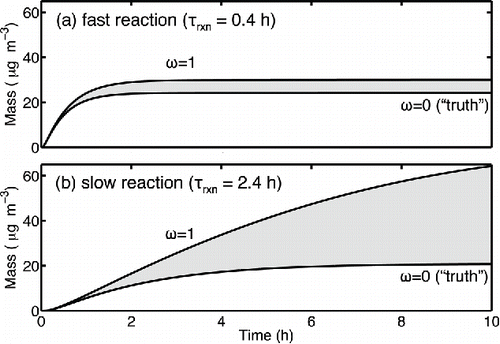
We simulate fast and slow oxidation in a chamber initially containing 40 ppbv (226 µg m−3) of α-pinene, which, using these model parameters, would produce about 26 µg m−3 of SOA (a mass yield of 0.11) in an ideal experiment without wall losses. For the base case we assume an initial seed concentration of 1010 # m−3 (104 cm−3) of 200 nm diameter particles, giving a condensation sink of 180 h−1 (5·10−2 s−1). For this example, we allow the condensable vapors to condense only to the suspended particles, but then “correct” the results to account for SOA that might have condensed to particles already deposited on the walls. Thus, in this case the ω = 0 case is accurate (“truth”) while the ω = 1 case infers condensation that did not actually occur and thus over-estimates the real SOA production. When gas-phase chemistry is fast (0.4 h) relative to the 2.8 h particle loss timescale (), the aerosol mass production is tightly constrained by the two limiting cases. Specifically, the potential error is given by the ratio of the chemical and wall-loss timescales (0.4 h / 2.8 h = 0.14); there is a roughly 15% difference between the two cases. However, for slower chemistry, the wall-loss uncertainty is overwhelming—SOA continues to be formed long after the majority of the particles are deposited onto the wall (). For τrxn= 2.4 h, the method of Weitkamp et al. indicates a wide uncertainty range for the total SOA production: the ω = 1 analysis indicates up to 300% more SOA than the ω = 0 analysis (). The error grows dramatically because observed mass yields tend to rise steeply with increasing SOA mass (Presto and Donahue Citation2006). With the semi-volatile distribution in this simulation, significant condensation continues even in the final stages of α-pinene oxidation when most of the particles are on the chamber walls; thus increases in the suspended mass during the final 2 h get multiplied by a large factor.
While the ω = 1 and ω = 0 cases appear to bound possible wall interactions, we would like a more firmly grounded method. This could help to further constrain SOA yields when formation chemistry is slow. Furthermore, because particle composition typically changes with time, the ω = 0 case does not allow particle compositions to equilibrate and thus cannot constitute a fully consistent treatment. It also implicitly assumes that no vapors are lost to the walls, which we know is almost certainly incorrect.
3. Model description
We calculate a dynamic concentration balance for each chemical species i involved in a smog-chamber experiment with respect to different reservoirs (each indicated with a superscript). We use a volatility basis set (VBS) approach to describe the organics (organics within a C* “bin” are treated as a lumped chemical species) (Donahue et al. Citation2006; Trump and Donahue Citation2014). We consider the vapor (superscript v) and particulate-phase concentrations separately, and the suspended (superscript s) and we treat the suspended and wall-deposited (superscript d) particles as distinct populations. Material can also reside near the walls (superscript w) and in the Teflon (superscript t). The model accounts for production in various reservoirs (Pri), net transport to or from each particle population ( meaning a net flux from r to q), including mass transfer due to particle deposition (
), which is governed by a number-loss rate constant kw. We track the mass concentrations in all reservoirs (
) as well as the number concentrations (Ns, Nd) for each particle population. All of the concentrations are bulk averages, and so the particle populations are implicitly homogeneous; at this level of approximation it is appropriate to consider monodisperse particles with diameter
, which we calculate based on the mass per particle and average particle density. The balance equations in the model are:
[1]
[2]
[3]
[4]
[5]
[6]
[7]
In this version of the model, we do not explicitly track the vapor concentration near the chamber wall () but rather assume a flux balance as shown in Equation (Equation7
[7] ). This flux balance is reasonable because the volume of the wall region is defined by the height of deposited particles and a general roughness scale height (of order µm) and so the volume is negligible compared the bulk chamber volume. The fluxes in Equation (Equation7
[7] ) will thus be large compared to the total mass loading and the equilibration timescale for the near-wall vapors will be exceedingly short.
We specify the vapor production term, , as needed in the model, but in general we simulate first-order loss of a precursor to form condensable products, distributed in volatility bins of a VBS (Donahue et al. Citation2006). Particle-phase production can be included (Trump and Donahue Citation2014) but here we assume
. While there might be some interesting interactions between, for example, reversible condensed-phase oligomerization reactions and vapor-wall deposition, we are interested in exploring the effects of vapor deposition and to introduce multiple poorly constrained effects simultaneously would be more confusing than illuminating.
The flux of species i from the vapor phase to the suspended-particle population is:[8]
where is the collision frequency of molecule i with the suspended particles,
is an effective accommodation coefficient, and the term in parentheses is the thermodynamic driving force for condensation, in which
is the mass fraction in the suspended particles, K is a Kelvin term, and
is the saturation concentration, including any activity coefficient.
The collision frequency is proportional to the surface area concentration () and the mean speed of the molecule perpendicular to the surface
:
[9]
For extremely small particles (dp ⪅ 10 nm) one must consider the finite size of the condensing molecule as well as the reduced mass of the collision (and not just the molecular speed (Trostl et al. Citation2016), but here we neglect these effects because we only consider seeded experiments. The term is a Fuchs-like correction factor for diffusion limitations to particles close to or larger than the mean free path (with small Knudsen number):
[10]
The collision frequency is given by setting αi = 1, while the effective mass accommodation coefficient will be somewhat larger than the actual mass accommodation coefficient for larger particles where diffusion can become rate-limiting to mass transfer. Qualitatively, it is the fraction of molecules that accommodate to the surface after diffusing to near the particle surface—when diffusion is rate limiting a molecule near a surface will collide with that surface many times before diffusing away.[11]
We separate the terms in this way because the collision frequency of vapors with the particle surface (especially compared with the collision frequency of vapors with the chamber walls) is a critical term in chamber experiments. The suspended-particle condensation sink is a first-order rate constant, and it defines the equilibration timescale between the vapor and suspended particle phases (Saleh et al. Citation2013):[12]
The thermodynamic driving force for condensation is the difference between the bulk gas-phase concentration and the equilibrium concentration over the suspended particles, . For these simulations all particles will be sufficiently large (
nm) so that the Kelvin term is insignificant (K ≃ 1). We shall also assume “pseudo” ideal solutions so that
remains constant. Finally we assume that the suspended (and deposited) particles are well mixed, so that the bulk suspended mass-fraction of species i gives its surface concentration, which in turn is what drives the instantaneous net flux to the particles,
. We thus do not consider diffusion limitations within particles within particles in this work.
The flux of species i from the suspended-particle population to the wall-deposited particle population is:[13]
The flux of species i from the bulk chamber vapor phase to the near-wall region as well as the fluxes from the near-wall region to either the deposited particles or the Teflon walls are the major topic of this work. Approximations to infer this flux have evolved over time, and we shall consider several of them.
3.1. Vapor-phase condensation to chamber walls
The premise behind the vapor wall-loss corrections described in Section 2 is that the mass flux per particle to deposited particles will be proportional to the mass flux per particle to the suspended particles, with an additional term ω. The original term ω is empirical, but we can operationally define a very similar term:[14]
The term ω deviates from unity when the surface area of a deposited particle differs from the suspended particle or when the near-surface vapor concentration differs from the bulk vapor concentration. We use ω for historical reasons, as published wall-loss corrections have been based on the assumption that this multiplier bounds the wall-loss corrections, and that it in some way depends on the ratio of suspended to deposited particles. The definition is valid whether or not the flux toward the wall actually depends on the number of deposited particles, which is uncertain. We shall discuss its derivation in more detail later.
In Equations (Equation9)–(12) we developed the collision frequency and condensation sink for vapors with the suspended particles, including both diffusion limitations in the form of a Fuchs correction factor, , and an effective mass accommodation coefficient
. The effective accommodation coefficient is closer to unity than the actual surface mass accommodation coefficient when gas-phase diffusion limitations are also in play—in essence once a molecule diffuses to within one mean free path of the surface it will collide multiple times with it before diffusing away if it is not taken up. We shall now develop the analogous collision frequency, effective accommodation coefficient, and condensation sink for the walls. The ratios of the suspended and wall values are critical to chamber behavior, as shown by Zhang et al. Citation(2014).
McMurry and Grosjean Citation(1985) presented a framework to treat vapor losses to chamber walls, showing that the loss of a gaseous species may be limited by either accommodation of gases to the walls or by diffusion to the walls from the bulk of a turbulent chamber. For a turbulently mixed chamber with surface area to volume ratio S:V and a coefficient of eddy diffusion, [s−1], the first-order condensation rate constant of a molecule from the chamber bulk to the chamber walls (the wall condensation sink) is:
[15] where
is the average mass accommodation coefficient of vapors near the wall to anything on the wall, whether it be the Teflon surface itself or the surface of a particle deposited on the wall. The limit for infinitely fast eddy diffusion, where there is no mass-transfer limitation due to boundary layer diffusion and the concentration near the walls
is
[16]
Thus, the ratio of wall-uptake limited condensation sink to the actual condensation sink is the equivalent of the Fuchs-like term in Equation (Equation10[10] ):
[17]
The transition between uptake- and diffusion-limited mass transfer occurs when the average wall accommodation coefficient reaches a critical value[18]
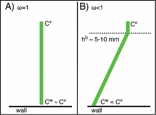
This is most easily illustrated for the case of irreversible condensation (i.e. a nonvolatile condensable vapor), where the near-surface concentration will tend toward zero if there are gas-phase diffusion limitations. When , mass transfer to the walls will be rate-limited by diffusion in a boundary layer near the walls and the gas-phase concentration next to the walls will be much lower than the bulk concentration; the flux will be driven by that concentration gradient, as illustrated in . In the reverse case, when
, there will be no concentration gradient; the gas-phase concentration next to the walls will be the same as the bulk, and the mass transfer will be rate-limited by mass accommodation.
Figure 4. The thickness of the wall boundary layer (hb) scales with the chamber turbulence parameter. For a typical value of ke = 0.1 s−1, the boundary thickness will be ∼1 cm. When 10 μg m−3 of 100-nm particles are deposited onto the wall, the particle spacing is ∼10 μm.
Some typical numbers are in order. Typical values for large chambers are s−1, and
cm2 s−1, giving a boundary layer diffusion velocity
cm s−1
m s−1. A typical molecular speed is
cm s−1, giving
. Thus, even extremely low wall mass accommodation coefficients are sufficient to drive the wall concentration effectively to zero and cause diffusion to limit wall uptake.
As with suspended particles, the collision frequency of vapors in the bulk of the chamber with the wall is found for :
[19]
Given the very small critical mass accommodation coefficient, it is highly likely that this collision frequency also gives the wall condensation sink, as essentially all vapors that get near the walls will ultimately accommodate with either the Teflon itself or particles deposited on the walls.
An 8 m3 chamber with 2 m × 2 m sides has S:V = 3 m−1 and thus a typical wall collision frequency (and presumably condensation sink) of s−1. This gives a wall-collision timescale for vapors of 8–10 min, which is the shortest possible lifetime of vapors against condensation to the chamber walls. Recent SVOC wall-loss measurements report a rate consistent with a vapor wall-loss timescale of 10–15 min (Krechmer et al. Citation2016; Ye et al. Citation2016), supporting our choice of
s−1as a typical value.
A central element of this development is the average wall mass accommodation coefficient. Here we assume that this is approximately the coverage weighted average of mass accommodation coefficient to Teflon, , and the mass accommodation coefficient to surface-deposited particles,
(designated with superscripts t and d, respectively), assuming a certain coverage of deposited particles θd. This is because the surface deposited particles will be much closer together than the effective diffusion length of the boundary layer. As shown in , a typical starting particle number concentration is Ns ∼ 1010 m−3, so after 10% of these particles have deposited, with Nd ∼ 109 m−3, the surface concentration in an 8 m3 chamber will be (V:S)Nd = 3.3 × 10⁸ m−2, giving an average area per particle of 3 × 10⁻⁹m2and thus an average separation of 55 µm. On the other hand, the characteristic boundary layer diffusion thickness is
= 1 cm. Thus, from the perspective of the chamber bulk, the walls will appear as the “gray” average of the wall surface and deposited particles (rather like a print newspaper image) with respect to any diffusing vapors. It is important to realize that the nominal laminar boundary layer thickness depends on the diffusion constant in a turbulent chamber; a species with high diffusivity (i.e. Helium) will diffuse through over a relatively large distance, while something with a low diffusivity (i.e. a 200 nm particle) will diffuse over a much smaller distance (Crump et al. Citation1983). Thus
[20]
Even though we typically operate experiments with a sufficient seed particle concentration to ensure that , the suspended surface-area concentration (the surface area to volume ratio of the suspended particles) is still extremely small, of order 5 × 10⁻⁴ m−1. Consequently, for any given run, we are assured that
, but also, almost by design, that there will be of order 10 times the necessary particle surface area for mass accommodation to deposited particles alone to exceed the critical mass accommodation coefficient threshold for diffusion to limit wall condensation even at the perfect Teflon limit.
However, there are two subtleties. First, the deposited particles are likely to deform from a spherical shape. Here we arbitrarily assume that the contact angle of the deposited particles is 90o and they will thus form a hemi-spherical lens. In this case the deposited hemi-spheres will expand to a diameter . The surface area of these hemispherical particles will be suppressed by a factor
compared to the corresponding suspended particles (not counting their flat bottoms). Other geometries are of course possible, but the microphysics becomes extremely complicated and the effects unverifiable; in general
will be an empirical factor, but we shall always use the spherical equivalent diameter dp as the independent variable. The surface coverage by deposited particles is thus:
[21]
Second, if the particles are in the transition regime (which is likely), there will also be a diffusion limitation for mass transfer from the average near-wall environment (with vapor concentration Cw) to the surface of the wall-deposited particles themselves. Just as with the suspended particles, this will be expressed as a Fuchs-like correction term, but for a slightly larger diameter (smaller Knudsen number) because of the deformation. Here we shall use the hemispherical assumption exclusively and fold any differences into the single-term . The transition-regime diffusion correction will slightly raise the effective mass accommodation coefficient for the deposited particles, if it is less than unity in the first place:
[22]
Given this, the wall condensation sink is[23]
Once the wall condensation sink is known, we can then calculate the net flux between the vapor phase and the wall region if we know the activity in the wall reservoir, [24]
Note that is not the gas-phase saturation ratio near the wall, but rather the activity within the reservoir(s). We developed the formulation described in this article while considering condensation to deposited particles and before fully considering condensation to the Teflon itself. While this treatment of the average mass accommodation coefficient and average reservoir activity is valid, it is awkward. In the future we will separate the diffusive flux of vapors between the bulk of the chamber and the wall region and also the various fluxes between the near-wall vapors and the wall reservoirs in order to determine the steady-state near-wall concentration,
, via a flux balance. Here we shall make simplifying assumptions to approximate
depending on context.
3.1.1. The perfect-Teflon limit
We are often interested in comparing the condensation to suspended and deposited particles. The condensation sink per deposited particle is[25] whereas the condensation sink per suspended particle is
[26]
The ratio of the condensation sink per deposited particle to the condensation sink per suspended particle is our definition of the flux multiplier, , from Equation (Equation14
[14] ). While the multiplier can be calculated for any situation where there is a flux from the vapor phase to the walls, we developed it based on the assumption that condensable organic vapors would not sorb to the Teflon walls themselves, and thus
. In most of the work below we shall calculate
directly based on Equation (Equation11
[11] ) (with or without including uptake to Teflon) but it is none-the-less useful to consider the effective factor for
, where αw = θd αd.
[27]
In this “perfect Teflon” limit, the value of evolves as particles deposit to the wall over the course of an experiment.
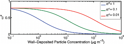
To illustrate the effect near-wall diffusion could have, we show in the dependence on deposited particle mass for 100 nm particles and three values of the particle mass accommodation coefficient. For this simulation we hold both populations at 100 nm (spherical diameter) and consider perfectly hemi-spherical deposited particles, so Fd = 0.79 is the asymptotic limit for ωd at small coverage. The curves in are almost entirely driven by the final term in square brackets in Equation (Equation27[27] ). As the wall deposited concentration rises, the average accommodation coefficient driven entirely by accommodation to the deposited particles quickly rises above the critical average value and wall diffusion limitations, and depending on the value of the mass accommodation coefficient to the particles themselves this transition occurs with between 1 and 100 µg m−3 deposited on the chamber walls. For example, an experiment targeting 10 µg m−3 final organic aerosol mass would encounter boundary-layer diffusion limitations (ω < Fd) after only 10% of the mass was deposited to the chamber walls if αi = 1 but have no boundary layer diffusion limitations at all for αi = 0.01. Experiments with higher final loading would almost certainly experience boundary layer diffusion limitations. This is alarming; there is strong evidence that
, and so if the perfect Teflon limit were to hold the conclusion is that typical chamber experiments with
would fall exactly in the transition regime where early in the experiment
would be near 1 but later it would fall off rapidly toward zero. One implication is that the
assumption is almost certainly not appropriate for aerosol aging experiments, even in the perfect-Teflon limit.
Figure 5. Dependence of the flux scaling factor ωd on the mass of wall-deposited particles. For larger particle mass accommodation coefficients, the ωd correction is less significant, indicating the mass transfer to the particles on the wall is uptake-limited.
A subtlety in this calculation is the treatment of the particle distribution deposited to the walls. In the ω = 1 case all the particles remain identical, and , but for ω < 1 the composition and size of wall-deposited particles evolves separately from the suspended particles. This also means that particles depositing at a given time are probably larger than particles that deposited earlier, and they probably also have a different composition. It might be necessary to treat this heterogeneous population explicitly. This is one of several examples where different reservoirs in the wall region (particles, adsorption to the Teflon, absorption to the Teflon, etc.) might have different activities for a given species and thus be out of equilibrium. This is a vexing issue that we shall explore throughout this article.
Because the wall-deposited particles are much closer to each other than the characteristic thickness of the diffusive boundary layer near the wall, we assume that the wall-deposited particle population equilibrates internally much more rapidly than with the suspended particles (in the perfect Teflon limit). Consequently, we assume a homogeneous wall-deposited population. We assume that the wall-bound particles have a single average particle diameter and composition (they are mono-modal and well mixed). The mass changes as the wall-deposited particles exchange mass with the vapor phase and also as more particles deposit to the wall. When mass exchange between the chamber bulk and the wall region is limited (ω < 1), the diameter of the depositing particles will not be the same as the average diameter of the particles already on the wall. By tracking only the mode diameter for each population, we thus assume that greater size resolution would not significantly affect our predictions of SOA yield. We explored the sensitivity of our model to this approximation by treating the wall-deposited particles as separate populations based on their deposition time. This did not significantly influence the model results, changing the predicted mass of the wall-deposited particles by less than 5%. Many other uncertainties in this problem are far larger.
4. Model results: Implications of deposited particles
4.1. Illustration of composition effects
To explore the implications of composition differences between the suspended population and the wall-deposited population at the perfect-Teflon limit, we simulate two extreme cases using two organic components (these simulations are comparable to the work presented in Trump et al. Citation[2014]). One of the constituents has a very low volatility (C* = 0.01 µg m−3) while the other is relatively volatile (C* = 1 µg m−3), though it is worth noting that almost all of the SVOCs in the typical “semi-volatile” equilibrium formulation of α-pinene SOA are more volatile than this (Presto and Donahue Citation2006). We initialize each simulation with 10 μg m−3 of one constituent on the chamber walls and simulate production of 20 μg m−3 of the other constituent as condensable vapors at a constant rate of 10 μg m−3 h−1 for 2 h. After 2 h, the vapor production rate instantaneously falls to zero. The simulations include a population of suspended, inorganic particles to provide an initial suspended condensation sink (1 min−1) in contrast to a wall condensation sink of 0.1 min−1. The particle wall-loss rate constant is 10−4 s−1 as in . This means that 90% of the vapors will initially condense on suspended particles. The organic mass accommodation coefficient is unity. In the first simulation, the low-volatility material is initially on the walls while the more volatile constituent is produced for 2 h. The reverse is true in the second simulation. This bounds possible interactions between suspended SOA production and wall-bound particles, where newly produced vapors can either be more or less volatile than the constituents on the walls.
In we present the mass evolution for each simulation in a composition stack plot. All organic reservoirs present in the simulations are shown: suspended particle mass in shades of green, wall-deposited particle mass in shades of blue, and vapor mass in shades of gray (barely visible because almost no mass resides in the vapor phase). The lighter shades correspond to more volatile organics. In addition to the forward simulation, we also perform an inverse calculation of the inferred SOA “yield”, based only on the vapors produced and any deposited particles. In the first case, the “actual” SOA production is 19 µg m−3 (out of 20, with 1 µg m−3 expected in the gas phase), while in the second case the “actual” SOA production is 19.99 µg m−3. In , we show the “actual” SOA production (blue) along with the inferred SOA production using the ω = 0 and ω = 1 empirical analysis methods.
Figure 6. Mass of organics in suspension, on particles deposited on the wall, and in the vapor phase (negligible) is shown for two illustrative cases. Condensable organic vapors are produced for 2 h in a chamber initially containing a population of organic particles deposited on the wall. In simulation (a), the added organics are volatile relative to the particles initially on the wall. In simulation (b), produced organics are less volatile. Lighter shades correspond to more volatile organics.
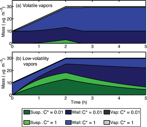
Figure 7. The apparent mass production vs. time for the simulations in calculated using the ω = 0 or ω = 1 assumption. In simulation (a), relatively non-volatile organics on the chamber walls suppress the observable SOA production. In simulation (b), the volatile organics on the wall contribute to particle growth and the yield is overestimated.
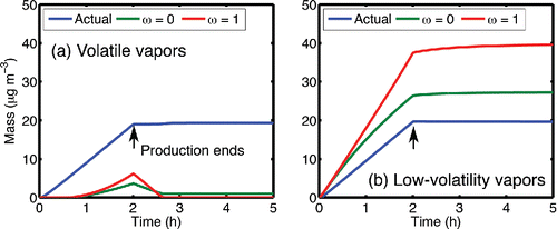
In the first simulation (), the produced organics are two orders of magnitude more volatile than the organics pre-deposited on the walls. In this case, the less-volatile material on the walls (the dark blue portion at t = 0) acts as a sink for the produced organics. The relatively volatile organics condense almost entirely to the wall-deposited particles; this is shown by the growth in the light-blue portion during the 2-h vapor-production period. Although 19 μg m−3 of SOA is produced, the SOA is not observed based on an analysis of suspended particle growth (); almost none of the SOA condenses onto suspended particles. Furthermore, since the SOA is relatively volatile (to the extent that C* = 1 µg m−3 is “volatile”) and the walls are lossy, the suspended particles evaporate quickly after production stops at t = 2 h. Note that by the end of the production period the activity of the “volatile” material in the deposited particles is roughly 0.66 (20 µg m−3out of 30 µg m−3 total) but there is still a strong gradient for condensation to the walls because the gas-phase activity is 1 over the pure suspended particles.
In the second simulation (), the wall-deposited particles contain the more-volatile organic compound. As the low-volatility vapors (the dark shades) condense on the seeds, the more-volatile organics from the wall population evaporate to equilibrate the particle compositions. The wall particles therefore act as a source of suspended organics, magnifying the observed SOA production (SOA is over predicted by 40-100%, see ). In this extreme case, ω is effectively negative—instead of taking up vapors, the wall-bound particles actually emit them.
These results demonstrate the importance of ensuring that the chamber walls are clean and free of organic compounds prior to any SOA experiment, and they will hold qualitatively whether volatile organics are contained in particles deposited to the walls or within the walls themselves, though the quantitative results will depend strongly on the activity of the semi-volatile organics in the wall region (deposited particles or the Teflon itself). Moreover, wall interactions should be carefully considered when experiments involve multiple generations of organic aging. For instance, the production of lower-volatility organics from second-generation chemistry could lead to situations that resemble case (b): mass transfer from the wall-deposited to the suspend particles could enhance apparent second-generation SOA yields, though at the perfect-Teflon limit. Case (a) suggests that at the extreme limit, an absorbing wall could completely suppress production of suspended organic-aerosol mass, leading to a gross under estimation of SOA production. This conclusion applies whether the wall is lossy because of deposited particles or because of sorption to the Teflon itself.
4.2. Typical SOA experiments at the perfect-Teflon limit
Next we shall explore the sensitivity of our model using a “traditional” semi-volatile SOA volatility distribution when the reaction rate is relatively slow, as wall-loss corrections are most important in this case. As before, we simulate 40 ppb (146 µg m−3) α-pinene reacting with 50 ppb O3(the lifetime of the vapor with respect to oxidation is τrxn= 2.4 h), which would produce ∼26 µg m−3of SOA in an ideal experiment. We use the stoichiometric yield parameterization for α-pinene ozonolysis to describe the vapor-phase production, using the same parameters as in Trump and Donahue Citation(2014) . We seed the simulated chamber with ammonium sulfate particles (dp = 200 nm) at a concentration of 1010 m−3, giving an initial collision frequency of vapors to particles of 0.05 s−1 (180 h−1). Particle deposition to the walls is described by a first-order, size-independent loss constant: kw= 1 × 10⁻⁴ s−1. We assume a constant value to isolate the effect of gas uptake on predicted aerosol yields.
Table 1. Actual and apparent SOA formed by reaction of α-pinene (40 ppbv) with ozone (50 ppbv, τrxn = 2.4 h) for different values of the particle accommodation coefficient.
We simulate low-ozone α-pinene SOA production experiments for different particle accommodation (αi) and chamber eddy diffusion coefficients (ke). We present simulation results for ke = 0.3 s−1 and αi = 1, 0.1, and 0.01 in , showing the evolution of suspended organic mass (shades of green) along with the mass of organic particles deposited to the wall (shades of blue). The collision frequency with the walls is 3.5 × 10⁻³ s−1, so only for αi = 0.01 does the suspended condensation sink fall below the wall condensation sink. However, even at this “perfect Teflon” limit, there is substantial vapor condensation to deposited particles; because SOA production is slow compared to particle wall losses, only 5–10 µg m−3 out of 26 µg m−3 total SOA ever appears in suspension; the proper wall-loss corrections thus vary between a factor of 2.5 and 5. Correction factors this large should always be a source of concern.
Figure 8. Mass of SOA produced on suspended particles and on wall-deposited particles for three different values of the particle mass accommodation coefficient (α). Lighter shades correspond to more volatile organics.
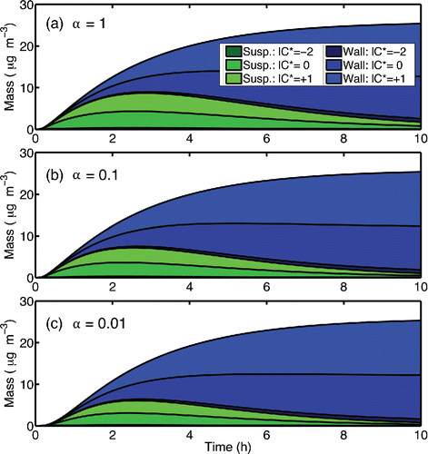
We can treat the simulated suspended aerosol concentration (Cs, the green portion of the stack plot in ) as synthetic data, along with the known ratio of suspended to deposited particles, and correct for wall diffusion using the empirical factor ω. As can be seen in , the suspended and deposited particle compositions remain similar in all of the simulations, and the corrections remain stable over the course of the simulation. We summarize the overall results in : we show the “actual” simulated SOA production (Pactual) along with the apparent SOA production obtained when we analyze the synthetic data using the common ω = 1 and ω = 0 wall-interaction assumptions (Pω = 1 and Pω = 0). We calculate Pω = 1 by assuming that all particles deposited on the wall have the same mass as those in suspension at all times (the deposited particles evolve identically to the suspended particles). We calculate Pω = 0 by assuming that the mass of a particle does not change after it is deposited. We have generally assumed that these two values (ω = 1 and ω = 0) bound the real production (Weitkamp et al. Citation2007), and in this case our assumption is valid.
The value of the particle mass accommodation coefficient strongly influences which of the two assumptions is most representative of the actual SOA yield. For example, for α = 1, the ω = 1 assumption would lead to a significant over-estimation of the SOA yield. However, for α = 0.01, the ω = 1 assumption is much more accurate. The result conforms to our earlier analysis; for α ≪ 1, near-wall diffusion is less important and the vapor concentrations at the wall remain very close to those in the bulk of the chamber. Our current best estimate is that the suspended-particle mass accommodation coefficients are larger than 0.1 (Saleh et al. Citation2013), and furthermore that the perfect Teflon limit is unrealistic (Matsunaga and Ziemann Citation2010; Zhang et al. Citation2015; Ye et al. Citation2016). Consequently, we expect that boundary layer diffusion will generally be rate limiting for mass transfer toward the chamber walls.
The eddy diffusivity coefficient, ke, is another uncertain parameter. When the particle mass accommodation coefficient is low, the yields are not sensitive to ke because diffusion to the wall is not rate limiting to condensation. We varied ke by one order of magnitude above and below the default value of 0.3 s−1 for the base case with α = 1 and summarize the sensitivity of the apparent net production to ke over this range of possible values in . Especially for low eddy diffusivity (slow chamber mixing and thus slow diffusion to the chamber walls) the error associated with the ω = 1 assumption grows very large, to greater than a factor of 3, while the ω = 0 assumption becomes more accurate because there is in fact little transfer to the walls.
Table 2. Influence of eddy diffusivity coefficient (ke) on apparent SOA formed.
Knowledge of the particle mass accommodation coefficient is required to constrain the chamber mass balance (). However, even if this parameter were known, the effect of wall loss on apparent SOA yield would be difficult to predict heuristically. As particles accumulate on the chamber wall, near-wall diffusive limitations also increase, and these factors have competing influences on the condensation sink of the wall-deposited particles. Further, studies of the accommodation coefficient of SOA suggest that α ⪆ 0.1 (Saleh et al. Citation2013). In this middle range, neither of the limiting assumptions accurately approximates the total SOA production. A smog–chamber model that includes the explicit calculation of ωd would probably be needed to constrain the influence of wall loss on SOA yields, especially when formation chemistry is slow, even at the perfect-Teflon limit; however, we know that the perfect-Teflon limit is a fantasy.
5. Treatment of Teflon absorption
5.1. Model description
Matsunaga and Ziemann Citation(2010) demonstrated that organic vapors can sorb to the walls of FEP Teflon chambers, and subsequent studies have confirmed this (Matsunaga and Ziemann Citation2010; Zhang et al. Citation2015; Ye et al. Citation2016). Matsunaga and Ziemann Citation(2010) proposed that organics can absorb reversibly into a thin disrupted layer of Teflon near the film surface. The potential mass concentration of such a layer is enormous; a layer 1 µm thick has a mass concentration of CTef = 1 g m−2, assuming a density of 1000 kg m−3. For an 8 m3 chamber with S:V = 3 m−1, the equivalent mass concentration would be 3 g m−3. Those authors suggest that organics may have a finite but small solubility in Teflon, and modeled the sorptive behavior of semi-volatile organics with an effective wall mass concentration of order 3 mg m−3. This implies an activity coefficient of order g/g that can vary by up to an order of magnitude depending on the chemical structure of the molecule. Here we assume that the Teflon sorption properties can be described by an equivalent aerosol mass concentration
[28] so that the activity of a species absorbed in the Teflon will be
[29] where Coi is the saturation mass concentration of species i. This is directly analogous to the activity of organics in wall-deposited particles with one very important difference. Because the activity coefficients are very large, it is reasonable to assume that the individual organics do not interact with each other while sorbed in the Teflon (this is the Henry's law limit).
The other critical unknown is the accommodation coefficient of the Teflon, for use in Equation (Equation17
[17] ). If it is within a few orders of magnitude of unity, then accommodation to the Teflon and the activity in the Teflon will dominate vapor-wall exchange, but if it is much lower, then the activity in deposited particles will dominate the exchange. In we show time scales for absorption to a 10 m3 chamber as a function of
for a clean wall without deposited particles, where
and ke = 0.3 s−1. These are the inverse of the wall condensation sink, given by Equation (Equation15
[15] ).
Figure 9. Dependence of absorptive timescale (τTef) on the Teflon accommodation coefficient (αt) for a 10 m3 Teflon chamber with an eddy diffusion coefficient of 0.3 s−1.
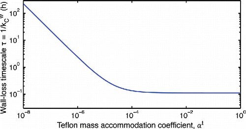
Matsunaga and Ziemann Citation(2010) report wall equilibration timescales between 8 and 60 min for organic vapors in a 1.7 m3 Teflon chamber. Because these experiments were conducted in the absence of other organics, can be related to the reported timescales using Equation (Equation16
[16] ); this gives an experimental range of 10−6 <
< 10−5; however, we cannot exclude the possibility that the accommodation coefficients of organics with the Teflon walls might also be much larger, with the equilibrium timescale being limited entirely by diffusion to the walls. The range we select as a base case is perhaps the most interesting, because the effective wall accommodation coefficient will be evenly split between uptake to Teflon and deposited particles (assuming that the accommodation coefficient of organics to organic particles is near unity).
5.2. Model results: Implications of Teflon absorption
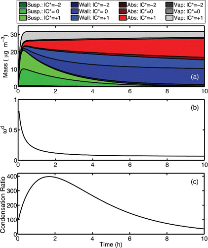
To explore possible implications to SOA formation experiments, we extend our dynamic smog–chamber model to include Teflon absorption. In , we show a “base-case” simulation that represents the reaction of 40 ppbv α-pinene with 1500 ppbv ozone (first-order loss frequency 1/τrxn = 12 h−1) in the presence of an absorbing wall with a wall condensation sink = 1.8 h−1 (ke = 0.3 s−1,
= 5×10⁻⁶). To represent typical experimental conditions, we “seed” the chamber with inorganic particles (dp = 200 nm, Ns = 1 × 10¹⁰ m−3), which gives an initial suspended-particle condensation sink
∼ 180 h−1.
Figure 10. (a) Formation of SOA mass and condensable vapors in a base-case simulation including Teflon absorption (seed condensation sink = 180 h−1 and = 5×10⁻⁶). The organic mass is shown as a composition stack plot, with the suspended particle mass shown in shades of green, wall-deposited particle mass in blue, the Teflon absorbed mass in red, and the condensable vapors in gray. Lighter shades represent more volatile organics. (b) Resistance to Teflon absorption (ωd) and (c) the ratio of the suspended condensation sink to the wall condensation sink over the course of the simulation.
Based on the work of Matsunaga and Ziemann Citation(2010), we use a value of = 2 × 10³μg m−3 for the equivalent aerosol mass concentration of the Teflon walls, independent of the absorbing species. Their work indicates that this value could in fact be an order of magnitude greater; however, as we will show, Teflon absorption is likely to be kinetically limited in many SOA-formation experiments. Formation experiments that involve slow chemistry are an important exception. In this model, we calculate the relative contributions of deposited particles and the Teflon walls to the wall condensation sink using the average accommodation coefficient in Equation (Equation20
[20] ) and then apportion the fluxes of vapors to each reservoir based on that fraction. This is an approximation that neglects mass transfer between the deposited particles and the Teflon that was forced by the historical development of the model using Equation (Equation20
[20] ) rather than explicitly treating the flux balances and near wall concentrations Cw for each species.
In we show the mass evolution in this base case for the organic vapors as well as all condensed-phase reservoirs (suspended particles, wall-deposited particles, mass absorbed directly to the Teflon walls) as a colored stack plot. All simulations use = 1. We show the modeled values of ωd for this case in . The initial value is determined by
and the shape factor Fd; however, as particles deposit to the walls and the average wall accommodation coefficient (
) increases, the value of ωd decreases. In we also show the ratio of the suspended-particle condensation sink to the wall condensation sink (
/
) for the base case. The initial value of this ratio is 100 and remains high during the early parts of the simulation when the SOA precursor is reacting. This means that the vast majority (>99%) of the condensable vapors interact with and accommodate to the suspended particles before they interact with anything near the walls; however, a substantial amount of the SVOC with C* = 10 µg m−3 is in the gas phase, as indicated by the light gray band in . These vapors are continuously lost to the Teflon, causing a corresponding buildup of light red mass. The gas-phase activity of the SVOC quickly reaches approximately 0.5 (5/10 µg m−3), and this level is sustained by the suspended particles while material sorbs into the Teflon from the gas phase. Ye et al. Citation(2016) exploited this behavior to measure the wall-loss rate constants for SVOCs in the CMU chamber. Conversely, the large majority of the less volatile constituents move from the bulk of the chamber to the wall region via particle deposition, as their mass fraction in the suspended particles (vs. the vapors) is always very high.
We explore the sensitivity of the absorption model to the seed concentration, Teflon accommodation coefficient, and terpene oxidation rate (O3 concentration) and show selected results in . It is important to note that in these simulations, we do not represent particle nucleation; this will likely occur when the seed concentration is low, thereby increasing observed SOA. The simulation results therefore represent the maximum influence of the described absorption processes on SOA yields. We also do not simulate particle coagulation, which would become significant in the very high initial seed condensation sink cases, were we simply increase the number of 200 nm diameter seed particles.
Figure 11. Formation of SOA mass and condensable vapors in Teflon-absorption sensitivity studies S1-S4. For each, the organic mass is shown as a composition stack plot, with the suspended particle mass shown in shades of green, wall-deposited particle mass in blue, the absorbed mass in red, and the condensable vapors in gray. Lighter shades represent more volatile organics.
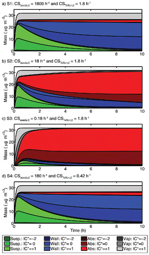
Using the synthetic data, we calculate apparent net production (P) values from the suspended mass concentrations, the particle loss rate, and the commonly used “ω = 1” or “ω = 0” empirical corrections to account for mass transfer to wall-deposited particles and present the results in . We calculate the reported yields at t = 3 h, rather than at the end of the 10-h simulation, because the interpretation is complicated by the fact that particle evaporation occurs in many cases. When particle evaporation occurs, the calculated production will decrease over time. For this reason, we also report the “maximum” net production predicted using both methods and generally use this for comparisons.
Table 3. Simulation parameters and apparent SOA formed (μg m−3) for a sequence of conditions involving sorption to Teflon chamber walls.
For the reaction of 40 ppbv α-pinene with excess ozone, the total simulated net production of SOA (in absence of all wall effects, including absorption which can influence OA partitioning) is Pactual ∼ 26 μg m−3. As shown in , the base-case description results in an apparent maximum net production of 23–24 μg m−3 or ∼90% of the actual net production. This is because the condensation sink of the seed particles is high relative to the wall condensation sink during the rapid SOA-formation period () and accounting for deposition of particles (the blue in as it appears online) accounts for almost all of the wall losses.
In simulation S1, the increased seed concentration does not improve the yield predictions (), and the reduced seed concentration ( = 18 h−1) in study S2 does not drastically reduce the maximum observed SOA production, which is 85% of Pactual (). Only when we reduce
to 0.18 h−1, we only observe 25% of Pactual on the suspended particles. When the timescale for Teflon absorption (1/
) exceeds the timescale for seed condensation (1/
), the majority of the produced SOA will be lost to the chamber walls (). A crucial design parameter for smog-chamber experiments is thus for the condensation sink to suspended particles to exceed the (maximum possible) condensation sink to the chamber walls (McVay et al. Citation2016). In this case, one is guaranteed that condensable vapors will encounter suspended seed particles before they encounter the chamber wall.
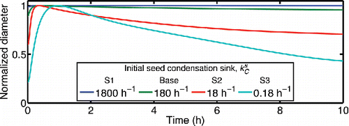
Figure 12. Normalized particle diameter (dP/dP,max) for different values of the initial seed condensation sink ( = 180 h−1 for the base case). The other
values correspond to simulations S1-S3 as labeled.
In sensitivity studies S4-S5, we vary the assumed value of (
) through an order of magnitude. Sensitivity study S4 reveals that for
= 0.42 h−1 (
= 1 × 10⁻⁶), wall absorption would not significantly influence the observed net production (“max” P ranges from 25–26 μg m−3 or essentially 100% of Pactual). Sensitivity study S5 (
= 2.9 h−1 or
= 1 × 10⁻⁵) reveals that the calculated maximum SOA production is slightly less than the net production calculated from the base-case (21–22 vs. 22–24 μg m−3), indicating that the base-case results are only moderately sensitive to a factor of five increase to the assumed value of
, as diffusion limitations limit fluxes to the walls in all of the simulations. This is also consistent with our finding that the critical parameter is the ratio of the suspended to wall condensation sinks, and that this ratio should be substantially larger than unity for results to be robust.
The base-case simulation includes a fast reaction, with a precursor loss timescale much faster than the wall-loss timescale. In sensitivity studies S6-S8, we vary the α-pinene reaction rate (O3 concentration) to determine whether absorption has a greater influence on predicted SOA yields when gas-phase chemistry is slowed down. For simulations S6 and S7 (1/τrxn= 6.3 h−1and 2.1 h−1), the maximum Pω = 1 values do not differ greatly from the base-case (23 vs. 24 μg m−3). However, in simulation S8, when the gas-phase chemistry is especially slow (1/τrxn = 0.41 h−1), the Pω = 0 value is significantly reduced (only 15 μg m−3 or ∼60% of Pactual is observed). The Pω = 1 is actually much higher in this case, because the uncertainty range of the observed yield is always wider for slow chemistry. These results indicate that as long as the reaction timescale (τrxn) is less than the timescale for Teflon absorption (1/), a relatively slower reaction will not cause absorption to have a greater impact on observed SOA yields. However, when τrxn is longer than the absorption timescale, absorption can strongly reduce the apparent yield.
shows the time-dependence of the suspended-particle diameter in the base-case simulation; we also show the results from the first three sensitivity studies. In simulations S1-S3, we vary the seed concentration (). For the base-case simulation and sensitivity study S1, the rate of diameter change due to evaporation for the suspended particles is <1 nm h−1. A change this gradual is not likely to be observed in smog-chamber experiments. We assumed lower seed concentrations for simulations S2 and S3 and the predicted evaporation rate is high (); this particle evaporation would be apparent in a typical chamber experiment. For cases S4-S7, the simulations also predict very slow evaporation of the suspended particles (<1 nm h−1) that is not likely to be observable. The minimal diameter change for the high seed condensation sink cases arises at least in part because the SOA production is spread over so many seeds; there is also little diameter growth during SOA formation. However, α-pinene SOA formation experiments in the CMU chamber, with significant diameter growth on seeds during SOA formation, have revealed that the modal particle diameter is generally quite stable after the precursor is completely consumed (Presto), suggesting that substantial losses via absorption to Teflon likely did not influence those experiments. Alternative explanation is that the SOA is not very volatile (Ehn et al. Citation2014) or that the particles become so viscous that evaporation is limited (Perraud et al. Citation2012).
6. Adsorption
Recent conversation about chamber-wall interactions has focused on absorption of vapors into a thin disturbed surface layer of the film, but adsorption of vapors to the film surface remains a possibility. Just as a 1µm layer of Teflon represents 1 g m−2, a 1 nm adsorbed monolayer represents mg m−2, with surface coverage
. Given S:V = 8 m−1, this corresponds to a gas-phase equivalent concentration
= 8000 µg m−3. Thus, if a typical SOA experiment with 8 µg m−3 of SOA were influenced by adsorption with surface coverage of
, the adsorbed mass would be the same as the suspended mass (a 100% interference). This simple calculation caused one of us to sit bolt upright in bed more than a decade ago.
Adsorption would presumably follow a Langmuir type isotherm, with an equilibrium coverage given a characteristic gas-phase mass concentration for half coverage, [30] so the adsorbed equivalent mass concentration will be
[31]
If the surface coverage remains low for all adsorbed species, the adsorptive isotherm and the absorptive model of Matsunaga and Ziemann Citation(2010) are sufficiently similar that they would be difficult to differentiate experimentally. Those authors argue that the quantity of sorbed species argues for the absorptive model. A potential difference could be the potential for competitive adsorption, where more volatile but much more abundant organics might fill most active sites on the film surface and prevent adsorption of rarer low volatility species.
To test for potential losses to Teflon, we constructed a tandem DMA experiment using a 7.62 m long 0.48 cm ID diameter FEP Teflon tube as a “denuder” and passed size-selected particles of dodecanol and SOA generated from α-pinene ozonolysis through the tube. We describe the experiments in the online supplemental information (SI), but in both cases the particles passing through the Teflon tube remained within 0.5% of their original size, leading us to conclude that significant adsorption to (FEP) Teflon was unlikely.
7. Wall nucleation
At least one more type of wall interaction could influence chamber experiments; we have treated particle deposition to walls, and sorption into the walls, but surfaces can also serve as sites for heterogeneous nucleation. Nucleation thresholds could explain observed behavior in SOA experiments, such as the low mass yields observed for α-pinene and β-pinene reactions under some conditions (Pathak et al. Citation2007, Citation2008). These experiments showed that for the reaction of an equivalent amount of terpene, the observed SOA yield is greatly influenced by both the rate of reaction and the presence of seed particles. When seed particles are present, some produced SOA is observed even for very slow chemistry. However, when there are no seeds and chemistry is slow, there is no observable SOA production. We describe a treatment of wall nucleation in the SI and summarize the results of all simulations in . The aerosol mass fraction (AMF) is the ratio of the observable aerosol production (calculated as Pω = 0) to the amount of SOA precursor reacted. These results are qualitatively consistent with Figure 4 of Pathak et al. Citation(2008).
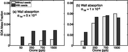
However, if sorption to Teflon is substantial, it is unlikely that near-wall saturation ratios could grow high enough to drive nucleation. Consequently, we also consider that the dependency of the observed SOA formation on reaction conditions (rate and seed presence) might be explained by Teflon absorption. To test this hypothesis, we rerun all of the simulations represented in with the wall absorption process represented rather than wall nucleation. summarizes the absorption results based on = 5 × 10⁻⁶ (the base-case assumption for Teflon absorption). The SOA formation trend differs from the work of Pathak et al., who reported approximately equivalent mass yields for the seeded- and unseeded- reactions at 1500 ppbv ozone; this is not the case for the results shown in . We also simulated the set of experiments using
= 1 × 10⁻⁶ (). These results are qualitatively consistent with the work of Pathak et al., however, these are based on the lowest coefficient considered in the absorption sensitivity study. For
= 1 × 10⁻⁶, absorption did not influence SOA production in the seeded experiments having faster chemistry (.
Figure 13. Comparison of apparent SOA formed when wall- and homogenous-nucleation are represented in the model. Apparent SOA mass is shown for the reaction of 8 ppbv α-pinene with and without seeds for 50, 250, 750, and 1500 ppbv ozone.
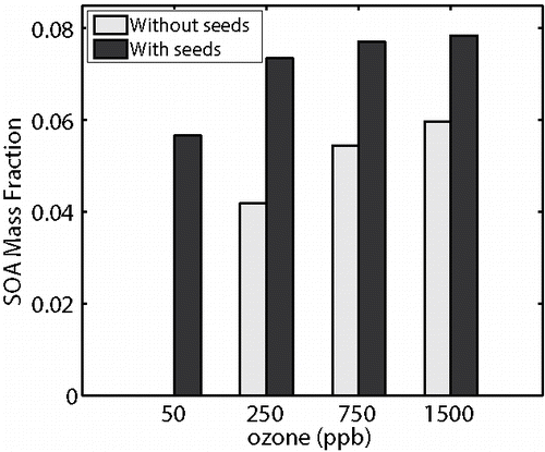
Figure 14. Comparison of apparent SOA formed when we treat both wall absorption and homogenous nucleation. We show apparent SOA mass for the reaction of 8 ppbv a-pinene with and without seeds for 50, 250, 750, and 1500 ppbv ozone. For panel (a) we show results for aTefD 5£10i6 and for panel (b) we show results for aTefD 1£10i6.
8. Conclusions
SOA formation experiments are mass balances, and here we have considered several reservoirs and processes that can influence those mass balances without being directly observable. These involve either condensation of vapors to Teflon chamber walls themselves (via absorption into a semi-permeable surface layer in the polymer) or condensation of vapors to particles on the walls. The particles on the walls in turn can arise either via deposition of suspended particles or via heterogeneous nucleation.
The most vexing aspect of condensation to chamber walls is that it occurs between two traditionally unmeasured reservoirs: condensable vapors are produced via gas-phase chemistry (oxidation of volatile precursors) but until recently they have not been observed in the gas phase. The various wall phases also evade direct measurement. It is the production of those condensable vapors (and their volatility distribution) that we seek to constrain, and the transfer between unobserved reservoirs impedes this.
We developed the model presented here over the past decade, with significant contributions by the first and second authors during their doctoral dissertation research. Several of the limiting cases we presented represent the state of the art understanding of chamber experiments at various times during that period. Most notably, our focus on wall effects moved from adsorption, to deposition and mass transfer limitations between suspended and deposited particles, as well as wall nucleation, and finally to absorption into Teflon. This model contains some ad hoc features because we do not treat transfer among those various potential wall reservoirs explicitly. We combine transfer to the wall reservoirs with diffusion limitations to the wall region in a single expression involving the average wall accommodation coefficient. In a future implementation, we shall explicitly treat the full flux balance near the walls to track the steady-state near-wall concentration.
One interesting aspect of the three major wall reservoirs we have considered here is their different behavior with regard to mixtures. Wall-deposited particles constitute an organic mixture with synergistic interactions of (mutually soluble) species that closely resembles the interactions of the suspended particles. A full equilibrium is thus theoretically possible in which transfer from the suspended to the deposited state changes the suspended particle number but not the particle (or vapor) composition. Absorption is antagonistic, with competitive adsorption potentially resulting in saturation of various species depending on the vapor concentrations of others; this could reach an equilibrium at relatively low surface coverages and only minimally perturb SOA production experiments. Wall absorption may proceed without interactions among different vapors because the presumably very high activity coefficients imply that the actual mass fractions of organics within the Teflon matrix are very small. The none-the-less high capacity of the Teflon walls however means that the walls could substantially perturb SOA production experiments. A critical unknown is the mass accommodation coefficient of vapors to the Teflon; wall diffusion limitations make simple models insensitive to this value above the critical value where wall diffusion limits mass transfer. However, as we have shown, it is possible that the overall average mass accommodation coefficient of the walls could be controlled by deposited particles or the Teflon itself. This in turn will influence whether particle or Teflon absorption controls interactions between vapors and the walls, with important implications for SOA experiments.
The model simulations we show here do, however, provide guidance for experimental design, both to minimize the errors associated with wall condensation and also to constrain the uncertain parameters associated with it. First, results are most robust when the both the gas-phase chemical timescale and the condensation timescale to suspended particles is rapid compared to wall condensation and deposition timescales. At this “fast chemistry—fast condensation (high seed)” limit, derived SOA production values appear to be robust. However, fast chemistry may require oxidant levels and particle growth rates that are much higher than ambient values, and so there is a danger that the oxidation mechanism and the condensation dynamics may be perturbed (for example by changing peroxy radical branching or encountering diffusion limitations within particles, which we do not consider here). Second, mass-transfer limitations caused by diffusion through the gas-phase boundary layer near the chamber walls can provide a valuable buffer for experiments, but the specific nature of the wall interaction will also determine when and if this diffusion causes a depletion of vapor concentrations near the walls and thus limits wall condensation. Finally, all of these issues would be greatly simplified if the vapors were measured comprehensively and quantitatively in the gas phase.
UAST_1232858_Supplemental_file.zip
Download Zip (709.5 KB)Funding
This work was supported by grant CHE1412309 from the National Science Foundation.
References
- Burkholder, J. B., Baynard, T., Ravishankara, A. R., and Lovejoy, E. R. (2007). Particle Nucleation Following the O-3 and OH Initiated Oxidation of Alpha-Pinene and Beta-Pinene Between 278 and 320 K. J. Geophys. Res.-Atmos., 112, D10216, doi:10.1029/2006JD007783.
- Cocker, D. R., Flagan, R. C., Seinfeld, J. H. (2001). State-of-the-Art Chamber Facility for Studying Atmospheric Aerosol Chemistry. Environ. Sci. Technol., 35:2594–2601.
- Crump, J. G., Flagan, R. C., and Seinfeld, J. H. (1983). Particle Wall Loss Rates in Vessels. Aerosol Sci. Technol., 2:303–309.
- Donahue, N. M., Robinson, A. L., Stanier, C. O., and Pandis, S. N. (2006). Coupled Partitioning, Dilution, and Chemical Aging of Semivolatile Organics. Environ. Sci. Technol., 40:02635–02643.
- Ehn, M., Thornton, J. A., Kleist, E., Sipila, M., Junninen, H., Pullinen, I., Springer, M., Rubach, F., Tillmann, R., Lee, B., Lopez-Hilfiker, F., Andres, S., Acir, I.-H., Rissanen, M., Jokinen, T., Schobesberger, S., Kangasluoma, J., Kontkanen, J., Nieminen, T., Kurten, T., Nielsen, L. B., Jorgensen, S., Kjaergaard, H. G., Canagaratna, M., Dal Maso, M., Berndt, T., Petaja, T., Wahner, A., Kerminen, V.-M., Kulmala, M., Worsnop, D. R., Wildt, J., and Mentel, T. F. (2014). A Large Source of Low-Volatility Secondary Organic Aerosol. Nature, 506:476–479.
- Huff Hartz, K., Rosenorn, T., Ferchak, S., Raymond, T. M. Bilde, M., Donahue, N. M., and Pandis, S. N. (2005). Cloud Condensation Nuclei Activation of Monoterpene and Sesquiterpene Secondary Organic Aerosol. J. Geophys. Res.-Atmos., 110, D14208, doi:10.1029/2004JD005754.
- Hennigan, C. J., Miracolo, M. A., Engelhart, G. J., May, A. A., Presto, A. A., Lee, T., Sullivan, A. P., McMeeking, G. R., Coe, H., Wold, C. E., Hao, W. M., Gilman, J. B., Kuster, W. C., de Gouw, J., Schichtel, B. A., Collett, J. L., Kreidenweis, S. M., and Robinson, A. L. (2011). Chemical and Physical Transformations of Organic Aerosol from the Photo-Oxidation of Open Biomass Burning Emissions in an Environmental Chamber. Atmos. Chem. Phys., 11:7669–7686.
- Hildebrandt, L., Donahue, N. M., and Pandis, S. N. (2009). High Formation of Secondary Organic Aerosol from the Photo-Oxidation of Toluene. Atmos. Chem. Phys., 9:2973–2986.
- Kalberer, M., Paulsen, D., Sax, M., Steinbacher, M., Dommen, J., Prevot, A. S. H., Fisseha, R., Weingartner, E., Frankevich, V., Zenobi, R., and Baltensperger, U. (2004). Identification of Polymers as Major Components of Atmospheric Organic Aerosols. Science, 303:1659–1662.
- Karl, M., Brauers, T., Dorn, H. P., Holland, F., Komenda, M., Poppe, D., Rohrer, F., Rupp, L., Schaub, A., and Wahner, A. (2004). Kinetic Study of the OH-Isoprene and O3-Isoprene Reaction in the Atmosphere Simulation Chamber, SAPHIR. Geophys. Res. Lett., 31, L05117, doi:10.1029/2003GL019189.
- Kirkby, J., Curtius, J., Almeida, J., Dunne, E., Duplissy, J., Ehrhart, S., Franchin, A., Gagne, S., Ickes, L., Kurten, A., Kupc, A., Metzger, A., Riccobono, F., Rondo, L., Schobesberger, S., Tsagkogeorgas, G., Wimmer, D., Amorim, A., Bianchi, F., Breitenlechner, M., David, A., Dommen, J., Downard, A., Ehn, M., Flagan, R. C., Haider, S., Hansel, A., Hauser, D., Jud, W., Junninen, H., Kreissl, F., Kvashin, A., Laaksonen, A., Lehtipalo, K., Lima, J., Lovejoy, E. R., Makhmutov, V., Mathot, S., Mikkila, J., Minginette, P., Mogo, S., Nieminen, T., Onnela, A., Pereira, P., Petaja, T., Schnitzhofer, R., Seinfeld, J. H., Sipila, M., Stozhkov, Y., Stratmann, F., Tome, A., Vanhanen, J., Viisanen, Y., Vrtala, A., Wagner, P. E., Walther, H., Weingartner, E., Wex, H., Winkler, P. M., Carslaw, K. S., Worsnop, D. R., Baltensperger, U., and Kulmala, M. (2011). Role of Sulphuric Acid, Ammonia and Galactic Cosmic Rays in Atmospheric Aerosol Nucleation. Nature, 476:429–U477.
- Koch, S., Winterhalter, R., Uherek, E., Kolloff, A., Neeb, P., and Moortgat, G. K. (2000). Formation of New Particles in the Gas-Phase Ozonolysis of Monoterpenes. Atmos. Environ., 34:4031–4042.
- Krechmer, J. E., Pagonis, D., Ziemann, P. J., and Jimenez, J. L. (2016). Quantification of Gas-Wall Partitioning in Teflon Environmental Chambers Using Rapid Bursts of Low-Volatility Oxidized Species Generated in Situ. Environ. Sci. Technol., 50:5757–5765.
- Kroll, J. H., and Seinfeld, J. H. (2005). Representation of Secondary Organic Aerosol Laboratory Chamber Data for the Interpretation of Mechanisms of Particle Growth. Environ. Sci. Technol., 39:4159–4165.
- Kroll, J. H., and Seinfeld, J. H. (2008). Chemistry of Secondary Organic Aerosol: Formation and Evolution of Low-Volatility Organics in the Atmosphere. Atmos. Environ., 42:3593–3624.
- Li, D., Xie, M., and Neumann, A. W. (1993). Vapor Adsorption and Contact Angles on Hydrophobic Solid-Surfaces. Colloid Polymer Sci., 271:573–580.
- Matsunaga, A., and Ziemann, P. J. (2010). Gas-Wall Partitioning of Organic Compounds in a Teflon Film Chamber and Potential Effects on Reaction Product and Aerosol Yield Measurements. Aerosol Sci. Technol., 44:881–892.
- McMurry, P. H., and Grosjean, D. (1985). Gas and Aerosol Wall Losses in Teflon Film Smog Chambers. Environ. Sci. Technol., 19:1176–1182.
- McVay, R. C., Cappa, C. D., and Seinfeld, J. H. (2014). Vapor-Wall Deposition in Chambers: Theoretical Considerations. Environ. Sci. Technol., 48:10251–10258.
- McVay, R. C., Zhang, X., Aumont, B., Valorso, R., Camredon, M., La, Y. S., Wennberg, P. O., and Seinfeld, J. H. (2016). SOA Formation from the Photooxidation of Alpha-Pinene: Systematic Exploration of the Simulation of Chamber Data. Atmos. Chem. Phys., 16:2785–2802.
- Odum, J. R., Hoffmann, T., Bowman, F., Collins, D., Flagan, R. C., Seinfeld, J. H. (1996). Gas/Particle Partitioning and Secondary Organic Aerosol Yields. Environ. Sci. Technol., 30:2580–2585.
- Pathak, R., Donahue, N. M., and Pandis, S. N. (2008). Ozonolysis of Beta-Pinene: Temperature Dependence of Secondary Organic Aerosol Mass Fraction. Environ. Sci. Technol., 42:5081–5086.
- Pathak, R. K., Stanier, C. O., Donahue, N. M., and Pandis, S. N. (2007). Ozonolysis of Alpha-Pinene at Atmospherically Relevant Concentrations: Temperature Dependence of Aerosol Mass Fractions (yields). J. Geophys. Res.-Atmos., 112, D03201, doi:10.1029/2006JD007436.
- Paulson, S. E., Pandis, S. N., Baltensperger, U., Seinfeld, J. H., Flagan, R. C., Palen, E. J., Allen, D. T., Schaffner, C., Giger, W., and Portmann, A. (1990). Characterization of Photochemical Aerosols from Biogenic Hydrocarbons. J. Aerosol. Sci., 21:S245–S248.
- Perraud, V., Bruns, E. A., Ezell, M. J., Johnson, S. N., Yu, Y., Alexander, M. L., Zelenyuk, A., Imre, D., Chang, W. L., Dabdub, D., Pankow, J. F., and Finlayson-Pitts, B. J. (2012). Nonequilibrium Atmospheric Secondary Organic Aerosol Formation and Growth. Proc. Natl. Acad. Sci. USA, 109:2836–2841.
- Pierce, J. R., Engelhart, G. J., Hildebrandt, L., Weitkamp, E. A., Pathak, R. K., Donahue, N. M., Robinson, A. L., Adams, P. J., and Pandis, S. N. (2008). Constraining Particle Evolution from Wall Losses, Coagulation, and Condensation-Evaporation in Smog-Chamber Experiments: Optimal Estimation Based on Size Distribution Measurements. Aerosol Sci. Technol., 42:1001–1015.
- Presto, A. A., and Donahue, N. M. (2006). Investigation of Alpha-Pinene Plus Ozone Secondary Organic Aerosol Formation at Low Total Aerosol Mass. Environ. Sci. Technol., 40:3536–3543.
- Saathoff, H., Naumann, K. H., Mohler, O., Jonsson, A. M., Hallquist, M., Kiendler-Scharr, A., Mentel, T. F., Tillmann, R., and Schurath, U. (2009). Temperature Dependence of Yields of Secondary Organic Aerosols from the Ozonolysis of Alpha-Pinene and Limonene. Atmos. Chem. Phys., 9:1551–1577.
- Saleh, R., Donahue, N. M., and Robinson, A. L. (2013). Time Scales for Gas-Particle Partitioning Equilibration of Secondary Organic Aerosol Formed from Alpha-Pinene Ozonolysis. Environ. Sci. Technol., 47:5588–5594.
- Stanier, C. O., Pathak, R. K., Pandis, S. N. (2007). Measurements of the Volatility of Aerosols From Alpha-Piniene Ozonolysis. Environ. Sci. Technol., 41:2756–2763.
- Tolocka, M. P., Jang, M., Ginter, J. M., Cox, F. J., Kamens, R. M., and Johnston, M. V. (2004). Formation of Oligomers in Secondary Organic Aerosol. Environ. Sci. Technol., 38:1428–1434.
- Trostl, J., Chuang, W. K., Gordon, H., Heinritzi, M., Yan, C., Molteni, U., Ahlm, L., Frege, C., Bianchi, F., Wagner, R., Simon, M., Lehtipalo, K., Williamson, C., Craven, J. S., Duplissy, J., Adamov, A., Almeida, J., Bernhammer, A. K., Breitenlechner, M., Brilke, S., Dias, A., Ehrhart, S., Flagan, R. C., Franchin, A., Fuchs, C., Guida, R., Gysel, M., Hansel, A., Hoyle, C. R., Jokinen, T., Junninen, H., Kangasluoma, J., Keskinen, H., Kim, J., Krapf, M., Kurten, A., Laaksonen, A., Lawler, M., Leiminger, M., Mathot, S., Mohler, O., Nieminen, T., Onnela, A., Petaja, T., Piel, F. M., Miettinen, P., Rissanen, M. P., Rondo, L., Sarnela, N., Schobesberger, S., Sengupta, K., Sipilaa, M., Smith, J. N., Steiner, G., Tome, A., Virtanen, A., Wagner, A. C., Weingartner, E., Wimmer, D., Winkler, P. M., Ye, P. L., Carslaw, K. S., Curtius, J., Dommen, J., Kirkby, J., Kulmala, M., Riipinen, I., Worsnop, D. R., Donahue, N. M., and Baltensperger, U. (2016). The Role of Low-Volatility Organic Compounds in Initial Particle Growth in the Atmosphere. Nature, 533:527–531.
- Trump, E. R., and Donahue, N. M. (2014). Oligomer Formation Within Secondary Organic Aerosols: Equilibrium and Dynamic Considerations. Atmos. Chem. Phys., 14:3691–3701.
- Trump, E. R., Riipinen, I., and Donahue, N. M. (2014). Interactions Between Atmospheric Ultrafine Particles and Secondary Organic Aerosol Mass: A Model Study. Boreal Environ. Res., 19:352–362.
- Weitkamp, E. A., Sage, A. M., Pierce, J. R., Donahue, N. M., and Robinson, A. L. (2007). Organic Aerosol Formation from Photochemical Oxidation of Diesel Exhaust in a Smog Chamber. Environ. Sci. Technol., 41:6969–6975.
- Ye, P., Ding, X., Hakala, J., Hofbauer, V., Robinson, E. S., and Donahue, N. M. (2016). Vapor Wall Loss of Semi-Volatile Organic Compounds in a Teflon Chamber. Aerosol Sci. Technol., 50:822–834.
- Yeh, G. K., and Ziemann, P. J. (2014). Alkyl Nitrate Formation from the Reactions of C-8-C-14 n-Alkanes with OH Radicals in the Presence of NOx: Measured Yields with Essential Corrections for Gas-Wall Partitioning. J. Phys. Chem. A, 118:8147–8157.
- Zhang, X., Cappa, C. D., Jathar, S. H., McVay, R. C., Ensberg, J. J., Kleeman, M. J., and Seinfeld, J. H. (2014). Influence of Vapor Wall Loss in Laboratory Chambers on Yields of Secondary Organic Aerosol. Proc. Natl. Acad. Sci. USA., 111:5802–5807.
- Zhang, X., Schwantes, R. H., McVay, R. C., Lignell, H., Coggon, M. M., Flagan, R. C., and Seinfeld, J. H. (2015). Vapor Wall Deposition in Teflon Chambers. Atmos. Chem. Phys., 15:4197–4214.
