
ABSTRACT
Cu-Sn binary particles were generated via spray pyrolysis from metal salt precursors with ethylene glycol as the co-solvent and reducing agent. The morphology, crystallinity, and elemental distribution of particles were tunable by changing the reaction temperature, residence time, and quench gas flow rate. Hollow porous particles were fabricated with a higher Sn concentration on the particle surface when the furnace set point was 500°C, while solid particles with a lower surface Sn concentration were generated when the furnace set point was 1000°C. Particles with spherical morphologies were obtained at long residence time conditions (4.5 s). Cu-Sn binary particles with irregular structures (e.g., pores on the particle surface, fragmented spherical particles, and lamellar fragments) were formed at short residence time conditions (0.92 s). A possible spray pyrolysis mechanism was proposed that incorporates chemical reaction steps and structural progression. By this mechanism, the metal salts are believed to sequentially undergo hydrolysis to metal hydroxides, decomposition to metal oxides, reduction to metals, and finally diffusion of Sn into the Cu matrix to generate the Cu-Sn solid solution.
Copyright © 2017 American Association for Aerosol Research
EDITOR:
Introduction
Metal particles have attracted a large amount of interest due to their wide application in the fields of electronics, catalysis, and plasmonics (Kim et al. Citation2002; Li et al. Citation2005; Talley et al. Citation2005). It is of great importance to develop scalable processes for the fabrication of metal particles with controllable morphologies, crystal phases, and composition. Plenty of methods have been reported to solve this problem, e.g., seed-growth procedures (Cho et al. Citation2010; Xie et al. Citation2014), polyol processes (Fievet et al. Citation1993; Park et al. Citation2007), sonochemical treatments (Fujimoto et al. Citation2001; Dhas et al. Citation1998), and spray pyrolysis (Pluym et al. Citation1993; Xia et al. Citation2001a; Kim et al. Citation2006). Spray pyrolysis is advantageous because it is a continuous one-step process with facile equipment requirements and less waste production (Song et al. Citation2004; Zhong et al. Citation2012a). Spray pyrolysis consists of three steps: (i) atomization of a precursor into droplets; (ii) reaction and solvent evaporation in the isolated droplets surrounded by carrier gas; and iii) final product collection. As the precursor droplets have the same droplet-to-droplet composition, spray pyrolysis can be used to obtain relatively uniform powders containing single or multiple components (Lenggoro et al. Citation2000).
Various metals, e.g., Ag (Pingali et al. Citation2005), Ni (Xia et al. Citation2001a; Citation2000), Co (Gürmen et al. Citation2006), and Cu (Zhong et al. Citation2012b; Kim et al. Citation2003), have been synthesized by this technique. To produce the metals from metal salts, H2 was first introduced with carrier gas to generate oxide-free metal powders (Gurav et al. Citation1993). However, addition of H2 above the lower explosion limit was required (Zhong et al. Citation2012b; Kim et al. Citation2003). To solve this problem, ammonium ion has been used as a reducing agent to obtain metal particles (Xia et al. Citation2000). Nevertheless, this method required the precise control of the molar ratio of ammonium to metal salt in the precursor and the removal of residual ammonium salts from the product (Xia et al. Citation2001a; Citation2000). Co-solvents, e.g., formic acid and ethanol have also been successfully utilized to fabricate the metals (Kim et al. Citation2003; Xia et al. Citation2001b). However, the low flash points of formic acid (69°C) and ethanol (13°C) have led to exploration of alternative co-solvents (Yaws Citation1999). Recently, ethylene glycol (EG) has attracted attention for its higher flash point (111°C) and reducing ability in metallic powder fabrication (Zhong et al. Citation2012a,b; Yaws Citation1999).
Copper particles, especially solid and spherical particles with narrow size distribution, have potential for applications in conductive pastes, integrated materials, and interference packaging (Zhong et al. Citation2012b; Huang and Sheen Citation1997; Youngil et al. Citation2008). They are favored because of the relatively inexpensive raw materials, high solubility salts (Cu(NO3)2·3H2O: 145 g/100 g H2O, 25°C) (Lide Citation2007–2008), and low resistivity (nanocrystalline Cu, 1.8×10⁻⁷ Ω·m, 300 K) (Lu et al. Citation2004). However, some obstacles still need to be addressed before their further application: (i) copper particles will oxidize at room temperature once exposed to air, increasing the resistivity (Kim et al. Citation2004), and (ii) high copper mobility in silicon could reduce device efficiency (copper can diffuse through a standard 0.625 mm thick intrinsic silicon wafer in about 3 h at room temperature) (Istratov et al. Citation2000; Morinaga et al. Citation1996). To remedy these challenges, Cucore Agshell particles were fabricated to prevent copper oxidation while maintaining high conductivity (Grouchko et al. Citation2009). However, there is still a need to explore other methods utilizing less expensive materials.
Tin was selected as the secondary material in copper-based materials because of its higher reaction activity towards oxidation than copper. It has been shown that the formation of sacrificial tin oxides can protect copper from being oxidized while maintaining relatively high conductivity in the case of Cu-Sn binary nanowires (Chen et al. Citation2014). Another benefit of doping with tin is the low diffusivity of copper in tin. Tin and tin oxides have been reported as effective copper diffusion barrier materials (Mei et al. Citation1992; Liu et al. Citation2005, Citation2007). However, reported methods for Cu-Sn material synthesis focus on producing nano-sized particles (Cao et al. Citation2014; Jo et al. Citation2011) and thin films (Polat et al. Citation2014; Kumar et al. Citation2011). Therefore, it is desirable to develop a continuous and potentially scalable process to fabricate micron-sized Cu-Sn powders, because they are favored for applications such as conductive pastes and interference packaging (Wu et al. Citation2009; Deshpande et al. Citation2005). Here, a method is presented to generate micron-sized Cu-Sn binary particles via spray pyrolysis. In this work, copper nitrate and tin chloride were selected as the metal sources. Water and EG were used as solvent and co-solvent, respectively. The effects of experimental conditions (reaction temperature, EG concentration, residence time, and quench gas flow rate) on the final particle properties (morphologies, crystallinity, and metal distribution within the particles) were investigated.
Experimental
Preparation of precursor
All chemicals were purchased from the companies listed and used without further purification. Cu(NO3)2·3H2O (99.5% purity, Strem Chemicals, Newburyport, MA, USA) was first dissolved into distilled water. SnCl2·2H2O (Fisher Scientific, Waltham, MA, USA) was added into EG (≥99%, Sigma Aldrich, St. Louis, MO, USA). The two solutions were mixed to make a solution of 1 M Cu(NO3)2, 0.1 M SnCl2, and 3.6 M, 4.8 M, or 5.9 M EG based on different experiments. To ease the hydrolysis of SnCl2, HNO3 (SIGMA-ALDRICH, 70%) was added with a final concentration of 0.1 M.
Spray pyrolysis procedures
The setup of the spray pyrolysis is the same as reported in previous work (Zhong et al. Citation2012b). In brief, precursor was transported into the atomizer (with a 1.7 MHz ultrasonic generator) by a peristaltic pump. The atomized droplets of precursor had a volume average diameter ∼5 μm (Zhong et al. Citation2012b). Once the droplets were formed, they were transported by carrier gas (N2, 99.5%, Arigas, Rador, PA, USA) into a quartz tube (inner diameter = 19 mm), which was heated by two furnaces in series (total heated length = 81.3 cm). The carrier gas flow rate (CGFR) was varied from 1 L/min to 5 L/min based on the experimental design with the residence times shown in . At the end of the tube, a polytetrafluoroethylene (PTFE) filter (with a diameter of ∼9.5 cm) was utilized to collect the powders. Quench gas (N2, AIRGAS, 99.5%) was introduced at ∼8 L/min to reduce the temperature at the filter.
Figure 1. Temperature profile of a double furnace reactor of 81.3 cm in length with (a) fixed CGFR at 3 L/min and various temperatures; (b) fixed temperature at 750°C and different CGFRs; (c) estimated residence time based on the procedures in Section 1 of the online supplementary information (SI). (d) and (e) The heating rates in the reactor with respect to the conditions in (a) and (b), respectively.
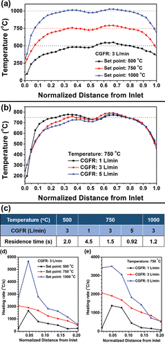
To better understand the heating conditions in the system, the temperature along the centerline of the quartz tube and immediately downstream of the filter was measured within the heated range (81.3 cm) by a K-type thermocouple. Distilled water was atomized as a surrogate for the precursor during the measurement. N2 gas was used as the carrier gas, the same as during the actual particle generation process. The temperature profiles and residence time are given in . The procedures for the estimation of residence time are provided in the online supplementary information (SI), Section 1.
Mechanism exploration
Conditions of high temperatures (500°C, 750°C, and 1000°C) and long residence times (≥0.92 s) were utilized to fabricate the Cu-Sn binary powders, as discussed in the previous section. To investigate the mechanism of the particle formation process, experiments were conducted at lower temperatures and shorter residence times to identify reaction intermediates. The precursor contained 1 M Cu(NO3)2, 0.1 M SnCl2, and 0.1 M HNO3. EG was added with a concentration of 5.9 M. The spray pyrolysis was conducted at i) 300°C with CGFR = 5 L/min and quench gas at ∼5.2 L/min; and ii) 500°C with CGFR = 10 L/min and quench gas at ∼10.8 L/min. During those two experiments, only a single furnace was used, and the residence time was less than 0.74 s in both cases.
Characterization and data analysis
Scanning electron microscopy (SEM, Hitachi SU-70, Hitachi, Tokyo, Japan) was used to observe the particle morphologies. Transmission electron microscopy (TEM, Jeol Jem 2100 LaB6, Jeol Jem, Tokyo, Japan) was utilized to understand the details of the particle structures. Before conducting the SEM and TEM observations, powders were suspended in ethanol. After sonication for ∼1 min, the mixture was added dropwise onto a silicon wafer or TEM grid, and dried under ambient conditions. X-ray diffractometer (XRD, Bruker D8 advance, Bruker, Billerica, MA, USA) was used to obtain crystallographic information of powders. Particles were also examined by X-ray photoelectron spectroscopy (XPS, Kratos Axis 165, Kratos Axis, Manchester, UK) to determine the elemental distribution on the powder surface. In addition, the powders were sputtered in vacuum by argon ions for 20 min to collect the sub-surface concentration profile. The sputtering gun was set at 4 kV and 5 mA.
Results and discussion
Reaction temperature
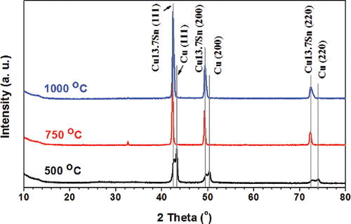
To identify the composition of the products, powder XRD with Cu Kα radiation was utilized, as shown in . When the set point of the furnaces was 500°C, Cu and Cu13.7Sn were the main phases. The residence time of the process was 2 s. When the temperature increased to 750°C, the residence time of the process was 1.5 s. Powders displayed higher quality crystallinity with sharp peaks of Cu13.7Sn without Cu peaks. However, there was one peak at 32.6°, which could not be identified as Cu or Cu13.7Sn. It may be attributed to intermediate salt phase(s) of small quantity, with low peak intensity compared to the major Cu13.7Sn peaks. The increase of temperature could promote the forming of a Cu-Sn solid solution, which is thermodynamically favorable. A similar phenomenon has also been reported in other alloy particles that a particle composed of a single alloy phase will have lower free energy compared to a particle containing multiple phases (Zhong et al. Citation2012a). When the temperature was increased to 1000°C, the residence time was 1.2 s. The intensity of the unidentified peak (32.6°) was negligible compared to the strong peaks of Cu13.7Sn. The XRD diagram exhibited high quality crystallinity with Fm-3m symmetry, implying complete reaction to generate Cu13.7Sn particles.
Figure 2. XRD results of powders generated from systematic conditions. The precursor contained 1 M Cu(NO3)2, 0.1 M SnCl2, 0.1 M HNO3, and 4.8 M EG. The CGFR was fixed at 3 L/min. The powders were generated at 500°C, 750°C, and 1000°C. The major peaks are from Cu13.7Sn (ICDD with PDF No. 03-065-6821) and Cu (ICDD PDF No. 01-070-3038).
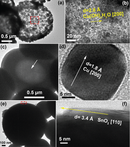
The morphologies of particles generated at different reaction temperatures with 4.8 M EG in the precursor are shown in with additional images in Figure S4 (SI). When the temperature was set at 500°C, hollow porous particles could be seen with primary particles (marked by solid line circle) on the surface, as shown in . The number mean diameter of the hollow porous particles and the primary particles are 1.5 μm and 150 nm, respectively (). The TEM observations of these particles further validate the porous hollow structure with primary particles scattered within the shell, as shown in .
Figure 3. SEM images of powders generated from the precursor solution with 1 M Cu(NO3)2, 0.1 M SnCl2, 0.1 M HNO3, and 4.8 M EG. The reaction temperatures were 500°C (a), 750°C (b), and 1000°C (c). The CGFR was fixed at 3 L/min. Insets are higher magnification images of selected regions marked by solid arrows. The scale bars in all figures are 1 μm. (d) The summary of the diameter of the particles marked as 1, 2, and 3 in (a)–(c). Detailed size distributions for each condition can be found in Figure S5 (in the SI).
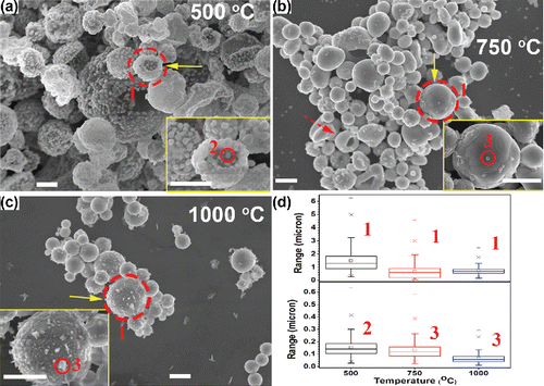
Figure 4. TEM images of particles fabricated by precursors with 1 M Cu(NO3)2, 0.1 M SnCl2, and 0.1 M HNO3. The CGFR was fixed at 3 L/min. (a)–(b) Particles generated at 500°C, with 5.9 M EG. (c)–(d) Particles obtained at 750°C, with 4.8 M EG. (e)–(f) Particles obtained at 1000°C, with 4.8 M EG.
According to reported results, the hollow structures were caused by a solute concentration gradient within the droplets which led to solute precipitation on the surface of the droplets (Gurav et al. Citation1993). The granular precipitates within the precursor droplets could concentrate on the droplet surface for the maximum structural stability during the solvent evaporation (Nandiyanto and Okuyama Citation2011). After the solvents vaporized and solutes reduced to metals, hollow porous particles were formed with primary particles comprising the shell (morphologies shown in ). Pressure may accumulate within the shell during evaporation of the solvent, leading the droplets to burst (Gurav et al. Citation1993). Thus, semi-spherical particles can be observed, as shown in the inset of .
When the furnace set point temperature was increased to 750°C, the amount of primary particles was significantly decreased. Instead, hollow particles with a crust on the surface can be seen in . The particles in the TEM image () also exhibit the hollow structure, with the dark part representing the crust and bright area (marked by white arrow) representing the hollow core. The number mean diameter of these particles is 0.68 μm (), which is smaller than that of the hollow porous particles generated at the 500°C. The decrease of the number mean diameter supports the hypothesis that the hollow crusted particles in are caused by the coagulation of the primary particles and shrinking of the hollow porous structure in . Size can affect the melting point of Cu and Sn (Ju et al. Citation2015; Karabacak et al. Citation2006). The reported melting point of bulk tin is ∼230°C (Ju et al. Citation2015; Wronski Citation1967). The melting of bulk Cu-Sn alloy ranges from 1085°C (Sn at % = 0) to 945°C (Sn at % = 10%) (Saunders and Miodownik Citation1990). Copper nanorods with a length of 2.3 μm and a diameter of 100 nm have also been found to melt below 550°C (Karabacak et al. Citation2006). The fragmented spherical particles may stem from the melting of the fragmented hollow particles (inset of ) obtained at 500°C. Thus, other morphologies, e.g., spherical particles with pores (inset of Figure S3d in the SI) and fragments (marked by a dashed arrow in , and circled by dashed lines in Figure S4c of the SI) were seen at this temperature, which indicates these particles may stem from the coagulation of the primary particles in . Based on and S4 (in the SI), it can be concluded that the morphologies of particles at 750°C showed the evolution from hollow to solid. The hollow to solid transition occurred between 500°C and 1000°C. In spray pyrolysis, reaction temperature is a critical factor influencing the particle structure. With the increase of temperature, particle structure could evolve either from hollow to solid (Ortega et al. Citation1991) or from solid to hollow (Eslamian and Ashgriz Citation2006) based on the chemical properties and precipitation rates of the salts in the precursor (Eslamian and Ashgriz Citation2006). In our system, the evaporation of HNO3 (Pvap, HNO3 = 172 kPa at 373 K) from precursor droplet into the gas phase promotes hydrolysis of SnCl2 (Yaws Citation1995). Based on the prior reports, SnCl2 prefers to hydrolyze to form hydroxides and decompose to SnO, even at room temperature (Cohen and West Citation1972; Perry Citation2011). SnO is likely formed at the droplet surface. Thus, with the increase of reaction temperature, the Cu-Sn particles shifted from hollow to solid due to the melting of the primary particles and densification of the Cu-Sn particles. This mechanism may also be applicable to other systems with rapidly precipitating components.
Small particles can be seen on the surface of the hollow crusted particles at 750°C (inset of , solid line circle). The small particles, with number mean diameter of 0.13 μm (), were believed to form by gas-to-particle conversion, which has been reported in spray pyrolysis (Fotou et al. Citation2000; Tsai et al. Citation2004; Schulz et al. Citation2005). One possible formation mechanism is that the volatized Cu(NO3)2 vaporizes into the gas once it has precipitated from the solvent. The vapor pressure of Cu(NO3)2 at 495.8 K is 480 Pa (Addison and Hathaway Citation1958). Cu(NO3)2 may vaporize below 500 K and decompose to CuO, NO2, and O2 above 500 K (Stern Citation1972). CuO may nucleate into small oxide particles in the gas phase. With the reducing environment created by EG, it is rational to believe the CuO will be reduced to Cu, and then the small particles, as shown in , were formed. For reference, the vapor pressures of CuO and SnO at 1000°C are Pvap,CuO = 1.1 × 10⁻² Pa (Mack et al. Citation1923) and Pvap,SnO = 370 Pa (Platteeuw and Meyer Citation1956) and the vapor pressures of the pure metals are even lower, Pvap,Sn = 1.5 × 10⁻² Pa and Pvap,Cu = 6.0 × 10⁻³ Pa, at 1000°C (Gale and Totemeier Citation2003). Another possible mechanism is that after the solvent in the precursor droplets evaporated, the Cu and Sn may be reduced by the EG. The metals in the particles would vaporize, nucleate, and grow into particles with a diameter less than 100 nm in the gas phase. A similar mechanism has also been reported by other researchers (Tsai et al. Citation2004). In the TEM observation, the small particles were found to be pure Cu particles (), which further validated the hypothesis that the small particles are likely generated by gas-to-particle conversion.
When the temperature was increased to 1000°C, the particles underwent further densification to form spherical solid particles () with a number mean diameter of 0.71 μm (). The TEM image () also provides evidence of this conclusion. Small particles are still seen with number mean diameter of 0.13 μm on the particle surfaces, which are also believed to be formed by gas-to-particle conversion. The SnO2 seen in is believed to be caused by the oxidation of the Sn on the particle surface.
To further understand the elemental distributions and chemical states on and beneath the Cu-Sn particle surface, XPS analysis was utilized together with ion-beam sputtering. As shown in , the Cu/Sn ratio was lower on the surface (before sputtering) than under the surface (after sputtering). Both cases exhibited Sn enrichment compared to the Cu/Sn ratios in the precursor and the major crystal phase (Cu13.7Sn). In addition, the low temperature led to a lower Cu/Sn ratio than the high temperature. The detailed analysis of the chemical states within the particles by XPS also confirms the Sn enrichment on the surface, as discussed in Section 3 of the SI. This Sn enrichment on the particle surface is likely responsible for the difference in the Cu/Sn ratio observed from XRD measurements (13.7) compared to that in the precursor (10). A mass balance calculation was made assuming that the Cu-Sn particles were encapsulated by an amorphous Sn layer that would not appear in the XRD. From this calculation, the overall Cu/Sn ratio in the product particles is maintained at 10, if the ratio of the calculated thickness of Sn crust to the radius of Cu-Sn core (with Cu/Sn ratio = 13.7) is 0.008. Therefore, for particles obtained at 1000°C, with a mean diameter of 710 nm (Figure S5 in the SI), a thickness of 3 nm Sn enrichment layer would explain the Cu/Sn ratio observed with XRD. Thus, both the calculated and XPS results indicates that Sn accumulates on the particle surface ().
Figure 5. The Cu/Sn ratios summarized from XPS results (Section 3 in the SI). The precursor contained 1 M Cu(NO3)2, 0.1 M SnCl2, 0.1 M HNO3, and 4.8 M EG. The CGFR was set at 3 L/min. Sputtering was conducted in vacuum by argon ions for 20 min.
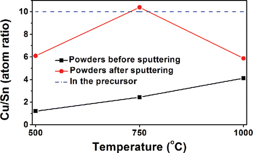
For a mixture of H2O and EG, the evaporation of H2O is faster than EG, because the vapor pressure of H2O is higher than EG (detailed vapor pressures are listed in Table S1 in the SI). Solutes would be expected to precipitate on the droplet surface with EG remaining as the inner core. During this process, a fast formation of SnO is possible because of the evaporation of HNO3 and hydrolysis of SnCl2 as discussed above. With the further evaporation of the solvent, copper salts would reach the saturation point and precipitate. Therefore, the Cu/Sn ratio was lower on the particle surface than beneath the surface, as shown in . It led to the concentration difference of Cu and Sn between the particle surface and inner core, which could provide the driving force for the diffusion of Cu towards the particle surface (DCu-in-Sn: 7.57 × 10⁻¹¹ m2/s, 220°C; DSn-in-Cu: 5.09 × 10⁻²⁴ m2/s, 220°C) (Mei et al. Citation1992). Therefore, the increase of reaction temperature could promote the diffusion of Cu towards the particle surface, causing the increasing Cu/Sn ratio on the particle surface, as seen in the XPS results in .
Residence time
To explore the effect of residence time on powder formation, spray pyrolysis was conducted at 750°C with various carrier gas flow rates (CGFRs). 750°C was chosen because it represented the transition conditions (as discussed in the temperature section), highlighting an observable difference in the morphology. The residence times were 4.5 s, 1.5 s, and 0.92 s for CGFR = 1, 3, and 5 L/min, respectively (). EG concentration was 4.8 M. As shown in , the morphologies of the particles varied under different residence times. The long residence time (4.5 s) promoted the generation of spherical particles with smooth surfaces (), which are at the lowest surface energy state. Few small particles were observed under this experimental condition. Short residence time (0.92 s) favored the formation of irregular shapes (e.g., pores on the particle surface, fragmented spherical particles, and lamellar fragments, marked by dashed arrows in ). The longer residence time may have led to the loss of small particles by thermophoretic deposition on the tube walls (Nguyen et al. Citation2002). Thus, small particles could not be seen on the filter (). The temperature difference between the centerline and wall position has been reported for similar gas flow rates, reactor tube dimensions, and furnace set point temperatures to range from 150°C to 200°C (Damour et al. Citation2005). Considering the mean particle sizes at 750°C (small particles: 79 nm, big particles: 630 nm, Figure S5 in the SI), the system is in the continuum regime and the thermophoretic velocity (ct) can be calculated as (Talbot et al. Citation1980):[1] where Cs (thermal slip coefficient), Ct (a numerical factor of order unity), and Cm (momentum exchange coefficient) are suggested to be 1.2, 2.2, and 1.1, respectively (Loyalka Citation1968; Talbot et al. Citation1980). For the radial temperature gradient, dT/dr = 16,000 K/m, when the temperature difference between the center line and tube wall was assumed to be 150°C. Other parameters of v (kinematic viscosity), lp (mean free path), and kg/kp (thermal conductivity ratio of gas to particle) are 3.7 × 10⁻⁵ m2/s, 0.14 nm, and 2 × 10⁻⁴, respectively (Yaws Citation1999). Based on the mean diameter of particles and small particles at 750°C, C (slip correction factor) are 1.3 and 5.0, respectively in each case (Friedlander Citation2000). By Equation (Equation1
[1] ), the thermophoretic velocities of large particles and small particles are 4.0 × 10⁻³ mm/s and 0.15 mm/s, respectively. Therefore, the difference between the thermophoretic velocities of big and small particles could cause the results observed in .
Figure 6. SEM images of powders obtained at 750°C from precursors with 1 M Cu(NO3)2, 0.1 M SnCl2, 0.1 M HNO3, and 4.8 M EG. The residence times are: 4.5 s (a), 1.5 s (b), and 0.92 s (c). The insets of each figure are higher magnification images of the area marked by arrows. Arrows show irregular structures. (d) The XRD results of the powders obtained at the conditions of (a)–(c). The peaks are attributed to Cu13.7Sn (ICDD with PDF No. 03-065-6821). All scale bars in the SEM images are 1 μm.
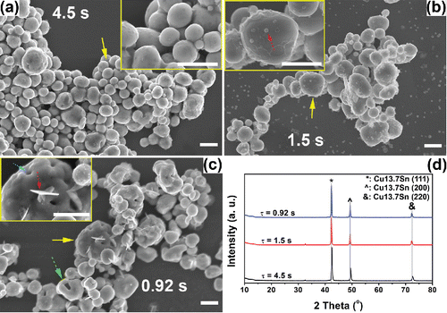
For the situation where residence time was short, particles had insufficient time to form spheres. Lamellar structures (inset of ) can be seen, which may have originated from metal hydroxide intermediates (Zhong et al. Citation2012b). Pores on the surface of the particles were formed as a result of the rapid evaporation caused by the short residence time. The powders generated at medium residence time (1.5 s) exhibited an intermediate morphology between the long (4.5 s) and short (0.92 s) residence time conditions.
To further understand the effect of residence time on the crystallinity of Cu-Sn binary particles, XRD measurement was performed. As shown in , there was no significant difference in crystal structure among particles fabricated at different residence times. All samples exhibited high quality crystallinity with sharp Cu13.7Sn peaks, similar to the powders generated at other conditions. The small peaks around 32.6° are still believed to be unidentified intermediate(s) as discussed previously.
Effects of quench
As discussed previously, Cu and Sn were thought to evaporate into the carrier gas in the heated zone. Gas-to-particle conversion may lead to small particles after the carrier gas was cooled by the quench gas. To validate this hypothesis, a control experiment was designed, and conducted at the same conditions following the same procedures, except no quench gas was introduced. Thus, the temperature at the filter increased from 105°C (with quench) to 175°C (without quench). The cooling rate decreased from 162°C/s (with quench) to 66°C/s (without quench). To better investigate the effect of quench on the products, SnCl2 concentration was set to 0.05 and 0.1 M in the precursor to investigate the origin of the small particles. The concentrations of Cu(NO3)2 and EG were still kept at 1 M and 4.8 M in both cases, respectively. During spray pyrolysis, the set point of the furnaces was 750°C. The residence time was 1.5 s.
As shown in , powders generated with quench gas displayed a large quantity of small particles (marked by arrows). Without quench gas, the amount of small particles decreased significantly (). This observation supports the hypothesis that small particles originated from gas-to-particle conversion, since increase the cooling rate (by introducing quench) would enhance the homogeneous and heterogeneous nucleation (Schulz et al. Citation2005). In addition, sharp edges can be observed on the particle surface, as shown in , marked by arrows. These flat structures were attributed to the {111} facets of copper, indicating the doping of other elements (Chatain et al. Citation2004). From , the amount of small particles did not change significantly. Together with , it could be concluded that the copper species may be the main source for the small particles instead of tin species.
Figure 7. The effect of quench gas on the morphologies and crystallinities of the powders obtained at 1000°C. The precursors contained 1 M Cu(NO3)2, 0.1 M HNO3, and 4.8 M EG. The SnCl2 concentration was 0.05 M (a)–(b) and 0.1 M (c)–(d). SEM images of the prepared powders are shown in (a), (c) with quench gas, and (b), (d) without quench gas. (e) The XRD results of the generated powders at the four conditions. Standard peaks from Cu13.7Sn, (Cu32Sn) 0.12, and Cu are displayed below the XRD results for reference. Scale bars in the SEM images are 1 μm.
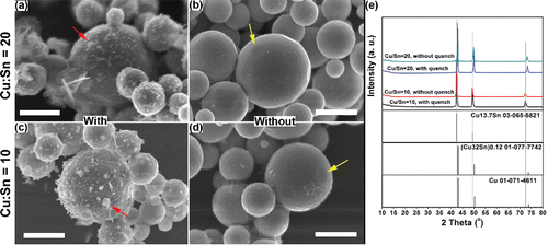
The powders generated from the four experimental conditions mentioned above were also characterized by XRD to explore the effect of quench on the final particle crystallinity. The products fabricated by precursors with 0.1 M SnCl2 exhibited Cu13.7Sn as the major peaks (). For products fabricated from precursors of 0.05 M SnCl2, the peaks were also sharp () with positions close to those of Cu13.7Sn. However, the peaks were also close to other two standard peaks in the ICDD database. The standard peaks of the possible candidates are presented below the XRD diagram in . It seems that the different input Cu/Sn ratio in the precursor may lead to the formation of solid solutions other than Cu13.7Sn in the products. Therefore, intermediate products, i.e., (Cu32Sn)0.12 and Cu matrix were seen in the XRD results. In addition, there was no significant difference between the XRD results of the samples generated at the same SnCl2 concentration with or without quench.
Mechanism
After understanding how temperature, residence time, quench gas, and EG concentration (Section 2 in the SI) affect the powder morphology, crystallinity, and elemental distribution, the mechanism of Cu-Sn binary particle formation was investigated from two perspectives: chemical reaction steps and structural progression. To explore the chemical process of Cu-Sn binary particles generation from the precursor, two conditions were chosen at low temperature and low residence time to identify reaction intermediates. 300°C was chosen because the initial decomposition temperature of EG is ∼240°C (Yue et al. Citation2012). As the droplets have not fully evaporated in this condition, the crystallinity of the powder was poor with an obvious amorphous background in the XRD diagram (Figure S9 in the SI), compared to previous XRD results. The peaks in the Figure S9 (in the SI) were attributed to metal hydroxide salts (Cu2Cl(OH)3 and SnCl2(H2O)2) and metal (Sn).
To further explore the particle formation process, the temperature was increased to 500°C and the CGFR was increased to 10 L/min to keep the residence time less than 0.74 s. As shown in Figure S10 (in the SI), the samples generated from 500°C consisted of metal hydroxide salts (Cu2Cl(OH)3 and Cu2(NO3)(OH)3), metal oxides (Cu2O and CuO), and solid solutions (Cu13.7Sn). Based on the discussion above, it is proposed that the spray pyrolysis process of converting precursor to Cu-Sn binary particles is composed of the following chemical reaction steps.
Hydrolysis of the salts
With the increase of temperature within the droplets ( and ) and the relative solute concentration (caused by the solvent evaporation), metal salts gradually hydrolyze to hydroxides (Cohen and West Citation1972; Munnik et al. Citation2011). Thus, the possible reactions are:
[2]
These products were observed in Figure S9 and S10 (in the SI). CuCl2 may be formed from ion exchange, which is possible for the lower solubility of CuCl2 (43.8 g in 100 g H2O) compared to Cu(NO3)2 (60.1 g in 100 g H2O) (Perry Citation2011). CuCl2 may also hydrolyze in a similar way.
This product phase was observed in Figure S9 (SI).
Formation of metal oxides
With the further increase of temperature, the hydroxides begin to decompose to oxides:
Similar results have also been reported (Cohen and West Citation1972; Munnik et al. Citation2011). CuO was detected in XRD measurements (Figure S10 in the SI).
Reduction of the metal oxides to metals
As EG and N2 can create a reducing environment (Yue et al. Citation2012), metal oxides will finally be reduced to Cu and Sn. The evidence for the existence of copper and tin can be seen in the and Figure S9 (in the SI), respectively. Cu2O was detected in the XRD (Figure S10).
Diffusion of Sn to form a solid solution
Finally, the Sn will dissolve into the Cu crystal matrix to form the Cu-Sn solid solution. However, the solid solution formation would not be completed at low temperature such as 500°C. Therefore, both Cu and Cu13.7Sn phases were observed in the XRD diagram (). Based on Cu-Sn phase diagram, the phases in the Cu-Sn binary system with same Cu/Sn ratio at 500°C should be Cu and Cu3.73Sn (Miettinen Citation2008). The formation of Cu13.7Sn could be attributed to three causes: (i) The cooling effect caused by introducing quench gas could cause the product to be trapped in a nonequilibrium state; (ii) Cu and Cu13.7Sn share the same Fm-3m point group symmetry, with close lattice spacing (Cu: 3.625 Å; Cu13.7Sn: 3.688 Å) (Andresen Citation1958; Srinivasan and Anantharaman Citation1963); (iii) The accumulation of Sn on the particle surface may increase the Cu/Sn ratio in the bulk compared to the Cu/Sn ratio in the precursor (10). Cu13.7Sn is a stable phase with Cu/Sn ratio higher and close to 10 (Chatterjee and Gupta Citation1975). When the set point of the furnaces was 750°C, the increased temperature would promote the formation of Cu-Sn solid solution. Thus, only Cu13.7Sn was observed in . When the temperature was further increased to 1000°C, the high temperature would lead to the system in the liquid state (Booth et al. Citation1977), implying facile diffusion of tin into copper matrix to form the Cu13.7Sn phases. Therefore, Cu13.7Sn was found in . Peaks in were also belonged to Cu13.7Sn for the same reasons.
A general mechanism has been proposed to explain the particle formation in spray pyrolysis using multi-source precursors (Gurav et al. Citation1993). Applying this mechanism to our specific Cu-Sn system, hydrolysis of SnCl2 may lead to the precipitation of SnO in the droplets before precipitation of Cu(NO3)2. The formation of Cu-Sn particles involves a structural evolution from granular precipitates to a dense solid solution of Cu-Sn. The detailed process can be summarized as follows, together with the schematic illustration presented in :
Precipitation on the droplet surfaces: After the precursor droplets were carried into the furnaces, rapid evaporation of HNO3 and solvents, particularly H2O (due to a higher vapor pressure than EG) (Yue et al. Citation2012; Speight Citation2004), would occur. It could assist the hydrolysis of tin salts, forming the precipitates (Perry Citation2011), as well as generate a concentration gradient of the dissolved solutes within the droplets. Precipitation will readily occur when the solute concentration reaches the saturation point. Thus, droplets with primary particle shells and liquid EG cores would take shape.
Figure 8. Schematic illustration of the proposed Cu-Sn binary particle formation process. The circle in Step (Equation1
![Figure 8. Schematic illustration of the proposed Cu-Sn binary particle formation process. The circle in Step (Equation1[1] ) represents the precursor droplet. The magnified image of the Step (Equation1[1] ) product illustrate the Cu-Sn solid solution and the metallic copper, respectively. The small circles are the metal particles formed by gas-to-particle conversion.](/cms/asset/e665d6c7-4b6a-4f89-b3b3-b73172b108f8/uast_a_1265912_f0008_oc.gif)
The reduction of precipitates to metals occurs by reaction with EG. The magnified image of the Step 1 product (), represents the Cu-Sn solid solution and the metallic copper. These substances were both found in XRD results at 500°C (). Once the solvents evaporate, hollow structures would be formed with primary particles comprising the shell (Step 2, ). If the process is ceased here, porous hollow particles would be generated (Step 3, ). The hollow porous structure has been observed in . In some cases, bursting of the droplets may occur due to the buildup of pressure caused by solvent evaporation (Gurav et al. Citation1993). Then fragmented, hollow, and porous particles can be found, as shown in the insets of .
Melting and shrinking of the hollow structure: After the hollow porous structure is generated, the primary particles will begin to sinter at the high temperatures. In the meantime, Sn may diffuse into the Cu matrix to form a solid solution (Step 3, ). Hollow structures with rough crusted shells would be fabricated if the process stops here, as shown in . Other structures, e.g., fragmented spherical particles (, marked by dashed arrow), could also be regarded as products of the interconnection of primary particles seen in the powders at 500°C (inset of ). In addition, the evaporation of solvent may cause pore formation on the particle surfaces (Figure S3d in the SI). Therefore, morphologies as shown in and Figure S3d-f (in the SI) can be seen once the process is stopped after the gas-to-particle conversion (Step 4, ).
Solidification: In the final step, solidification would be achieved once the residence time is long enough and temperature is high enough (Step 4, ). After being cooled by the quench, small particles could be generated by gas-to-particle conversion (Step 5, ). Thus, morphologies as shown in could be observed.
Micron-sized solid particles are favored for applications including conductive thick film pastes used for printing conductive lines and interference packaging (Huang and Sheen Citation1997; Wu et al. Citation2009). Based on our experimental results, high temperature (1000°C) and long residence time (4.5 s) promotes the formation of micron-sized solid Cu-Sn particles, a potential condition for the further real application. The accumulation layer of Sn on the particle surface may protect the particle from being oxidized. The exploration of Cu/Sn oxidation resistance and conductivity as a function of composition and processing environment is the subject of further exploration by our group.
Conclusions
Cu-Sn binary particles were fabricated by spray pyrolysis with EG as the co-solvent and reducing agent. By tuning the temperature, residence time, and quench gas flow rate, particles could be generated with controllable morphologies, crystallinities, and elemental distributions, which may broaden the further application of Cu-Sn bimetallic particles. Hollow porous particles were generated at 500°C, with primary particles comprising the surface. The existence of Cu and Cu13.7Sn indicated that the generation of Cu-Sn binary particles may be incomplete at 500°C. Cu13.7Sn phase was formed because of the cooling by introducing quench, the increased Cu/Sn ratio in the bulk caused by Sn enrichment on the particle surfaces, and the thermodynamic stability of Cu13.7Sn phase. With the increase of temperature, a transition occurred, causing the particle morphology to shift from hollow to solid, which has been validated by samples generated at 750°C. At 1000°C, solid particles could be generated with high quality crystallinity, and only Cu13.7Sn peaks were present in the XRD diagram. The Cu/Sn ratio was further increased on the particle surface at 1000°C. The small particles were likely formed likely via gas-to-particle conversion.
The residence time and quench gas flow rate mainly contributed to the morphological differences. At the condition where the residence time was 4.5 s, spherical particles with smooth surfaces were obtained. The increase of the CGFR decreased the residence time, leading to insufficient time for the thermophoretic deposition of small particles on the tube walls, which could significantly reduce the loss. Thus, small particles became observable when the residence time was 1.5 s. Particles with irregular morphologies were synthesized at the condition where residence time was 0.92 s. However, high quality crystallinity of Cu13.7Sn could be seen in all samples at 750°C regardless of the CGFR changes. The introduction of quench gas promoted the formation of small particles.
From the experimental results, the mechanism of Cu-Sn binary particle generation can be explained through two perspectives: chemical reaction steps and structural progression. Substances in the precursor were first hydrolyzed into hydroxides. Then the hydroxides decomposed into metal oxides. Subsequently, the metal oxides were reduced to metals, and a solid solution formed. For the structural evolution, precipitation of the solutes occurred during solvent evaporation of the precursor droplets. Thus, hollow structures could be generated. Finally, the shrinking of the hollow particles continued until solid particles were formed. The accumulation of Sn on the particle surfaces could protect Cu from being oxidized. In addition, the method of generating Cu-Sn binary particles combined with the investigation of the underlying mechanism provides a foundation for fabricating other bimetallic particles.
UAST_1265912_Supplemental_File.zip
Download Zip (2.1 MB)Acknowledgments
The authors gratefully acknowledge the assistance of Dr. Sz-Chian Liou (AIMLab) for TEM, Dr. Karen Gaskell for XPS and Dr. Peter Zavalij for XRD (Department of Chemistry & Biochemistry, University of Maryland). The authors acknowledge the support of the Maryland NanoCenter and its AIMLab.
Funding
This work was supported by National Science Foundation (CBET- 1336581) and by the DuPont Company. The authors declare no competing financial interest.
Related Research Data
References
- Addison, C. C., and Hathaway, B. J. (1958). 628. The Vapour Pressure of Anhydrous Copper Nitrate, and its Molecular Weight in the Vapour State. J. Chem. Soc. (Resumed), 3099–3106. DOI: 10.1039/JR9580003099
- Andresen, A. F. (1958). The Effect of Dissolved Tin on the Lattice Parameter of Copper. Trans. Amer. Inst. Min. Metallurg. Eng., 212:259–260.
- Booth, M. H., Brandon, J. K., Brizard, R. Y., Chieh, C., and Pearson, W. B. (1977). Gamma-Brasses with F Cells. Acta Crystallogr. Sect. B, 33:30–36.
- Cao, W., Li, W., Yin, R., and Zhou, W. (2014). Controlled Fabrication of Cu–Sn Core–Shell Nanoparticles via Displacement Reaction. Colloids Surf., A, 453:37–43.
- Chatain, D., Ghetta, V., and Wynblatt, P. (2004). Equilibrium Shape of Copper Crystals Grown on Sapphire. Interface Sci., 12:7–18.
- Chatterjee, S., and Gupta, M. (1975). Lattice Parameters of Some Binary and Ternary Copper Alloys. J. Appl. Crystallogr., 8:492–493.
- Chen, Z., Ye, S., Stewart, I. E., and Wiley, B. J. (2014). Copper Nanowire Networks with Transparent Oxide Shells That Prevent Oxidation without Reducing Transmittance. ACS Nano., 8:9673–9679.
- Cho, E. C., Camargo, P. H. C., and Xia, Y. (2010). Synthesis and Characterization of Noble-Metal Nanostructures Containing Gold Nanorods in the Center. Adv. Mater., 22:744–748.
- Cohen, R. L. and West, K. W. (1972). Solution Chemistry and Colloid Formation in the Tin Chloride Sensitizing Process. J. Electrochem. Soc., 119:433–438.
- Damour, T. M., Ehrman, S. H., Karlsson, M. N. A., Karlsson, L. S., and Deppert, K. (2005). Experimental Evidence for Nonuniform Flow in a Horizontal Evaporation/Condensation Aerosol Generator. Aerosol Sci. Technol., 39:444–451.
- Deshpande, V., Kshirsagar, A., Rane, S., Seth, T., Phatak, G. J., Mulik, U. P., and Amalnerkar, D. P. (2005). Properties of Lead-free Conductive Thick Films of Co-precipitated Silver–Palladium Powders. Mater. Chem. Phys., 93:320–324.
- Dhas, N. A., Raj, C. P., and Gedanken, A. (1998). Synthesis, Characterization, and Properties of Metallic Copper Nanoparticles. Chem. Mater., 10:1446–1452.
- Eslamian, M. and Ashgriz, N. (2006). Effect of Precursor, Ambient Pressure, and Temperature on the Morphology, Crystallinity, and Decomposition of Powders Prepared by Spray Pyrolysis and Drying. Powder Technol., 167:149–159.
- Fievet, F., Fievet-Vincent, F., Lagier, J.-P., Dumont, B., and Figlarz, M. (1993). Controlled Nucleation and Growth of Micrometre-size Copper Particles Prepared by the Polyol Process. J. Mater. Chem., 3:627–632.
- Fotou, G. P., Kodas, T. T., and Anderson, B. (2000). Coating Titania Aerosol Particles with ZrO2, Al2O3/ZrO2 and SiO2/ZrO2 in a Gas-Phase Process. Aerosol Sci. Technol., 33:557–571.
- Friedlander, S. K. (2000). Smoke, Dust, and Haze. Oxford University Press, New York.
- Fujimoto, T., Terauchi, S., Umehara, H., Kojima, I., and Henderson, W. (2001). Sonochemical Preparation of Single-Dispersion Metal Nanoparticles from Metal Salts. Chem. Mater., 13:1057–1060.
- Gale, W. F. and Totemeier, T. C. (2003). Smithells Metals Reference Book. Heinemann, Butterworth.
- Grouchko, M., Kamyshny, A., and Magdassi, S. (2009). Formation of Air-stable Copper-silver Core-shell Nanoparticles for Inkjet Printing. J. Mater. Chem., 19:3057–3062.
- Gurav, A., Kodas, T., Pluym, T., and Xiong, Y. (1993). Aerosol Processing of Materials. Aerosol Sci. Technol., 19:411–452.
- Gürmen, S., Stopić, S., and Friedrich, B. (2006). Synthesis of Nanosized Spherical Cobalt Powder by Ultrasonic Spray Pyrolysis. Mater. Res. Bull., 41:1882–1890.
- Huang, C.-Y. and Sheen, S. R. (1997). Synthesis of Nanocrystalline and Monodispersed Copper Particles of Uniform Spherical Shape. Mater. Lett., 30:357–361.
- Istratov, A. A., Flink, C., Hieslmair, H., McHugo, S. A., and Weber, E. R. (2000). Diffusion, Solubility and Gettering of Copper in Silicon. Mater. Sci. Eng. B—Adv., 72:99–104.
- Jo, Y. H., Park, J. C., Bang, J. U., Song, H., and Lee, H. M. (2011). New Synthesis Approach for Low Temperature Bimetallic Nanoparticles: Size and Composition Controlled Sn-Cu Nanoparticles. J. Nanosci. Nanotechnol., 11:1037–1041.
- Ju, Y., Tasaka, T., Yamauchi, H., and Nakagawa, T. (2015). Synthesis of Sn Nanoparticles and Their Size Effect on the Melting Point. Microsyst. Technol., 21:1849–1854.
- Karabacak, T., DeLuca, J. S., Wang, P.-I., TenEyck, G.A., Ye, D., Wang, G.-C., and Lu, T.-M. (2006). Low Temperature Melting of Copper Nanorod Arrays. J. Appl. Phys., 99:064304.
- Kim, H.-S., Lee, K.-H., and Kim, S.-G. (2006). Growth of Monodisperse Silver Nanoparticles in Polymer Matrix by Spray Pyrolysis. Aerosol Sci. Technol., 40:536–544.
- Kim, J. H., Babushok, V. I., Germer, T. A., Mulholland, G. W., and Ehrman, S. H. (2003). Cosolvent-assisted Spray Pyrolysis for the Generation of Metal Particles. J. Mater. Res., 18:1614–1622.
- Kim, J. H., Ehrman, S. H., and Germer, T. A. (2004). Influence of Particle Oxide Coating on Light Scattering by Submicron Metal Particles on Silicon Wafers. Appl. Phys. Lett., 84:1278–1280.
- Kim, S.-W., Kim, M., Lee, W. Y., and Hyeon, T. (2002). Fabrication of Hollow Palladium Spheres and Their Successful Application to the Recyclable Heterogeneous Catalyst for Suzuki Coupling Reactions. J. Am. Chem. Soc., 124:7642–7643.
- Kumar, K. S., Reinbold, L., Bower, A. F., and Chason, E. (2011). Plastic Deformation Processes in Cu/Sn Bimetallic Films. J. Mater. Res., 23:2916–2934.
- Lenggoro, I. W., Hata, T., Iskandar, F., Lunden, M. M., and Okuyama, K. (2000). An Experimental and Modeling Investigation of Particle Production by Spray Pyrolysis Using a Laminar Flow Aerosol Reactor. J. Mater. Res., 15:733–743.
- Li, Y., Wu, Y., and Ong, B. S. (2005). Facile Synthesis of Silver Nanoparticles Useful for Fabrication of High-Conductivity Elements for Printed Electronics. J. Am. Chem. Soc., 127:3266–3267.
- Lide, D. (2007–2008). CRC Handbook of Chemistry and Physics. CRC Press, New York.
- Liu, C. M., Liu, W. L., Chen, W. J., Hsieh, S. H., Tsai, T. K., and Yang, L. C. (2005). ITO as a Diffusion Barrier Between Si and Cu. J. Electrochem. Soc., 152:G234–G239.
- Liu, W. L., Chen, W. J., Tsai, T. K., Hsieh, S. H., and Liu, C. M. (2007). Effect of Tin-doped Indium Oxide Film as Capping Layer on the Agglomeration of Copper Film and the Appearance of Copper Silicide. Appl. Surf. Sci., 253:5516–5520.
- Loyalka, S. K. (1968). Momentum and Temperature‐Slip Coefficients with Arbitrary Accommodation at the Surface. J. Chem. Phys, 48:5432–5436.
- Lu, L., Shen, Y., Chen, X., Qian, L., and Lu, K. (2004). Ultrahigh Strength and High Electrical Conductivity in Copper. Science, 304:422–426.
- Mack, E., Osterhof, G. G., and Kraner, H. M. (1923). Vapor Pressure of Copper Oxide and of Copper. J. Am. Chem. Soc., 45:617–623.
- Mei, Z., Sunwoo, A. J., and Morris, J. W. (1992). Analysis of Low-temperature Intermetallic Growth in Copper-Tin Diffusion Couples. Metall. Trans. A, 23:857–864.
- Miettinen, J. (2008). Thermodynamic Description of the Cu–Fe–Sn System at the Cu–Fe Side. Calphad 32:500–505.
- Morinaga, H., Suyama, M., Nose, M., Verhaverbeke, S., and Ohmi, T. (1996). A Model for the Electrochemical Deposition and Removal of Metallic Impurities on Si Surfaces. IEICE T. Electron., E79C:343–362.
- Munnik, P., Wolters, M., Gabrielsson, A., Pollington, S. D., Headdock, G., Bitter, J. H., de Jongh, P. E., and de Jong, K. P. (2011). Copper Nitrate Redispersion To Arrive at Highly Active Silica-Supported Copper Catalysts. J. Phys. Chem., C115:14698–14706.
- Nandiyanto, A. B. D. and Okuyama, K. (2011). Progress in Developing Spray-drying Methods for the Production of Controlled Morphology Particles: From the Nanometer to Submicrometer Size Ranges. Adv. Powder Technol., 22:1–19.
- Nguyen, Q. T., Kidder Jr, J. N., and Ehrman, S. H. (2002). Hybrid Gas-to-particle Conversion and Chemical Vapor Deposition for the Production of Porous Alumina Films. Thin Solid Films, 410:42–52.
- Ortega, J., Kodas, T. T., Chadda, S., Smith, D. M., Ciftcioglu, M., and Brennan, J. E. (1991). Formation of Dense Barium Calcium Titanate (Ba0.86Ca0.14TiO3) Particles by Aerosol Decomposition. Chem. Mater., 3:746–751.
- Park, B. K., Jeong, S., Kim, D., Moon, J., Lim, S., and Kim, J. S. (2007). Synthesis and Size Control of Monodisperse Copper Nanoparticles by Polyol Method. J. Colloid Interf. Sci., 311:417–424.
- Perry, D. L. (2011). Handbook of inorganic compounds. CRC Press, Boca Raton, FL.
- Pingali, K. C., Rockstraw, D. A., Deng, S. (2005). Silver Nanoparticles from Ultrasonic Spray Pyrolysis of Aqueous Silver Nitrate. Aerosol Sci. Technol., 39:1010–1014.
- Platteeuw, J. C. and Meyer, G. (1956). The System Tin + Oxygen. Trans. Faraday Soc., 52:1066–1073.
- Pluym, T. C., Powell, Q. H., Gurav, A. S., Ward, T. L., Kodas, T. T., Wang, L. M., Glicksman, H. D. (1993). Solid Silver Particle Production by Spray Pyrolysis. J. Aerosol Sci., 24:383–392.
- Polat, D. B., Lu, J., Abouimrane, A., Keles, O., Amine, K. (2014). Nanocolumnar Structured Porous Cu-Sn Thin Film as Anode Material for Lithium-Ion Batteries. ACS Appl. Mater. Interfaces, 6:10877–10885.
- Saunders, N. and Miodownik, A. P. (1990). The Cu-Sn (Copper-Tin) System. Bulletin of Alloy Phase Diagrams, 11:278–287.
- Schulz, H., Mädler, L., Strobel, R., Jossen, R., Pratsinis, S. E., and Johannessen, T. (2005). Independent Control of Metal Cluster and Ceramic Particle Characteristics During One-step Synthesis of Pt/TiO2. J. Mater. Res., 20:2568–2577.
- Song, Y. L., Tsai, S. C., Chen, C. Y., Tseng, T. K., Tsai, C. S., Chen, J. W., and Yao, Y. D. (2004). Ultrasonic Spray Pyrolysis for Synthesis of Spherical Zirconia Particles. J. Am. Ceram. Soc., 87:1864–1871.
- Speight, J. (2004). Lange's Handbook of Chemistry. McGraw-Hill Professional, New York.
- Srinivasan, S. and Anantharaman, T. R. (1963). Accurate Evaluation of Lattice Parameters of Alpha-brasses. Curr. Sci., 32:262–263.
- Stern, K. H. (1972). High Temperature Properties and Decomposition of Inorganic Salts Part 3, Nitrates and Nitrites. J. Phys. Chem. Ref. Data, 1:747–772.
- Talbot, L., Cheng, R. K., Schefer, R. W., and Willis, D. R. (1980). Thermophoresis of Particles in a Heated Boundary Layer. J. Fluid Mech., 101:737–758.
- Talley, C. E., Jackson, J. B., Oubre, C., Grady, N. K., Hollars, C. W., Lane, S. M., Huser, T. R., Nordlander, P., and Halas, N. J. (2005). Surface-Enhanced Raman Scattering from Individual Au Nanoparticles and Nanoparticle Dimer Substrates. Nano Lett. 5:1569–1574.
- Tsai, S. C., Song, Y. L., Tsai, C. S., Yang, C. C., Chiu, W. Y., and Lin, H. M. (2004). Ultrasonic Spray Pyrolysis for Nanoparticles Synthesis. J. Mater. Sci., 39:3647–3657.
- Wronski, C. R. M. (1967). The Size Dependence of the Melting Point of Small Particles of Tin. Brit. J. Appl. Phys., 18:1731.
- Wu, S. P., Gao, R. Y., and Xu, L. H. (2009). Preparation of Micron-sized Flake Copper Powder for Base-Metal-Electrode Multi-layer Ceramic Capacitor. J. Mater. Process. Technol., 209:1129–1133.
- Xia, B., Lenggoro, I. W., and Okuyama, K. (2000). The Roles of Ammonia and Ammonium Bicarbonate in the Preparation of Nickel Particles from Nickel Chloride. J. Mater. Res., 15:2157–2166.
- Xia, B., Lenggoro, I. W., and Okuyama, K. (2001a). Preparation of Ni Particles by Ultrasonic Spray Pyrolysis of NiCl2·6H2O Precursor Containing Ammonia. J. Mater. Sci., 36:1701–1705.
- Xia, B., Lenggoro, I. W., and Okuyama, K. (2001b). Preparation of Nickel Powders by Spray Pyrolysis of Nickel Formate. J. Am. Ceram. Soc., 84:1425–1432.
- Xie, Y., Liang, Y., Chen, D., Wu, X., Dai, L., and Liu, Q. (2014). Vortical Superlattices in a Gold Nanorods' Self-assembled Monolayer. Nanoscale, 6:3064–3068.
- Yaws, C. L. (1995). Handbook of Vapor Pressure: Volume 4: Inorganic Compounds and Elements. Gulf Professional Publishing, Houtson, TX.
- Yaws, C. L. (1999). Chemical properties handbook. McGraw-Hill, New York, Houtson, TX.
- Youngil, L., Jun-rak, C., KwiJong, L., Nathan, E.S., and Donghoon, K. (2008). Large-scale Synthesis of Copper Nanoparticles by Chemically Controlled Reduction for Applications of Inkjet-printed Electronics. Nanotechnology, 19:415604.
- Yue, H., Zhao, Y., Ma, X., and Gong, J. (2012). Ethylene Glycol: Properties, Synthesis, and Applications. Chem. Soc. Rev., 41:4218–4244.
- Zhong, K., Peabody, G., Blankenhorn, E., Glicksman, H., and Ehrman, S. (2012a). A Spray Pyrolysis Approach for the Generation of Patchy Particles. Aerosol Sci. Technol., 47(2):i–v.
- Zhong, K., Peabody, G., Glicksman, H., and Ehrman, S. (2012b). Particle Generation by Cosolvent Spray Pyrolysis: Effects of Ethanol and Ethylene Glycol. J. Mater. Res., 27:2540–2550.