
ABSTRACT
Detection of bioaerosols is important in fields ranging from environmental health monitoring to biosurveillance, and current detector weaknesses have motivated the development of new technologies. In this work, a detector was built, which applies the principles of droplet microfluidics to bioaerosol detection. Droplet microfluidics is a subfield of microfluidics based on the creation of monodisperse microdroplets with compartmentalized reagents and supports enhanced assays and fluidic manipulations. The bioaerosol detector operates by aerodynamically focusing aerosols directly into these droplets to harness the benefits of the microreactor environment. A breadboard detector system, which consisted of an aerodynamic focusing lens, aerosol-focusing capillary, microfluidic droplet chip, and optical microscope, was constructed. Computational fluid dynamic simulations and Lagrangian particle tracking modeling were conducted to identify the optimal conditions for focusing. Preliminary experiments, where aerosols were deposited onto a solid substrate, demonstrated sub 200-µm spot diameters for aerodynamic diameters of 2–5 µm. Test aerosols were then generated, and collected into the microfluidic liquid interface on the chip as verified by microscopy. Recovery efficiency of the aerosols was dependent on aerosol size and ranged from about 27% to nearly 100%. Finally, to prove bioaerosol collection and detection, a droplet propidium iodide (PI) assay was performed: the system distinguished between E. coli and non-biological aerosols within 20 s. Overall, this work established the technique of direct collection of bioaerosols into a convenient droplet microfluidic platform for detection.
Copyright © 2017 The Johns Hopkins University Applied Physics Laboratory
EDITOR:
1. Introduction
Robust monitoring technologies for airborne microbes are crucial to mitigate the health effects posed by environmental and agricultural bioaerosols, and biowarfare attacks. Current detector technologies suffer from lengthy response time, low sensitivity, and expensive consumption of reagents, and these shortcomings compel the development of new detectors. Categories of detectors include fluorescence-based techniques that discriminate bioaerosols via online single-aerosol interrogation for pyridine nucleotides like NAD(P)H and riboflavin (e.g., UV-APS, WIBS, BioScout, etc.), and techniques where bioaerosols are collected and the microbes are subsequently assayed (Saari et al. Citation2013; Bhangar et al. Citation2014; Hernandez et al. Citation2016). Incorporating a microfluidic platform into a detector is attractive and can address current weaknesses; however, a challenge is the matter of effectively delivering bioaerosols into the liquid of a microfluidic chip for assay (DeMello Citation2006; Mairhofer et al. Citation2009; Sackmann et al. Citation2014). The metric, concentration rate (Rc), reflects the ability of a detector to concentrate aerosols into a liquid volume, V, and is defined by Equation (Equation1[1] ):
[1] where Qs is the sampling flow rate of the system and η is the collection efficiency (Han and Mainelis Citation2008). In designing a system, concentration rate should be optimized by increasing the air flow rate and collection efficiency, or decreasing the volume of capture liquid preferably to microfluidic volumes, because this improves the aerosol detection sensitivity. Past studies reconciling microfluidics with aerosol collection (by deposition of aerosol in channels/half-channels) have reported concentration rates of 104–106 min−1, and have delineated the limitations with these approaches (Han and Mainelis Citation2008; Han et al. Citation2010, Citation2011; Jing et al. Citation2013, Citation2014; Novosselov et al. Citation2014; Pardon et al. Citation2015; Han et al. Citation2015a,Citationb; Foat et al. Citation2016; Ma et al. Citation2016). These studies have shown successes, but require further work in integration with assay platforms, clearly demonstrating end-to-end bioaerosol collection and identification, estimating limits of detection, and detailed field testing.
Within the realm of bioaerosol detection, droplet microfluidics, an emerging subfield of microfluidics, has remained unexplored. Unlike traditional microfluidics wherein a single liquid phase is used for transport and assay, droplet microfluidics is concerned with creation of discrete microdroplets in a carrier phase for compartmentalizing a bioanalyte with assay reagents (Teh et al. Citation2008). The interfaces of the droplets prevent crosstalk and allow each droplet to act as a microreactor for studying single analyte particles using techniques like immunoassays, PCR, and sequencing; these techniques have been recently translated for application in droplets (Nakano et al. Citation2005; Ottesen et al. Citation2006; Klostranec et al. Citation2007). Common droplet-creating schemes passively rely on the geometry of the channels and produce meta-stable monodisperse droplets with volumes ranging from picoliters to nanoliters (Anna et al. Citation2003). The minute droplet sizes (<50 µm) and monodispersity obtained with droplet microfluidics are not achievable by traditional droplet creation processes. With this droplet microreactor environment, sample volumes are reduced, assay sensitivity is improved, and detection thresholds can be reached more rapidly (Anna et al. Citation2003; Guo et al. Citation2012). In extending this concept for bioaerosol detection—via precision impingement of aerosols into these droplets—concentration rates in excess 106 min−1 are obtainable, assuming modest collection efficiencies and sampling airflow rates.
To harness the virtues of droplet microfluidics, this work proposed development of a new detector which operated by aerodynamically focusing bioaerosols directly into microfluidic droplets. outlines the principle of the detector. In Stage 1, an aqueous droplet containing compartmentalized reagents is created in a carrier phase on a microfluidic droplet chip (see inset). The droplet is then shuttled in the microchannel to a region, which is interfaced to the aerosol-laden air stream, and bioaerosols are precisely focused (encapsulated) into the droplet (Stage 2). Assay reagents, such as labeled antibodies or PCR reagents, then react with the target species during the incubation period in Stage 3. Optionally in this stage, a series of intermediate droplet manipulations can be performed depending on the type of assay employed. The target can be identified using an appropriate optical method or other technique. Key benefits of this droplet microfluidics approach in online detection include: an ability to map single aerosols to individual droplets, precisely tailored aerosol loading, immediate initiation of assay upon collection, and use of microelectronics-based droplet manipulations during collection.
Figure 1. Overview of the operating principle of the droplet-based microfluidics bioaerosol detector. In Stage 1, aqueous microfluidic droplets are created in an oil carrier phase in the channels of a microfluidic chip. Encapsulated in the droplets are reagents needed to perform an assay. A droplet is then moved to an opening in the channel directly across from the aerosol jet, and aerosols are focused toward the droplet interface. The aerosols are collected into the droplet (Stage 2), and are finally assayed using the detection technique of interest (Stage 3).
In realizing this concept, a breadboard detector was built, which consisted of an aerodynamic lens (ADL) for air-phase enrichment, a tapered focusing nozzle, a custom droplet microfluidic chip, and fluorescence microscope. Aerosol was converted into hydrosol by focusing aerosol into a pinned microfluidic air–liquid interface that was formed in the channel of the chip. Collection of test aerosols into the liquid interface was video recorded in real-time and elucidated the dynamics of aerosol collection. The overall concept of the detector was then proved by completing a droplet propidium iodide (PI) assay that distinguished between E. coli aerosols and non-biological aerosols. Overall, this work established the basis for direct collection of aerosols into microfluidic liquid interfaces in a lab-on-a-chip setting for the purpose of rapid bioaerosol detection.
2. Methods
2.1. Fabrication of the droplet microfluidics chip
A custom T-junction droplet chip was designed with aqueous and oil ports, and a main channel that had a depth of 190 µm and width of 390 µm. An overhead micrograph of the chip at the T-junction region is shown in the inset of . The aqueous and oil channels converge at a right angle at the T-junction, and with appropriate flow rates, produce aqueous droplets that are directed into the main channel. In contrast to conventional droplet chip designs, a vertical channel (hereafter referred to as the “detection channel”) was punched into the chip surface and connected to the main channel downstream of the T-junction; the hole would serve as the entry for aerosols into the detection channel (see rightmost inset in ). By positioning the aerosol focusing system over the chip, air pressure from the nozzle would pin the collection liquid emerging from the detection channel to form an air–liquid interface at the chip's top surface. The chip design allowed this collection interface direct access to aerosol-laden airflow while facilitating droplet manipulations following aerosol collection. A diameter of 177-µm was selected for the detection channel because this diameter could be easily created with a standard-gauge biopsy punch. The chip was constructed from polydimethylsiloxane (PDMS) by following the procedure described by McDonald and Whitesides (Citation2002).
Figure 2. Schematic of the breadboard detector system. A support was built to allow the aerodynamic lens (ADL) to cantilever over the chip, and a microscope was used to observe the aerosol collection phenomenon. The chip and aerosol focusing capillary cross-section is seen in the furthest right image.
2.2. Construction of the breadboard detector
displays the breadboard detector system. An inverted fluorescence microscope (Olympus, IX-70) was modified by removing the illuminator column and adding a cube filter. By illuminating the chip via a lamp underneath the stage, all the imaging components (illumination optics and objectives) were contained below the stage. The orientation removed obstructions from above the stage and allowed the aerosol focusing system to be positioned over the surface of the chip for aerosol delivery. Because fine 3D positioning of the nozzle was necessary for precision aerosol focusing toward the opening to the detection channel (i.e., detection hole), the ADL was attached to an XYZ translational optics stage. Manual adjustment of the stage, guided by observation with the microscope, gave reliable control of capillary positioning. The delivery line for test aerosol, which was attached to the top of the ADL, was composed of flexible tubing so the ADL could be translated during capillary positioning. In experiments, the prototype detector was operated as an open system for experimental convenience.
A commercialized version of the ADL described by Novosselov and Ariessohn (Citation2014) was used for its compatibility with the aerodynamic diameters associated with bioaerosols. An ADL is a passive technology consisting of a series of slits with orifices of decreasing size to successively focus and concentrate aerosols into an aerosol beam (minor flow). The ADL operated with major and minor flow rates of 8.5 sLPM and 1.5 sLPM, respectively. In accommodating the minor flow exit tubing, the ADL geometry caused the beam to spread into a square profile of 1.6 mm × 1.6 mm. Thus, although the aerosol flow was enriched, the aerosol beam exiting the ADL was defocused. Recollimating the beam was accomplished by adding a capillary with a tapered-accelerating nozzle downstream of the ADL. Tapered nozzles are often used to focus aerosol into lasers in particle counting instruments when tight aerosol beam tolerances are desired, but its use here was explored in a new application. As shown in Figure S1-1 in the online supplemental information (SI), the capillary was a hollow cylinder that tapered at 45° to a smaller inner diameter at its outlet. This tapering geometry imparts a radial velocity component directed toward the capillary centerline, effectively creating an aerosol focal point. The (red) lines in the rightmost image of denote the convergence of aerosol trajectories toward this focal point. Although more elegant solutions like sheath-flow focusing exist for precision focusing, the use of a tapered nozzle here was chosen for its simple adoption. Two nozzle inner diameters were evaluated in numerical simulations: 500 µm and 750 µm. High-resolution 3D printing was used to construct the capillary due to its ability to readily fabricate relatively complex 3D geometries and resolve sub-millimeter features. The design that could be practically fabricated with 3D-printing while offering adequate aerosol focusing (as predicted by numerical simulations) was then employed in experiments.
2.3. Computational fluid dynamics simulations and aerosol trajectory modeling
Computational Fluid Dynamics (CFD) simulations and Lagrangian aerosol trajectory modeling were completed to study aerosol focusing with the tapered nozzle and illustrate the practically obtainable deposition spot diameters. SolidWorks Flow Simulation was used to perform the modeling. Flow Simulation is a finite-volume CFD package, which uses immersed-body meshing to discretize the computational domain for solving the Navier–Stokes equations. In these simulations, an external flow analysis was conducted, but only the volume in the vicinity of the aerosol deposition (Figure S1-1 in the SI) was modeled because distant geometry negligibly affects the flow region of interest. Specifically, the focusing capillary itself and a 30 mm × 30 mm collection substrate (plate) were considered relevant geometry in the simulations. CFD simulations were completed for the following conditions: capillary inner diameters of 500 µm and 750 µm, inlet flow rates of 1 sLPM and 1.5 sLPM, and jet-to-plate distances (distance between the capillary outlet and substrate) of 0.5 mm, 1 mm, 2 mm, and 3 mm.
In the simulations, an adaptive meshing scheme was used to resolve velocity gradients near the capillary outlet. A grid independence study was performed, and the final total number of fluid control volumes in the domain exceeded 3 × 10⁵ in all simulations. Inspection of the mesh revealed that the mesh generator produced a refined mesh expected for a jet-impingement scenario. Given the fluid properties of air and characteristic dimension of the system (capillary outlet inner diameter), the maximum Reynolds number was approximately 3000; the flow field was solved using the package's modified k-ϵ model that is compatible with laminar, transitional, and turbulent flows (Lam and Bremhorst Citation1981). Varying the turbulence intensity and turbulence length parameters did not appear to have an appreciable effect on the results. For incompressible flows at low Mach Numbers, SolidWorks Flow Simulation combines a time-implicit approximation of the continuity, convection, and diffusion equations with an operator-splitting technique to address the pressure–velocity decoupling problem. A SIMPLE-type algorithm is used for solving the velocity and pressure fields. The reader is referred to the referenced document for further details concerning the numerical methods of Flow Simulation (Sobachkin and Dumnov Citation2014).
After finding the flow field, aerosol trajectory modeling was completed using a Lagrangian-particle tracking module. Aerosol trajectories were calculated for 1000 injected aerosols with aerodynamic diameters between 1 and 10 µm. In addition to determining deposition spot size, transmission efficiency of aerosols passing through the nozzle was calculated from the trajectory data. In aerosol impaction theory, aerosol collection is conventionally characterized as a function of the square root of the Stokes number (Stk1/2). In principle, aerosols with the same Stk1/2 will experience the same collection efficiency given the geometry of the system remains consistent. Stk is expressed in Equation (Equation2[2] ):
[2] where C, ρp, dp, Ut, µ, and d are the slip correction factor, particle density, physical particle diameter, air velocity at the nozzle throat, air viscosity, and jet-to-plate distance, respectively.
Besides the fine focusing that must be obtained, aerosols exiting the nozzle must be able to penetrate into the collection liquid upon impaction; the nozzle must accelerate aerosols to a sufficient velocity to overcome the surface tension of the liquid interface. For a non-wettable aerosol, the velocity component normal to the collection interface that is required for penetration, vn, is displayed in Equation (Equation3[3] ):
[3] where σ is the surface tension of the collection liquid (Rosinski Citation2000). The aerosol impaction velocities found from the simulations were compared to vn to roughly assess whether aerosols had attained the velocity necessary for collection.
2.4. Theory of pinning of a microfluidic interface by an air nozzle
At the top surface of the chip, an air–liquid interface must be formed in the detection hole, and this interface will be the target for aerosol deposition. Collection of the aerosols into the liquid depends on the creation of this stable interface. Physically, the liquid pinning phenomenon is manifested from a balance of forces between the stagnation air pressure from nozzle, interfacial forces, and internal liquid pressure in the channel. Evidently, the nozzle serves a dual purpose: aerodynamic focusing of aerosols and pinning the liquid interface for collection. displays the force balance on an aqueous droplet in a hydrophobic channel at the top of the detection channel. Foremost, with the dimensions of the microfluidic channel and properties of the fluids, gravity can be ignored as shown by calculation of the Bond number. For the following discussions, it is assumed that the pinned liquid interface near the surface of the chip is nearly stationary—this permits the droplet Capillary number, Cad (which is the ratio of viscous to interfacial terms), to be approximated as zero:[4] In Equation (Equation4
[4] ), µ is the larger viscosity between the constituents of the emulsion, Ud is the droplet velocity, and γ is the interfacial tension. The lubrication film, which is the oil layer encircling the droplet, has a thickness that scales according to
; thus, the lubrication film nearly vanishes for a stationary droplet.
Figure 3. (a) Cross-section of microfluidic chip and aerosol focusing capillary during pinning of the droplet. Approximate air streamlines are denoted with the solid black lines emerging from the aerosol nozzle. (b) Aerosol impaction into the droplet interface: is the particle velocity vector upon impaction with the droplet, and
is the velocity vector normal to the droplet interface upon impaction.

During droplet creation, it is assumed that oil is added into the chip before the aqueous solution, so that an oil layer resides above the first aqueous droplet. This oil leads the droplet train and forms an oil–air interface in the detection channel. Near the surface of the chip, a slight increase in the internal liquid pressure in the channel causes the oil to “shed” from the emulsion and adhere to the top surface of the chip. This allows the meta-stationary aqueous droplet to protrude from the hole and present an interface bordering the aerosol-laden air flow. Assuming the lubrication oil film is nearly removed, the force balance on the liquid interface can be treated as single-phase pinning whereby interfacial interactions between the aqueous and oil phases are not considered. Furthermore, it will be seen that the internal liquid pressure needed for droplet pinning of the aqueous phase necessitates bursting or shedding of the oil. The formulation described here then approximates both droplet and single-phase microfluidics pinning phenomena.
The following discussion adopts the theory developed by Cho et al. (Citation2007) for bursting of interfaces in abruptly diverging microfluidic channel geometry. In the initially partially evacuated detection channel, the pressure drop, ΔPe, across the air–liquid interface at equilibrium is described by the Young–Laplace equation shown in Equation (Equation5[5] ):
[5] Here, PL and P0 are the liquid pressure in the channel and air pressure on the interface, respectively, σ is the surface tension of the liquid, θe is the equilibrium contact angle, and D is the channel diameter. For an aqueous liquid in contact with a hydrophobic wall, an adequate liquid pressure must be supplied so that the meniscus can rise in the channel. According to contact line motion theory, this pressure must be sufficient to increase the contact angle to the critical advancing contact angle, θA, which is the contact angle related to the onset of meniscus motion. Hence, the following relationship describes the minimum pressure drop, ΔPa, for advancing the interface:
[6]
As the interface rises in the detection hole and moves vertically closer to the nozzle, it encounters a higher air pressure from the nozzle air jet. Near the surface of the chip, this air pressure, P0, can be approximated as the jet stagnation pressure, Pstag. Application of the Young–Laplace equation at the chip surface and rearranging accordingly yields the minimum liquid pressure, PL,min, needed for a stable collection interface:[7]
Upon reaching the surface of the chip (i.e., diverging geometry), the interface begins to form a contact angle with this horizontal surface, θn, that is defined as θn = θA −90°. This contact angle with the chip surface is less than the critical advancing contact angle and thus the interface halts and remains pinned at the surface by the air jet. Further advancement onto the chip surface (i.e., interface bursting) necessitates additional supplied liquid pressure to increase θn to θA.
When this condition is achieved, the new contact angle of the bulging interface with the channel walls, θI, becomes θI = θA + 90°. Interface bursting will also occur once θI exceeds 180°—even when θn is less than θA. Therefore, the contact angle associated with interface bursting and thus destruction of the pinning, , can be written as
. The pressure drop that initiates bursting can then be defined as in Equation (Equation8
[8] ):
[8]
Substituting the air-jet stagnation pressure, Pstag, for P0 into Equation (Equation8[8] ) and rearranging gives the liquid pressure at the onset of interface bursting:
[9] Therefore, collectively, the supplied liquid pressure must satisfy the criterion for the formation of a stable collection interface in the detection hole shown in Equation (Equation10
[10] ):
[10]
In modeling the droplet pinning phenomenon, the parameters θe (for water, air, and NovecTM PDMS coating), σ, and D were set to values of 105°, 0.07286 N/m, and 177 µm, respectively. The value of Pstag was obtained from the stagnation pressure found in the CFD simulations in this work. Alternatively, Pstag can be estimated using Bernoulli's equation for flow impinging on a plate:[11] provided Pstatic and V∞, the air pressure and velocity some distance upstream from the stagnation point, are known. Droplet bulging in the region between the chip surface and air nozzle can be initiated by increasing the liquid channel pressure or by reducing the air flow rate exiting the nozzle. From an aerosol collection perspective, protrusion of this interface closer to the nozzle alters the jet-to-droplet distance and correspondingly, the collection efficiency. Therefore, deliberate adjustment of the liquid pressure can modulate the collection efficiency of the system in situ. Although this has potential uses in a selective aerosol capture application, variations in liquid bulging were minimized in experiments to obtain reproducible results.
2.5. Experimental aerosol focusing onto a solid substrate
Experiments were first conducted to examine the focusing system's ability to precisely deposit aerosols into sub-millimeter dimensions. Test 2-µm, 3-µm, and 5-µm green fluorescent PSL aerosols were sent into the focusing system and impacted into a solid substrate, and the resulting spot diameter was inspected with fluorescence microscopy. The generation stand used to produce the test aerosol is described in S2 in the SI. The deposition phenomenon was recorded with an iPhone 4S attached to the microscope eyepiece. With the iPhone's nominal video frame rate of 14 frames/s and the aerosol concentrations tested, deposition of single aerosols onto the substrate surface could be resolved in real-time. Aerosol generation was terminated upon observing the deposition of 100 aerosols and the video was later analyzed for measurement of the deposition spot. The tests were completed for the three test particle sizes and jet-to-plate distances of 0.5 mm and 1 mm.
2.6. Aerosol collection into microfluidic air-liquid interface
Following the deposition experiments described above, capture of test PSL aerosol into the pinned liquid interface was performed. The microfluidic chip was prepared by purging the channels with acetone and then wiping the top surface of the chip with both acetone and ethanol. The chip was then secured to the microscope stage and the nozzle was aligned concentric to the detection hole via microscopy. After positioning, particle-free air was supplied to the focusing system at 1.5 sLPM, effectively creating an air stagnation point at the center of the empty detection hole. The collection liquid, 0.22-µm filtered deionized (DI) water, was then introduced into the aqueous inlet port of the chip using a pressure controller, and the water pressure was increased until a pinned water interface emerged from the detection channel. Only a single aqueous phase (i.e., non-emulsion) was used here to simplify tests. Once a stable liquid interface was observed for at least 30 s, video recording was started and test PSL were aerosolized for collection. Through trial and error, the collection period was varied from 10 s to 30 s to prevent overloading of the PSL particles in the collection liquid. After the collection period, a small volume of collection liquid was purged from the channel and shuttled onto the chip surface using air pressure from the nozzle. The purged liquid segment containing the collected PSL particles formed a droplet on the hydrophobic PDMS surface. Following evaporation, the PSLs contained in the interior of the coffee-ring deposit were imaged and enumerated using the cell-counting feature of IMAGEJ image processing software, Cell Counter. Cell Counter is an IMAGEJ plugin, which enables a user to manually count cells or particles in a micrograph image via a GUI (Girish and Vijayalakshmi Citation2004).
Upstream counts were determined by conducting separate trials where aerosols were impacted onto a greased PDMS substrate instead of into the liquid interface on the chip. The particles that deposited on the substrate again were counted using optical microscopy and IMAGEJ. Aerosol recovery efficiency, RE, was calculated from Equation (Equation12[12] ):
[12] where nc and nu are the number of particles counted from the collection liquid volume and number of particles exiting the capillary (i.e., upstream counts). Recovery efficiency represents the fraction of PSL that were collected and extracted after impingement, and is distinct from an aerosol collection efficiency. RE is essentially the product of aerosol collection efficiency and an extraction efficiency of particles from the chip, and RE will be lower than collection efficiency if particles adhere to the detection channel, for example. At least three trials were completed for each experimental condition (PSL sizes of 2 µm, 3 µm, and 5 µm and two jet-to-plate distances of 0.5 mm and 1 mm).
2.7. Droplet assay with propidium iodide (PI)
Using a droplet PI assay, the goal here was to show that the breadboard detector system could differentiate between biological and non-biological aerosols. Droplets containing PI were first prepared, and then dead E. coli and non-biological particles (dried lysogeny broth particles) were separately aerosolized and collected into the droplets. Because PI intercalates between DNA bases and enhances fluorescence by 20–30-fold for dead bacteria, the collected dead E. coli should yield a punctuated, bright fluorescence profile. On the other hand, background droplet fluorescence should be continually observed for collected non-biological particles. An aqueous PI solution of 10 µg/mL was chosen because this concentration has been shown to provide quality staining of bacteria cells (Yamaguchi and Nasu Citation1997). The aqueous PI solution was added into the aqueous-phase port of the chip and flowed with a solution of raindrop surfactant oil to create droplets at the T-junction having length of about 500 µm. After monodisperse droplets were being steadily generated, clean air was delivered to the aerosol focusing system and both aqueous and oil pressures were set at an appropriate pinning pressure. After observing stable pinning, aerosols were generated and collected into the droplet.
The E. coli suspension used for nebulization was prepared by first inoculating DH5-α E. coli cells in lysogeny broth (LB). After overnight incubation, a 25-mL aliquot was transferred to a glass beaker and the beaker was placed in a boiling water bath for E. coli inactivation. After 10 min, the beaker was removed from the water bath and the inactivation procedure was repeated for the blank LB control. For nebulization, 1 mL of the E. coli suspension or the control LB media was added to 30 mL DI water. After aerosol generation and collection for about 1 min, the collection droplet was kept pinned in the detection channel for PI incubation of 20 s. Droplets were then expelled from the detection hole, shuttled onto the chip surface using the air jet, and allowed to evaporate. Images of the droplets during various stages of evaporation were then compared.
3. Results and discussions
3.1. Computational fluid dynamics simulations and aerosol trajectory modeling
An example flow field in the region between the capillary outlet and plate is summarized in Figure S1-2 of the SI. Near the capillary outlet, air flow is gradually accelerated from the tapering inner diameter and the air jet produces a stagnation point on the substrate. Flow is then diverted away from the stagnation point, and during the expansion, weak recirculation zones are formed near the backward-facing step of the capillary tip. Analysis of the velocity vectors (S1-2a) indicated that flow adjacent to the tapering region of the capillary indeed angled toward the capillary centerline with an inward radial velocity magnitude over 30 m/s. Aerosol entrained in these streamlines therefore approach the collection substrate at a 45° angle after exiting the capillary.
Results from the Lagrangian trajectory modeling is shown in the panels in . Collection efficiency, the fraction of aerosols, which deposited on the substrate, was 100% for all simulations. and depict the deposition spot diameters for 500-µm and 750-µm diameter capillaries at 1.5 sLPM. Comparison of these two plots reveals that the deposition spread was tighter for 500 µm than for 750 µm, with the finest-focusing condition producing deposition spot diameters ranging from 30 to 260 µm. Both plots displayed relatively complicated features: there is a non-monotonic dependence on aerodynamic diameter and the curve shape is not consistent among the jet-to-plate distances. For all curves, the deposition spot is largest at 1 µm because low inertia aerosols follow the streamlines closely until impaction. The curves then decrease to their minimum values at aerodynamic diameters of 2–4 µm and this is followed by a gradual increase with aerodynamic diameter. The increase is because larger aerosols exit the capillary with high inertia and cannot adjust to the streamlines (i.e., radial accelerations) needed for focusing as readily as smaller aerosols. Thus, the larger aerosols are defocused and the size of their deposition spot approaches the inner diameter of the capillary outlet.
Figure 4. Summary of the Lagrangian particle tracking results. (a) Deposition spot size as function of jet-to-plate distance and aerodynamic diameter for the 500-µm capillary at 1.5 sLPM. (b) Deposition spot size for the 750-µm capillary at 1.5 sLPM. (c) Spot size vs. the Stk1/2 number for various conditions. Stk was calculated using jet-to-plate distance as the characteristic dimension. (d) Average aerosol velocity (normal to plate) upon impaction. These data were obtained from the injection of 1000 aerosols at the inlet plane of the focusing capillary in numerical simulations. The parameter Vn is the velocity magnitude that an aerosol must attain to penetrate into the droplet.
The difference in the shape of the curve for the 500-µm outlet, 2-mm condition () can be attributed to the positioning of the substrate relative to the focal point of the aerosol beam. The aerosol beam exiting from the capillary is characterized by a contraction region to the focal point followed by beam expansion region with slight variations arising from the presence of the substrate. Inspection of the aerosol trajectories during post-processing (figure not shown) indicated that the 1-mm distance coincided with the focal point, while for the 2-mm distance, the substrate was positioned well below the focal point and within the beam expansion region. Importantly, this finding revealed that an optimal jet-to-plate distance exists, and the jet-to-plate distance should be adjusted to the focal point of the aerosol beam. displays the spot diameter as a function of the Stk1/2. Focusing can be improved by appropriate positioning of the substrate for a given Stk1/2. The curves were found to collapse on each other for the same jet-to-plate distance. Calculating Stk1/2 with the outlet diameter as the characteristic dimension, conversely, yielded a plot that conveyed an unclear relationship between the curves. Again, the role of jet-to-plate distance in dictating aerosol focusing behavior is clearly emphasized here.
Finally, in , the normal velocity of aerosols impacting the substrate is shown. Except for 1 µm, the velocity attained is sufficiently higher than the velocity needed to penetrate the liquid interface, vn. The value vn represents the maximum theoretical velocity necessary for penetration, as it assumes a non-wettable aerosol impacting into a pure liquid. It is probable that 1-µm sized aerosols can be encapsulated in an aqueous detection droplet containing impurities like assay reagents or surfactants that lower the surface tension.
3.2. Experimental aerosol focusing into a solid substrate
Based on the numerical simulations, a 500-µm capillary was selected for experiments. However, high-resolution 3D printing failed to resolve the fine features of the design, and instead a capillary with inner diameter of about 600 µm was fabricated. The series of images in show the deposition profile of 100 green fluorescent PSL for various aerosol sizes and jet-to-plate distances using that capillary. Notably, the morphology of the deposition profile resembled a crescent or semicircle shape and was not circular or even symmetric as anticipated. Machining imperfections in the capillary from 3D printing could have introduced asymmetries in the radial velocity to produce this deposition profile. Because of this asymmetry, it was not trivial to quantify deposition spot area or diameter. To aid in a qualitative examination, two faint (red) circles have been superimposed on the images denoting diameters of 100 µm and 177 µm (i.e., diameter of detection channel).
Figure 5. Deposition spots obtained from experimental deposition of 100 fluorescent (green) PSL aerosols. The inner and outer faint (red) circles have diameters of 100 µm and 177 µm, respectively.
Relatively fine focusing was achieved, with most aerosols depositing within the 177-µm circle for each condition. The results were generally similar to the deposition diameters predicted by the 500-µm numerical simulations. For example, the simulation predicted a deposition spot diameter of about 150 µm for 3-µm aerosols and jet-to-plate distance of 0.5 mm, which was comparable to a Feret diameter of 190 µm for the spot found in experiments. The prevailing trends tended to agree with the numerical simulations as well: the 1-mm distance produced tighter focusing than 0.5 mm, and the 3-µm size was the most effectively focused size. Discrepancies between the simulated and experimental results were presumably due to the larger nozzle diameter of the 3D-printed capillary vs. the simulated capillary (600 µm to 500 µm), which would cause the experimental focusing to be poorer. Additionally, the inability of the k-ϵ turbulence model to resolve eddies in the transitional flow regime at the nozzle throat would produce an overprediction of focusing. Finally, the projected area diameter of the experimental spot, a metric that better characterizes an oblong deposition shape, would be more comparable to the simulated diameter.
3.3. Aerosol collection into microfluidic air-liquid interface
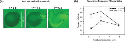
By carefully adjusting the liquid pressure supplied aqueous channel of the chip, a pinned air–liquid interface was stably formed at the chip surface. The measured minimum liquid pressure needed for pinning by the air jet (6.90 kPag) reasonably matched the theoretical prediction of Equation (Equation10[10] ) (7.80 kPag). shows an overhead view of the pinned air–liquid interface, which is seen as a dark, circular shape with diameter of 177 µm. The panels in are a visual time series of the pinned interface during generation of 3-µm PSL before aerosol loading, after 10 s of loading, and after 60 s of loading. At 10 s, the interface became brighter as captured PSL particles fluoresced in the liquid volume. Aerosols that missed the interface target (denoted by the dashed black circle) can be seen near the top right quadrant of the detection channel. Because the aerosol deposition profile was asymmetric and oblong, oftentimes it was not possible to aim the entire deposition profile within the circular interface target. At 60 s of aerosol loading, the overall image became noticeably brighter with loading of PSL particles both in the collection liquid and near the right edge of the hole to the detection channel. Note, that this video was recorded for demonstration purposes and the aerosol jet was intentionally misaligned to show aerosols missing the interface.
Figure 6. (a) Time series of fluorescent PSL aerosol capture into air–liquid interface (overhead view). The focal plane of the objective is at the top surface of the chip and aerosols are directed into the droplet from the capillary positioned above the chip in the configuration shown in . (b) The recovery efficiency of PSL aerosol collected at the air–liquid interface for jet-to-plate distances of 0.5 mm and 1 mm. The error bars represent standard error (the ratio of standard deviation to the square root of the number replicates) where the number of replicates is at least three.
A video of the aerosol collection process, which is available in S4 of the SI, confirmed that aerosols were indeed captured in the liquid. Following the start of PSL collection (at 00:10), individual particles can be seen swirling in the liquid vigorously and eventually agglomerating at higher loadings. It is hypothesized that the swirling behavior of liquid was caused by either shearing of the interface by the air jet or by the thermocapillary (Marangoni) effect. Evaporation at the interface by the air jet created a temperature gradient in the pinned liquid and a resulting surface tension gradient. The surface tension gradient possibly produced mass transfer and coherent, periodic circulation patterns in the pinned interface, which became visible following aerosol capture. The collected PSL essentially served as tracers to identify this phenomenon. For a droplet assay, the strong internal circulation of the collection liquid has the potentially beneficial effect of promoting mixing and improving assay kinetics. A dichotomy of microfluidics is that although its laminar flow characteristics enable precise fluid control, the lack of turbulence inhibits mixing and constrains biochemical reactions to the diffusion regime. The phenomenon observed here has desirable consequences because the mixing can possibly accelerate kinetics.
Recovery efficiency as a function of aerodynamic diameter is displayed in . Recovery efficiencies ranged from about 0.27 to 1 depending on aerodynamic diameter and jet-to-plate distance. As expected, the 1-mm distance had higher recovery efficiency for all sizes due to its finer focusing than at 0.5 mm. Aerosol sizes of 2 µm and 3 µm had efficiencies greater than 0.90 with the 1-mm jet-to-plate distance. The efficiency for 5 µm, however, was reduced to about 0.40 for both distances. According to the deposition spot size data in , most 5-µm aerosols deposited within a 177-µm circle that represented the liquid interface target, so inadequate focusing is likely not responsible for lower efficiency. It is possible that these higher-inertia aerosols are experiencing particle bounce at the interface or even at the PDMS surface after interface penetration. The modeled aerosol impaction velocities shown in indicate that aerosols attained velocities that exceeded critical bounce velocities reported in literature (Kuuluvainen et al. Citation2016). It must be noted, however, that bouncing is a complex phenomenon in this study because aerosols did not simply impact a surface and rebound; rather, aerosols penetrated the microfluidic liquid interface, were propelled through the liquid (which may have thickness of hundreds of microns), bounced on the PDMS channel, re-propelled through the liquid and the droplet interface, and reemerged as an aerosol. The critical velocities found in literature may not appropriately describe this phenomenon. Reaerosolization, caused by the vigorous swirling of the collection liquid, may also contribute to recovery losses. Previous studies investigating reaerosolization from impingers have suggested, however, that reaerosolization is dominant for lower inertia aerosols (Grinshpun et al. Citation1997).
The overall collection efficiency of the breadboard detector can be roughly estimated. Overall collection efficiency, η, is defined as the products of the transmission efficiencies through the ADL (ηt ADL) and focusing capillary (ηt FC), and the aerosol collection efficiency downstream of the focusing capillary. In this study, recovery efficiency (RE) approximated the collection efficiency downstream of the capillary, so η can be calculated as shown in Equation (Equation13[13] ):
[13]
Note, aspiration efficiency and losses in the transport tubing are neglected here. For the aerodynamic diameters of interest, ηt ADL is nearly 100% for the Novosselov and Ariessohn (Citation2014) ADL design, and this value was confirmed by the manufacturer of the ADL. Note that in their paper, the term was referred to as the collection efficiency of the ADL, with 100% indicating that enrichment of the aerosol concentration in the minor flow was the theoretical maximum (i.e., the ratio of the total flow rate to the minor flow rate). The transmission efficiency of the focusing capillary has been estimated in numerical simulations and the data are shown in Figure S3. The value of ηt FC ranged from about 80% at 2 µm to about 30% at 5 µm. Using the RE values shown in , η can then be calculated: η was about 74% at 2 µm and decreased to 12% at 5 µm for the 1-mm jet-to-plate distance. As expected, larger aerosols had lower overall collection efficiency due to poorer transmission through the focusing capillary and lower recovery efficiency. Optimizing the design of the system, particularly the aerosol focusing component, can improve these efficiencies.
Recall that to enumerate recovered PSL particles, liquid was purged from the detection channel and then sheared into a segment by an X-Y translation of the air jet. The resulting segment of liquid contained nearly all the captured particles, and coalesced into a droplet on the hydrophobic PDMS surface. These droplets, which were exposed to ambient conditions, had initial diameters of about 350 µm and evaporated while still retaining PSL particles. Continuous observation indicated that droplet evaporation was completed in about 30 s at 50% relative humidity. The convention of concentration rate can be applied to this dynamic process. Approximating η as 74% per the discussion in the previous paragraph, and using values of 10 LPM for Qs and 22.4 nL for V yields an Rc greater than 108 min−1, which increased with time due to the evaporating liquid volume. Eventually, the originally 350-µm droplet dried completely, resulting in concentration rates much greater than 108 min−1. An unforeseen result, this approach of allowing the collection droplet to dry (i.e., evaporation-mediated enrichment) can be exploited to enhance aerosol concentration rates in microdroplets.
3.4. Droplet assay with propidium iodide (PI)
Videos displaying real-time PI assay of collected E. coli and LB aerosols are included in the SI (S5). Selected images from those videos are displayed in . shows the fluorescence produced by the droplet that was loaded with LB aerosol; the fluorescence profile was uniform across the evaporated droplet silhouette. In contrast, as shown in , the E. coli-loaded droplet produced a profile with a punctuated fluorescence distribution. Each “dot” seen in the image was a collected E. coli cell that produced a bright, discrete fluorescence output. The areas surrounding the cells are notably darker because intercalation of PI molecules produced amplified fluorescence (documented to be a 20–30-fold increase) and also because PI had been scavenged by the cells. Interestingly, the videos of PI droplet evaporation showed a dynamic process in which the fluorescence of the cells relative to background progressed from (Equation1[1] ) minimal contrast to (Equation2
[2] ) high contrast and then (Equation3
[3] ) ultimately to less contrast. This progression possibly occurred because (Equation1
[1] ) dye uptake was initially incomplete, (Equation2
[2] ) evaporation of water in the droplet increased the PI concentration and enhanced uptake, and (Equation3
[3] ) finally because of the background fluorescence of PI residue overwhelmed the image. Ultimately, when designing an automated detection system, the dynamic behavior can be accounted for when droplets are interrogated.
Figure 7. PI droplet assay - fluorescence microscope imaging of droplets after 20 s of incubation for collection of (a) non-bioaerosols and (b) dead E. coli bioaerosols.
4. Conclusions
In this study, a droplet microfluidics-based bioaerosol detector was developed. The detector capitalized on the virtues of droplet microfluidics by precisely focusing aerosols into a microfluidic droplet containing compartmentalized assay reagents. A breadboard detector system consisting of an ADL, focusing capillary, custom microfluidic droplet chip, and optical microscope was constructed and tested. Numerical simulations of aerosol trajectories informed the design of the system and elucidated aerosol focusing physics. The tested aerosol focusing component achieved sub 200-µm deposition spot diameters for aerodynamic diameters of 2–5 µm. After obtaining precision aerosol focusing, a pinned air–liquid interface was established on the droplet chip, and aerosols were impinged into the microfluidic collection liquid. Real-time microscopic observation of the collection process confirmed aerosol capture in the interface—particles were observed to swirl rapidly in the collection liquid. Finally, a droplet PI assay was performed. The detector was able to distinguish between E. coli and non-biological aerosols collected in the droplet within 20 s of incubation.
This study developed the principles for the aerodynamic focusing and direct impingement of aerosols into pinned microfluidic droplets for the purpose of bioaerosol detection. Future work is necessary to incorporate an identification droplet assay with the platform to ultimately enable real-time detection of target bioaerosol species. It should be stressed that the overall robustness of this detector is strongly linked to the maturity of an assay, and although droplet microfluidics techniques are advancing, effort is required to optimize a general droplet assay for a specific target. This assay must also be developed with awareness of the aerosol collection principle here, and for example, the potential stresses on assay reagents caused by aerosol collection (e.g., desiccation by airflow). Further study is needed to identify the obstacles of employing the detector in continuous bioaerosol monitoring and in realistic field environments; contamination in the microfluidic channels, sample preparation, automation, and cleaning must be thoroughly investigated. Integrating microelectronic elements into the chip offers a unique solution to enhance automation and cleaning protocols, but these procedures must be rigorously tested and validated. Nevertheless, a droplet microfluidics platform shows considerable promise in achieving real-time bioaerosol detection, and this work justifies further exploration of the subject.
UAST_1275515_Supplementary_Files.zip
Download Zip (35.3 MB)Acknowledgments
Brian Damit gratefully acknowledges the Janney Publication Fellowship at JHU/APL. The advice offered by Dr. Audrey Fisher Hesselbrock and Tom Mehoke was sincerely appreciated.
Related Research Data
References
- Anna, S. L., Bontoux, N., and Stone, H. A. (2003). Formation of Dispersions Using “Flow Focusing” in Microchannels. Appl. Phys. Lett., 82:364–366.
- Bhangar, S., Huffman, J. A., and Nazaroff, W. W. (2014). Size-Resolved Fluorescent Biological Aerosol Particle Concentrations and Occupant Emissions in a University Classroom. Indoor Air, 24:604–617.
- Cho, H., Kim, H. Y., Kang, J. Y., and Kim, T. S. (2007). How the Capillary Burst Microvalve Works. J. Colloid Interf. Sci., 306:379–385.
- DeMello, A. J. (2006). Control and Detection of Chemical Reactions in Microfluidic Systems. Nature, 442:394–402.
- Foat, T. G., Sellors, W. J., Walker, M. D., and Rachwal, P. A. (2016). A Prototype Personal Aerosol Sampler Based on Electrostatic Precipitation and Electrowetting-on-Dielectric Actuation of Droplets. J. Aerosol Sci., 95:43–53.
- Girish, V., and Vijayalakshmi, A. (2004). Affordable Image Analysis Using NIH Image/ImageJ. Indian J. Cancer, 41:47.
- Grinshpun, S. A., Willeke, K., and Ulevicius, V. (1997). Effect of Impaction, Bounce and Reaerosolization on the Collection Efficiency of Impingers. Aerosol Sci. Technol., 26:326–342.
- Guo, M. T., Rotem, A., Heyman, J. A., and Weitz, D. A. (2012). Droplet Microfluidics for High-Throughput Biological Assays. Lab Chip., 12:2146–2155. doi: 10.1039/c2lc21147e
- Han, T., An, R. A., and Mainelis, G. (2010). Performance of an Electrostatic Precipitator with Superhydrophobic Surface When Collecting Airborne Bacteria. Aerosol Sci. Technol., 44:339–348. doi: 10.1080/02786821003649352
- Han, T., Fennell, D., and Mainelis, G. (2015a). Development and Optimization of the Electrostatic Precipitator with Superhydrophobic Surface (EPSS) Mark II for Collection of Bioaerosols. Aerosol Sci. Technol., 49:210–219. doi: 10.1080/02786826.2015.1017040
- Han, T., and Mainelis, G. (2008). Design and Development of an Electrostatic Sampler for Bioaerosols with High Concentration Rate. J. Aerosol Sci., 39:1066–1078.
- Han, T., Nazarenko, Y., Lioy, P. J., and Mainelis, G. (2011). Collection Efficiencies of an Electrostatic Sampler with Superhydrophobic Surface for Fungal Bioaerosols. Indoor Air, 21:110–120. doi: 10.1111/j.1600-0668.2010.00685.x
- Han, T., Zhen, H., and Fennell, D. E. (2015b). Design and Evaluation of the Field-Deployable Electrostatic Precipitator with Superhydrophobic Surface (FDEPSS) with High Concentration Rate. Aerosol Air Qual. Res., 15:2397–2408. doi: 10.4209/aaqr.2015.04.0206
- Hernandez, M., Perring, A. E., McCabe, K., Kok, G., Granger, G., and Baumgardner, D. (2016). Chamber Catalogues of Optical and Fluorescent Signatures Distinguish Bioaerosol Classes. Atmos. Meas. Tech., 9:3283–3292.
- Jiang, X., Jing, W., Zheng, L., Liu, S., Wu, W., and Sui, G. (2014). A Continuous-Flow High-Throughput Microfluidic Device for Airborne Bacteria PCR Detection. Lab Chip., 14:671–676. doi: 10.1039/c3lc50977j
- Jing, W., Zhao, W., Liu, S., Li, L., Tsai, C. T., Fan, X., Wu, W., Li, J., Yang, X., and Guodong, S. (2013). Microfluidic Device for Efficient Airborne Bacteria Capture and Enrichment. Anal. Chem., 85:5255–5262. doi: 10.1021/ac400590c
- Klostranec, J. M., Xiang, Q., Farcas, G. A., Lee, J. A., and Rhee, A. (2007). Convergence of Quantum dot Barcodes with Microfluidics and Signal Processing for Multiplexed High-throughput Infectious Disease Diagnostics. Nano Lett., 7:2812–2818.
- Kuuluvainen, H., Saari, S., Mensah-Attipoe, J., Arffman, A., Pasanen, P., Reponen, T., and Keskinen, J. (2016). Triboelectric Charging of Fungal Spores During Resuspension and Rebound. Aerosol Sci. Technol., 50:187–197.
- Lam, C. K. G., and Bremhorst, K. A. (1981). Modified Form of Model for Predicting Wall Turbulence. J. Fluid. Eng-T ASME, 103:456–460.
- Ma, Z., Zheng, Y., Cheng, Y., Xie, S., Ye, X., and Yao, M. (2016). Development of an Integrated Microfluidic Electrostatic Sampler for Bioaerosol. J. Aerosol Sci., 95:84–94.
- Mairhofer, J., Roppert, K., and Ertl, P. (2009). Microfluidic Systems for Pathogen Sensing: A Review. Sensors, 9:4804–4823.
- McDonald, J. C., and Whitesides, G. M. (2002). Poly(dimethylsiloxane) as a Material for Fabricating Microfluidic Devices. Accounts Chem. Res., 35:491–499. doi: 10.1021/ar010110q
- Nakano, M., Nakai, N., Kurita, H., and Komatsu, J. (2005). Single-molecule reverse transcription polymerase chain reaction using water-in-oil emulsion. J. Biosci. Bioeng., 99:293–295.
- Novosselov, I. V., and Ariessohn, P. C. (2014). Rectangular Slit Atmospheric Pressure Aerodynamic Lens Aerosol Concentrator. Aerosol Sci. Technol., 48:163–172. doi: 10.1080/02786826.2013.865832
- Novosselov, I. V., Gorder, R. A., and Van Amberg, J. A. (2014). Design and Performance of a Low-Cost Micro-Channel Aerosol Collector. Aerosol Sci. Technol., 48:822–830.
- Ottesen, E. A., Hong, J. W., Quake, S. R., and Leadbetter, J. R. (2006). Microfluidic Digital PCR Enables Multigene Analysis of Individual Environmental Bacteria. Science, 314:1464–1467. doi: 10.1126/science.1131370
- Pardon, G., Ladhani, L., Sandström, N., and Ettori, M. (2015). Aerosol Sampling Using an Electrostatic Precipitator Integrated with a Microfluidic Interface. Sensor Actuat. B-Chem., 212:344–352.
- Rosinski, J. (2000). On the Role of Aerosol Particles in the Phase Transition in the Atmosphere, in Aerosol Chemical Processes in the Environment, K. R. Spurny, ed., CRC Press, Boca Raton, FL, pp. 95–99.
- Saari, S., Reponen, T., and Keskinen, J. (2013). Performance of Two Fluorescence-Based Real-Time Bioaerosol Detectors: BioScout vs. UVAPS. Aerosol Sci. Technol., 48:371–378.
- Sackmann, E. K., Fulton, A. L., and Beebe, D. J. (2014). The Present and Future Role of Microfluidics in Biomedical Research. Nature, 507:181–189.
- Sobachkin, A., and Dumnov, G. (2014). Numerical basis of CAD-embedded CFD. Available at: https://www.solidworks.com/sw/docs/Flow_Basis_of_CAD_Embedded_CFD_Whitepaper.pdf
- Teh, S. Y., Lin, R., Hung, L. H., and Lee, A. P. (2008). Droplet microfluidics. Lab Chip, 8:198–220.
- Yamaguchi, N., and Nasu, M. (1997). Flow Cytometric Analysis of Bacterial Respiratory and Enzymatic Activity in the Natural Aquatic Environment. J. Appl. Microbiol., 83:43–52.