ABSTRACT
Thin films of controlled morphology were fabricated by electrospray drying a colloidal nanoparticle suspension using a conductive and volatile solvent and impacting the nanoparticles on a substrate. Three parameters were used for control: impact velocity, size of the nanoparticles or nanoparticle agglomerates, and solvent volatility. The impact velocity was controlled by charging nanoparticles through electrospray dispersion and varying the electric field driving the particle impaction. It was found that the structure is governed by the relative importance of charged particle drift imposed by the external electric field and the thermal velocity due to Brownian motion. Peclet number correlates with the morphology of the deposit where columnar structures result from high Pe, corresponding to ballistic deposition and porous, fractal-like structures result from small Pe. These patterns match predictions based on Monte Carlo simulations in the literature. For dispersions with higher nanoparticle concentrations, droplet evaporation causes densification of the particle ensemble to form a spherical aggregate that deposits in a predominantly ballistic manner, with smaller aggregates forming denser films. If the droplet evaporation lifetime is altered for the aggregates to be partially wet upon impacting the substrate, the subsequent rapid evaporation of the remaining solvent on the substrate leads to formation of films with high interconnectivity. Films formed by the electrospray technique have large-scale uniformity and their structure is independent of thickness. The interpretation of the observed morphologies in terms of Peclet number and Damkhöler number provides a conceptual framework for a rational design of film structures as required by many applications.
Copyright © 2017 American Association for Aerosol Research
EDITOR:
1. Introduction
Mesoporous thin films are used in a wide variety of applications, including photovoltaics such as dye-sensitized (O'Regan and Gratzel Citation1991) or perovskite solar cells (Kojima et al. Citation2009), biomedical scaffolds (Chan and Leong Citation2008), gas sensors (Bochenkov and Sergeev Citation2010), lithium ion batteries (Song et al. Citation2011), and photocatalysts for water splitting (Li et al. Citation2016). The morphology of these films is a critical parameter for device performance. The development of methods to provide controllable deposition of nanoparticles usually relies on the interplay between a deterministic velocity driving particles toward the substrate and the random velocity from Brownian motion. A number of articles have reviewed the existing literature (Jaworek Citation2007; Lima and Marple Citation2007; Prevo et al. Citation2007), but the link between experimental parameters and film morphology has not been systematically investigated. Numerous computational studies describe the film structure for certain deposition conditions, with the deterministic component of the particle velocity controlled by either inertia or (thermo-, electric-, diffusio-) phoretic effects. They include two-dimensional simulations (Tassopoulos et al. Citation1989) and three-dimensional Monte Carlo simulations (Kulkarni and Biswas Citation2004; Hogan and Biswas Citation2008; Castillo et al. Citation2010; Green et al. Citation2014) that investigated the effect of the relative magnitude of the deterministic velocity of electric origin with respect to the Brownian motion on the structure and morphology of nanoparticle deposits. These studies describe the appearance of two distinct morphologies: a diffusional type of deposit, with a highly fractal microstructure, under conditions in which Brownian motion dominates, and a more compact, vertically aligned, ballistic deposition in the opposite case. Only limited and fragmented experimental evidence supports these computational efforts, partly because of the challenges of performing well-controlled experiments.
We present a systematic experimental investigation on the nanoparticle deposition process and resulting film structure employing the electrospray as a particle charging and dispersion tool. The electrospray, when operated in the cone-jet mode (Taylor Citation1964; Cloupeau and Prunet-Foch Citation1989), produces a monodisperse population of droplets over a wide size range, from a few nanometers to tens of micrometers (de la Mora and Loscertales Citation1994; Gomez and Tang Citation1996). The droplets are also homopolarly charged, which provides a handle to manipulate their trajectories toward the deposition surface. The liquid can contain nanoparticles in suspensions, polymers, or precursors to deposit materials into a thin film (Wilhelm et al. Citation2003; Jaworek Citation2007; Jaworek and Sobczyk Citation2008). The advantage of using an electrohydrodynamic atomization technique in this type of study is that the virtual monodispersity of the initial droplet and the residual particles allows for a tight control of the deposit features since particle size is a critical parameter affecting those features. Also, the presence of the electric charge provides the phoretic means to control particle trajectory and impact velocity.
In this work, we electrosprayed TiO2 nanoparticle suspensions to form mesoporous thin films and investigated three primary parameters leading to distinct morphologies: impact velocity, nanoparticle concentration, and droplet evaporation.
2. Experimental methods
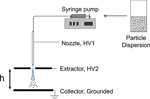
The electrospray setup is shown in . A syringe pump feeds a particle suspension to a metallic nozzle with an I.D. of 30 μm, O.D. of 115 μm, and a blunt tip. Underneath the metallic nozzle was a thin, flat, metallic sheet with a circular opening of 3 mm positioned 1 mm away from the nozzle whose purpose was to “extract” the charged droplets from the liquid meniscus region. Downstream of the extractor was a grounded plate at a distance h from it, on which the particles were deposited. There are two relevant electric fields at play for this setup: the one established by the voltage difference between nozzle and extractor (HV1 – HV2), providing the onset electric field for the cone-jet mode, and the electric field difference between the extractor and collector (HV2 – Ground) providing the field driving the droplets to their end location. The use of an extractor is optional but highly beneficial, as it decouples the two electric fields, providing an extra degree of freedom to control the trajectories of the droplets, the droplet evaporation time, and the particle impact velocity, as discussed in the next section.
We used two sources of commercially available nanoparticles: a TiO2 dispersion with 15 nm anatase particles in 2-propanol (US-Nano, US7830), and a TiO2 powder with 80% 20 nm anatase particles and 20% 80 nm rutile particles (Evonik-Degussa, P-25). provides details on the electrospray solutions used with these particles. Particle suspensions were observed visually for several days revealing no visible signs of sedimentation and subjected to sonication just prior to conducting electrospray experiments.
Table 1. Electrospray solution composition, conductivity (range), flow rates, and current (range).
Hydrochloric and nitric acid were used to enhance the electrical conductivity of the TiO2 solutions and electrostatically stabilize the dispersions (Modesto-Lopez and Biswas Citation2010). Dimethyl sulfoxide (DMSO) was used in the P-25 TiO2 solutions to slow down droplet evaporation.
Mobility analysis to determine the particle charge was carried out on an electrospray with a ZnO nanoparticle dispersion (Sigma, 721085) using a planar Differential Mobility Analyzer (DMA) from SEADM (Rus et al. Citation2010), as detailed in the online supplementary information (SI).
Scanning electron microscopy was performed using a Hitachi SU-70. The resulting images were processed using the ImageJ software to measure the diameters of the nanoparticles. For the 15 nm anatase TiO2 particles, nitrogen physisorption (Quantrachrome Autosorb-3B) and multipoint BET (Brunauer, Emmett, Teller) were used to assess the specific surface area. For these measurements, particles were washed and vacuum dried and the resulting coarse powder was ground and calcinated at 600°C for 24 h to remove any organic residue. Additional details on sample preparation for electron microscopy can be found in the SI.
provides further details on experimental conditions to be discussed in the following section. The parameters that were adjusted include: Peclet number, size of nanoparticles and aggregates (relevant to ), volatility of the electrospray liquid relevant to ), electrode separation, electric field strength, deposition time, deposit diameter, and thickness. E2 and h2 are values for a secondary electric field relying on a second extractor not shown in that was used to focus the electrospray deposit area in some experiments (to speed up film growth). Estimations for Peclet number in these experiments used the values of the secondary field experienced by the particles upon deposition.
Table 2. Experimental details (see text) for nanoparticle deposits in ensuing figures.
3. Criteria for control of aerosol deposition
Generating an aerosol and directing it toward a substrate for deposition lends itself to a high degree of control through multiple degrees of freedom. In principle, there are several means to control the structure of the deposit, including factors that can be affected in the aerosol phase and others associated with post-deposition deposit restructuring, such as annealing. Here, we focus only on the first type.
We shall cast the discussion in terms of characteristic times of the process, including: a deterministic time associated with the net force driving the aerosol toward the deposit, a diffusion time associated with the thermal motion of the particle, an evaporation time associated with the evaporation of the liquid in the suspension from which the cloud of solid particles forms and the residence time between the aerosol source and the deposit. There are also two characteristic length scales in the process: the particle size, which results from the initial particle size and/or particle loading of the dispersed droplets, and the distance between aerosol source and the substrate that is orders of magnitude larger than the particle size. Using the aerodynamic diameter d as a characteristic length (equal to the particle diameter, dp, when depositing single particles and the aggregate diameter, da, when depositing multiple particles per droplet), we can define a convective lifetime,[1] where the deterministic velocity
is, in turn, defined as
[2]
This expression results from the balance of the electric force experienced by the particle because of its residual net electric charge and its drag. The electric field is simply defined as that of a parallel plate capacitor and is equal to the potential difference between the extractor and collector, , over their distance from each other,
, neglecting any field penetration from the cone-jet region of the electrospray and any local intensification of the electric field due to “roughness” of the deposit. The rest of the symbols in EquationEquation (2
[2] ) are:
, the charge on the particle, µ, the dynamic viscosity of air, and
, the Stokes–Cunningham correction factor accounting for non-continuum effects (Cunningham Citation1910). The expression of EquationEquation (2
[2] ) presupposed that the particle experiences only electric force and viscous drag, which is the case for electrospray-generated aerosols. Other situations may be more complex if multiple phoretic effects are at play.
The diffusion time associated with the particle Brownian motion is[3] where
is the particle Stokes–Einstein diffusion coefficient,
is Boltzmann's constant, and T is its temperature (Mädler and Friedlander Citation2007). The ratio of these two times leads to a particle Peclet number defined as
[4]
The high Pe limit defines ballistic deposition, which turns into a more and more diffusional type of deposition as Pe decreases. Microscopic evidence for , and experimental values for
and
lead to a straightforward determination of
once the charge on the particle is established through an independent and more detailed measurement of the charge distribution. The Peclet number can be interpreted also as a ratio of forces (phoretic over thermal) or speed (deterministic over stochastic).
Another factor under control is the size of the depositing particle since the concentration of nanoparticles suspended in each electrospray droplet controls whether or not the particles deposit individually as in dilute suspensions, or if they aggregate during the droplet flight to the substrate prior to deposition. The concentration of particles in each droplet can be related to the concentration of particles in the electrospray solution because the diameters of the droplet from the electrospray are well described by the following scaling law (de la Mora and Loscertales Citation1994):[5] where Q is the flow rate, ϵ is the dielectric constant, and σ is the electrical conductivity of the liquid. G[ϵ] is a semi-empirical function of the dielectric constant of the liquid, which typically has values of the order unity (Chen and Pui Citation1997). We can now express the concentration, [C] (wt.%) of the nanoparticle dispersion to obtain, on average, N nanoparticles per electrospray droplet as
[6] where dp and ρp are the nanoparticle diameter and density, respectively. When multiple particles are present in each electrospray droplet, spherical aggregates are formed as the liquid evaporates. The aggregate diameters are estimated from
[7] where A is experimentally of unity order, da is the aggregate diameter, dp is the primary particle diameter, N is the number of primary particles per aggregate, and Df is 3 for spherical aggregates (Friedlander Citation2000). The option of depositing either single nanoparticles or aggregates of a particular size is a powerful tool for controlling film density and morphology, as shown below. It affects two of the above listed characteristic times: tconv∼ d2, tdiff ∼ d3, and their ratio, Pe ∼ d, where d is to be interpreted as the size of the single nanoparticle, dp, in the first case and the effective diameter of the aggregate, da, in the other.
Since the particles constituting the deposit are initially suspended in a liquid, the evaporation rate of the liquid carrier from the dispersed droplet would affect the nature of the deposit. In one limit the particle or aggregate would deposit dry, in another it would deposit partially wet, with residual evaporation at the substrate. These two limit-behaviors may affect the performance of the deposit drastically through changes in its connectivity, which is another parameter we can control. Also in this case we can define two characteristic times, a droplet evaporation time, as, based on the steady state evaporation of a droplet (d-square law) corrected for convective effects (Rosner Citation1986), where
is the droplet diameter (distinct from
) and K is the evaporation coefficient; and the mean residence time,
between extractor plate and substrate, under the assumption that the droplets reach terminal conditions quickly. The residence time must be larger than the evaporation time to ensure complete evaporation of the droplet before it reaches the substrate. These two times are compared in a dimensionless Damkhöler number for evaporation,
Therefore, the thin film will be made of initially completely dry particles in the limit of
In the opposite extreme when Daevap ≪ 1, the droplet lifetime is much longer than the residence time. In this undesirable scenario, liquid accumulates at the substrate and coffee-ring patterns occur after drying—a result no different than simply drop-casting the solution onto a substrate. For Daevap ∼ 1, when the droplet evaporation time is of the same order as the residence time, liquid accumulation at the substrate is avoided, but the particle(s) may not be fully dry upon deposition. Even in this case of partially wet impacting particles, the film morphology is not the same and its performance may be severely affected.
Of the two dimensionless numbers, Pe and Daevap ∼ 1, the first will be quantified through a determination/estimation of particle size, charge, and electric field, the second will be used only qualitatively, as part of the discussed conceptual framework to characterize deposition features: its quantitative determination is complicated by the multicomponent composition of some of the solutions that affects the droplet evaporation time and can be quantified only through computational modeling that is outside the scope of this work.
4. Results and discussion
4.1. Size, charge, and Peclet number of individual nanoparticles
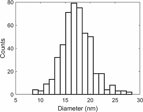
The particle size distribution of the 15 nm anatase TiO2 dispersion was characterized by drop casting a very dilute dispersion on a silicon wafer for subsequent SEM analysis. Roughly 450 particles were counted using ImageJ software and the particle size distribution is shown in . Using nitrogen physisorption and a multipoint BET plot for the powder, we measured a specific surface area of the powder at 82.51 m2/g. The pore size distribution showed that no micropores (pores <2 nm) were present, which implies that the particles were solid. With this assumption, a particle diameter of 17.2 nm was estimated, in agreement with the SEM results. Both of these values are slightly larger than the 15 nm specification from the provider. One explanation is that the SEM resolution is at its limit near the tail of the distribution. Blurry or fuzzy edges in combination with the burning of nanoparticles from the imaging electrons could lead to slightly overestimated measurements. For the BET results, the calcination step at 600°C might have caused some sintering of the nanoparticles, slightly reducing their specific surface area.
Figure 2. Particle size distribution for USNano anatase particles. The average diameter in this distribution corresponds to 17.3 nm with a standard deviation of 3 nm.
Before the Peclet number can be estimated from EquationEquation (4[4] ), a value for the charge must be assigned for the nanoparticles. Ancillary mobility measurements on electrosprayed ZnO nanoparticles allowing for full droplet evaporation showed that the residual charge equals the Rayleigh limit charge (Rayleigh Citation1882) of a liquid droplet with a diameter equivalent to that of the particle. In other words, the ZnO nanoparticle retained essentially all of the charge from the liquid droplet just before it fully evaporates with a full transfer from the liquid to the surface of the nanoparticles. This charge is not to be confused with the initial charge on the liquid droplet at the electrospray source because of the multiple fissile processes occurring before the droplet had shrunk to roughly the size of the residual nanoparticle (Gomez and Tang Citation1994). During each fission both charge and, to a lesser extent, liquid mass are ejected, which would severely affect the residual charge once most of the liquid has evaporated.
While the charge measurement was conducted on ZnO nanoparticles because of restrictions in access to the necessary instrumentation, we can assume that the charging level would be similar for electrosprays with TiO2 nanoparticles because of the similar size range, chemical makeup, and other observations in the literature (see the SI). The rationale is that metal oxide nanoparticles have many oxygen groups on the surface that have high affinity for ions, which allows the particles to retain essentially all of the charge that is available just as the liquid evaporates.
Distributions in both size and charge will result in variation in the estimation of the Peclet number, as described in EquationEquation (4[4] ). From the size variation of roughly ±17% of the TiO2 particles and the charge distribution of ±12% (see the SI), we would expect an uncertainty of ±20% in the Peclet number.
4.2. Deposits of individual nanoparticles
We deposited a series of films with increasing Pe by increasing the driving electric field, as shown in . The series of film cross-sections with the TiO2 nanoparticles clearly show an evolution from a more diffusional type of deposition, where the film is mostly comprised of randomly oriented dendritic structures, to a ballistic deposition, where the film becomes much better ordered with tree-like structures aligning vertically with the electric field. An example of the top-down view observed in our 15 nm anatase nanoparticle TiO2 deposits is shown in .
Figure 3. SEM cross-sectional images of 15 nm anatase TiO2 films showing the transition from less diffusional to more ballistic deposits with increasing Pe. The horizontal bar roughly denotes the top of each film.
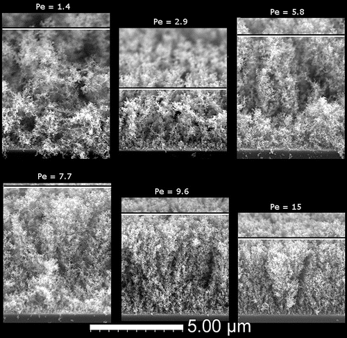
Figure 4. Top view of a typical deposit depicting nanoparticle island formation. Particles are 15 nm anatase TiO2 deposited with Pe = 7.7.
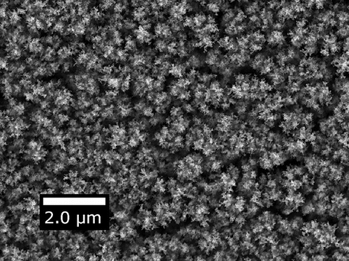
The Brownian dynamics simulation in Kulkarni and Biswas (Citation2004) that predicts film structure for charged particles deposited in an electric field showed two unique morphologies: a dendritic one and a more compact one formed by a small electric field and large electric field, respectively. Estimating Pe for the two simulated deposits yields Pe < 1 for the dendritic deposit and Pe > 1 for the more compact one. A similar estimate can be made in terms of their speed ratio, the ratio of deterministic velocity over thermal one, yielding values that are 28% larger than Pe because of uncertainties associated with the particle density entering the thermal speed. The density would be an additional unknown since it differs at the nanoscale from the value of the bulk. Another set of computational studies uses a Peclet-based definition (Castillo et al. Citation2010, Citation2014) and shows the emergence of the same two types of morphologies. In fact, top-down images of simulated deposits in (Castillo et al. Citation2014) match very closely the images of our experimental deposits as in . Some experimental evidence was presented in support of the simulated deposits, but the connection was not pursued quantitatively. The chosen operating conditions of the electrospray led to multiple nanoparticles residing in each droplet and probably incomplete droplet evaporation, neither of which was accounted for in the model (Castillo et al. Citation2014). In contrast, the present electrospray experiments were crafted under well-defined conditions by depositing single nanoparticles thereby avoiding particle aggregation, minimizing the droplet volume and using volatile solvents to ensure dry deposition.
A flame study synthesizing particles and depositing them thermophoretically (Zhang et al. Citation2012) also provided evidence of the formation of diffusional deposits when the thermophoretic velocity was smaller than the thermal velocity. Another investigation on the synthesis of TiO2 and SiO2 nanoparticles from a plasma reactor showed densification of nanoparticle films with the application of a bias voltage, i.e., increasing the deterministic velocity of the particles (Kubo et al. Citation2013). Our result confirms experimentally the theoretical and computational description of the interplay between the thermal velocity associated with Brownian motion and the deterministic, terminal velocity originating from the charge on the particle in an electric field over a wide range of impact velocities.
4.3. Deposits of nanoparticle aggregates
When the nanoparticle concentration is increased in the electrospray solution, multiple nanoparticles are captured within each droplet at the breakup of the liquid meniscus. After full droplet evaporation, the particles compact into a spherically shaped aggregate with diameters that agree with EquationEquation (7[7] ), as also observed in other studies (Modesto-Lopez and Biswas Citation2010). shows SEM images of a prototypical electrospray deposit of P-25 TiO2 nanoparticle aggregates with top view (left) and cross-sectional view (right).
Figure 5. SEM images of a P-25 TiO2 nanoparticle aggregate film from a top view (left) and cross-section (right). The arrows in the right image indicate the position of crevices. The estimated Peclet number for this deposit was 3.6 × 10².
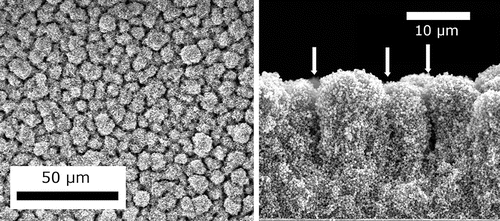
In this specific case, an average of 2700 particles were loaded in each droplet by adjusting both the particle loading in the slurry to 16 mg/mL and the droplet size. The top view exhibits a pattern with “islands” of characteristic dimension of approximately 7 um, separated by deep crevices, as evidenced by the cross-sectional view on the right. The deposit appears reasonably dense as compared to those obtained with much lighter particle loading per droplet. Deposits with different aggregate sizes can easily be formed by simply adjusting droplet size (via liquid conductivity or flow rate) and/or the nanoparticle concentration.
shows the film structure for a series of films deposited with constant total mass loading and film area but different agglomerate size. The lower the droplet concentration and aggregate size, the less porous the film, as suggested by its reduced thickness. The nonlinear dependence of deposit thickness on particle concentration suggests that the deposit microstructure changes with the droplet nanoparticle loading. Note that electrospray deposition of aggregates occurs nearly exclusively in a ballistic manner: the large aggregate sizes result in a vastly reduced thermal velocity and a much larger charge on the aggregate in comparison to depositing single nanoparticles. As a result, aggregate deposition typically corresponds to Pe ≫ 1. In the present case, the Peclet number ranged from 1.7 × 10², for the smallest agglomerate to 5.2 × 10² for the larger ones.
Figure 6. SEM cross-sections of films deposited with various P-25 TiO2 nanoparticle loadings and aggregate sizes. Nanoparticle concentrations are listed at the bottom and calculated aggregate diameters are listed at the top. The associated Peclet numbers (from left to right) are: 5.2 × 10², 4.5 × 10², 3.6 × 10², 2.9 × 10², and 1.7 × 10², respectively.

When depositing these films, we also investigated the film growth and its degree of uniformity. We examined SEM images of cross-sections for films grown for different periods of time to track film thickness as a function of deposition time and observed linear growth, as shown in .
Figure 7. Film thickness as a function of deposition time. Different curves represent different suspension concentrations (nanoparticle loading per droplet).
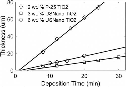
Trend lines increase in slope with suspension concentration and agglomerate size, but also depend on the overall film area, which is a function of emitted electrospray current, magnitude of external electric field, and distance between extractor and substrate. The trend lines for 3 wt. % and 6 wt. % US Nano TiO2 correspond to roughly equivalent film areas. The steeper slope associated with the 6 wt. % case is a result of the faster rate of deposition due to the increase of particle throughput. The 2 wt. % P-25 TiO2 trendline corresponds to a different film area and larger particles, so the slope cannot be directly compared to the other trendlines. However, in all three cases the linear relationship suggests that the film porosity and structure is invariant with overall film thickness with the exception of the first layers. The fact that the fit does not cross the origin, but rather has a negative y-intercept implies that the first layers of the film grow more slowly than the rest. This result was also found in simulated deposits (Castillo et al. Citation2014), in which the region near the solid substrate showed a higher density.
Low magnification SEM images, with one example presented in , shows that the electrospray deposited films are highly uniform in thickness over macroscopic areas. The edges of the deposit appear to taper off in thickness rather quickly. For example, for a ∼15 μm thick film, the edge tapers off approximately linearly within 50 μm. This relatively short distance means that non-uniformities around the perimeter of the deposit should not play a large role for circular deposits that are several millimeters in diameter.
4.4. Deposition of partially wet aggregates
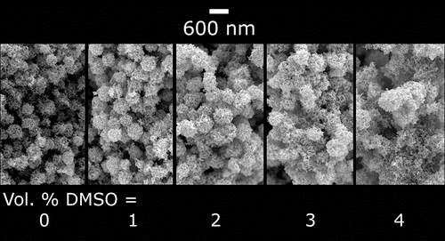
The morphology of electrospray deposited films can be further tuned by allowing the droplet evaporation lifetimes to approach the flight time toward the deposition substrate. This goal can be achieved in many ways. In the present case, we added small amounts of dimethyl sulfoxide (DMSO), a less volatile solvent, to the nanoparticle suspensions. As more DMSO was added to a P-25 suspension in ethanol and water, the film structure changed from a stack of spherical aggregates to a more interconnected web of particles. In this example, the agglomerate size was 430 nm, which corresponds to Pe = 3.6 × 10². The deposits in had nearly identical macroscopic features (deposit area and thickness) and were deposited with the same nanoparticle concentration, flow rate, and electrostatic conditions. The small addition of DMSO affected only the local film structure. The subtle change of the mesoporous film structure shown in can have drastic consequences on the film performance by affecting the connectivity of the deposit: for example, application of these films for dye sensitized solar cells showed that short circuit current density increased by 80% as a result of this tuning of the agglomerate wetness (Tang and Gomez Citation2015).
Figure 9. Evolution of webbed microstructure for deposition with partially wet nanoparticle with increased addition of dimethyl sulfoxide (DMSO). Images are from cross-sections of P-25 TiO2 films.
In another study with TiO2 suspended in ethylene glycol, the substrate was heated so the evaporation of the solvent occurred on the hot substrate, as opposed to during the transport toward the substrate (Zhu et al. Citation2014). Similar morphologies were found in studies dealing with synthesis by electrospraying liquid precursors onto a hot substrate (Kaelin et al. Citation2004; Perednis et al. Citation2005; Ghimbeu et al. Citation2009), though the mechanism is likely more complex because of the simultaneous deposition and chemical reaction taking place at the surface.
5. Conclusions
Using the electrospray we investigated nanoparticle deposition and the subsequent mesoporous film formation. The interplay between the nanoparticle deterministic velocity and the thermal velocity because of Brownian motion determines whether or not the deposits are diffusional in nature or ballistic. The deterministic velocity is due to the external electric field driving the deposition of the nanoparticles charged on average at the Rayleigh limit. We relied on three means to manipulate the structure and morphology of nanoparticulate films: impact velocity, particle concentration in the dispersed droplet, and solvent volatility. Results, interpreted in terms of a particle Peclet number and an evaporation Damkhöler number, provide a valuable guide for designing specific film structures to be tailored to the application. Principal conclusions are listed below:
Ballistic deposition results in compact, columnar structures that are aligned with the direction of the deterministic velocity of the particles, while diffusional deposition results in loosely connected, highly fractal, dendritic structures that are randomly oriented and highly porous.
The observed film structures for both ballistic and diffusional deposition match closely to films predicted by Monte Carlo simulations, which, until now, had limited experimental verification.
Films formed by the electrospray are highly uniform over a large area and the film structure is invariant with thickness, suggesting that growth occurs uniformly with thickness.
Reducing the liquid volatility can be used to increase the connectivity of the deposit by allowing nanoparticles to deposit partially “wet.” The resulting structure is morphologically unique and performs differently from deposits obtained when the droplets evaporate fully before deposition.
The method can be use not only to deposit spherical nanoparticles individually, but also aggregates, by electrospraying solutions with controlled nanoparticle loads and retaining in both cases size control.
UAST_1303573_Supplementary_file.zip
Download Zip (200 KB)Acknowledgments
The authors thank Dr. Michael Rooks for his assistance with scanning electron microscopy; Professor Juan de la Mora for his assistance with the differential mobility analyzer; and the use of facilities supported by the Yale Institute for Nanoscience and Quantum Engineering (YINQE) and NSF MRSEC DMR 1119826.
Funding
The authors gratefully acknowledge the financial support of the National Science Foundation (Grant CMMI-1335383, Dr. Khershed Cooper, Program Manager).
References
- Bochenkov, V. E., and Sergeev, G. B. (2010). Sensitivity, Selectivity, and Stability of Gas-Sensitive Metal-Oxide Nanostructures, in Metal Oxide Nanostructures and Their Applications, A. Umar and Y. B. Hahn, eds, American Scientific Publishers, Los Angeles, CA, pp. 31–52.
- Castillo, J. L., Martin, S., Rodriguez-Perez, D., Perea, A., and Garcia-Ybarra, P. L. (2014). Morphology and Nanostructure of Granular Materials Built from Nanoparticles. KONA Powder Part. J., 31:214–233.
- Castillo, J. L., Rodriguez-Perez, D., Martin, S., Perea, A., and Garcia-Ybarra, P. L. (2010). Structure of Granular Deposits Formed by Aerosol Particles Conveyed by Fluid Streams, in Progress in Industrial Mathematics at ECMI 2008. Mathematics in Industry, A. D. Fitt et al., eds., Springer, Berlin Heidelberg, pp. 455–461.
- Chan, B. P., and Leong, K. W. (2008). Scaffolding in Tissue Engineering: General Approaches and Tissue-Specific Considerations. Eur. Spine J., 17:S467–S479.
- Chen, D., and Pui, D. Y. H. (1997). Experimental Investigation of Scaling Laws for Electrospraying: Dielectric Constant Effect. Aerosol Sci. Technol., 27:367–380.
- Cloupeau, M., and Prunet-Foch, B. (1989). Electrostatic Spraying of Liquids in Cone-Jet Mode. J. Electrostat., 22:135–159.
- Cunningham, E. (1910). On the Velocity of Steady Fall of Spherical Particles through Fluid Medium. Proc. R. Soc. Lond. A: Math. Phys. Eng. Sci., 83(563):357–365.
- de la Mora, J. F., and Loscertales, I. G. (1994). The Current Emitted by Highly Conducting Taylor Cones. J. Fluid Mech., 260:155–184.
- Friedlander, S. K. (2000). Smoke, Dust, and Haze: Fundamentals of Aerosol Dynamics, Oxford University Press, New York.
- Ghimbeu, C. M., Lumbreras, M., Schoonman, J., and Siadat, M. (2009). Electrosprayed Metal Oxide Semiconductor Films for Sensitive and Selective Detection of Hydrogen Sulfide. Sensors (Basel, Switzerland), 9(11):9122–9132.
- Gomez, A., and Tang, K. (1994). Charge and Fission of Droplets in Electrostatic Sprays. Phys. Fluids, 6:404–414.
- Gomez, A., and Tang, K. (1996). Monodisperse Electrosprays of Low Electric Conductivity Liquids in the Cone-Jet Mode. J. Colloid Interf. Sci., 184:500–511.
- Green, M. A., Ho-baillie, A., and Snaith, H. J. (2014). The Emergence of Perovskite Solar Cells. Nature Photon., 8:506–514.
- Hogan, C. J., and Biswas, P. (2008). Porous Film Deposition by Electrohydrodynamic Atomization of Nanoparticle Sols. Aerosol Sci. Technol., 42(1):75–85.
- Jaworek, A. (2007). Electrospray Droplet Sources for Thin Film Deposition. J. Mater. Sci., 42:266–297.
- Jaworek, A., and Sobczyk, A. T. (2008). Electrospraying Route to Nanotechnology: An Overview. J. Electrostat., 66:197–219.
- Kaelin, M., Zogg, H., Tiwari, A. N., Wilhelm, O., Pratsinis, S. E., Meyer, T., and Meyer, A. (2004). Electrosprayed and Selenized Cu/In Metal Particle Films. Thin Solid Films, 457:391–396.
- Kojima, A., Teshima, K., Shirai, Y., and Miyasaka, T. (2009). Organometal Halide Perovskites as Visible-Light Sensitizers for Photovoltaic. J. Am. Chem. Soc., 131:6050–6051.
- Kubo, M., Ishihara, Y., Mantani, Y., and Shimada, M. (2013). Evaluation of the Factors that Influence the Fabrication of Porous Thin Films by Deposition of Aerosol Nanoparticles. Chem. Eng. J., 232:221–227.
- Kulkarni, P., and Biswas, P. (2004). A Brownian Dynamics Simulation to Predict Morphology of Nanoparticle Deposits in the Presence of Interparticle Interactions. Aerosol Sci. Technol., 38(6):541–554.
- Li, X., Hao, X., Abudula, A., and Guan, G. (2016). Nanostructured Catalysts for Electrochemical Water Splitting: Current State and Prospects. J. Mater. Chem. A, 4:11973–12000.
- Lima, R. S., and Marple, B. R. (2007). Thermal Spray Coatings Engineered from Nanostructured Ceramic Agglomerated Powders for Structural, Thermal Barrier and Biomedical Applications: A Review. J. Thermal Spray Technol., 16:40–63.
- Mädler, L., and Friedlander, S. K. (2007). Transport of Nanoparticles in Gases: Overview and Recent Advances. Aerosol Air Qual. Res., 7(3):304–342.
- Modesto-Lopez, L. B., and Biswas, P. (2010). Role of the Effective Electrical Conductivity of Nanosuspensions in the Generation of TiO2 Agglomerates with Electrospray. J. Aerosol Sci., 41(8):790–804.
- O'Regan, B., and Gratzel, M. (1991). A Low-Cost, High-Efficiency Solar Cell based on Dye-Sensitized Colloidal TiO2 Films. Nature, 353:737–740.
- Perednis, D., Wilhelm, O., Pratsinis, S. E., and Gauckler, L. J. (2005). Morphology and Deposition of Thin Yttria-Stabilized Zirconia Films using Spray Pyrolysis. Thin Solid Films, 474:84–95.
- Prevo, B. G., Kuncicky, D. M., and Velev, O. D. (2007). Engineered Deposition of Coatings from Nano- and Micro-Particles: A Brief Review of Convective Assembly at High Volume Fraction. Colloids Surfaces A: Physicochem. Eng. Aspects, 311:2–10.
- Rayleigh, L. (1882). On the Equilibrium of Liquid Conducting Masses Charged with Electricity. Phil. Mag., 14(87):184–186.
- Rosner, D. E. (1986). Transport Processes in Chemically Reacting Flow Systems. Butterworth Publishers, Stoneham, MA.
- Rus, J., Moro, D., Sillero, J. A., Royuela, J., Casado, A., Estevez-Molinero, F., and Fernandez de la Mora, J. (2010). IMS–MS Studies based on Coupling a Differential Mobility Analyzer (DMA) to Commercial API–MS Systems. Int. J. Mass Spectrom., 298:30–40.
- Song, M.-K., Park, S., Alamgir, F. M., Cho, J., and Liu, M. (2011). Nanostructured Electrodes for Lithium-Ion and Lithium-Air Batteries: The Latest Developments, Challenges, and Perspectives. Mater. Sci. Eng. R Rep., 72(11):203–252.
- Tang, J., and Gomez, A. (2015). Control of the Mesoporous Structure of Dye-Sensitized Solar Cells with Electrospray Deposition. J. Mater. Chem. A, 3:7830–7839.
- Tassopoulos, M., O'Brien, J. A., and Rosner, D. (1989). Simulation of Microstructure/ Mechanism Relationships in Particle Deposition. AlChE J., 35(6):967–980.
- Taylor, S. G. (1964). Disintegration of Water Drops in an Electric Field. Proc. R. Soc. Lond. Ser. A, Math. Phys. Sci., 280:383–397.
- Wilhelm, O., Madler, L., and Pratsinis, S. E. (2003). Electrospray Evaporation and Deposition. J. Aerosol Sci., 34:815–836.
- Zhang, Y., Shuiqing, L., Deng, S., Yao, Q., and Tse, S. D. (2012). Direct Synthesis of Nanostructured TiO2 Films with Controlled Morphologies by Stagnation Swirl Flames. J. Aerosol Sci., 44:71–82.
- Zhu, T., Li, C., Yang, W., Zhao, X., Wang, X., Tang, C., Mi, B., Gao, Z., Huang, W., and Deng, W. (2014). Electrospray Dense Suspensions of TiO 2 Nanoparticles for Dye Sensitized Solar Cells. Aerosol Sci. Technol., 47(12):1302–1309.

