ABSTRACT
Pressurized metered dose inhalers (pMDI) produce large numbers of droplets with smaller sizes than 5 μm to treat asthma and other pulmonary diseases. The mechanism responsible for droplet generation from bulk propellant liquid is poorly understood, mainly because the small length scales and short time scales make it difficult to characterize transient spray formation events. This article describes the development and findings of a numerical atomization model to predict droplet size of pharmaceutical propellants from first principles. In this model, the velocity difference between propellant vapor and liquid phase inside spray orifice leads to formation of wave-like instabilities on the liquid surface. Two variants of the aerodynamic atomization model are presented based on assumed liquid precursor geometry: (1) cylindrical jet-shaped liquid ligaments surrounded by vapor annulus; (2) annular liquid film with vapor flow in the core. The growth of instabilities on the liquid precursor surfaces and the size of the subsequently formed droplets are predicted by numerical solutions of dispersion equations. The droplet size predictions were compared with phase doppler anemometry (PDA) data and the predictions were in good agreement with the number mean diameter D10, which is representative of the respirable droplets. The temporal behavior of droplet size production was captured consistently well during the period of the first 95% of the propellant mass emission. The outcome of our modeling activities also suggests that, in addition to saturated vapor pressure of the propellant, its viscosity and surface tension are also key properties that govern pMDI droplet size.
© 2017 American Association for Aerosol Research
EDITOR:
1. Introduction
Pressurized metered dose inhalers (pMDI) are well known for their ability to form aerosols with a large numbers of therapeutic droplets predominantly in the respirable size range 1–5 µm. The mechanism responsible for droplet generation from bulk formulation is known to be transient, turbulent, and highly complex (Finlay Citation2001).
Early experimental work by Polli et al. (Citation1969) identified key factors affecting the particle size of pMDI aerosols: propellant vapor pressure and spray orifice size, as well as drug particle size, drug concentration, and presence of surfactant in the suspension formulation. Fletcher (Citation1975) studied steady flows of flashing mixtures of CFC propellants 11, 12, and 114 through a twin-orifice system. A theoretical model of the propellant mass flow rate and aerosol velocity was developed. Measurements of the mass median diameter (MMD) of the aerosol particles for spray orifices with diameter of 0.25 and 0.58 mm yielded an empirical correlation relating the MMD to the spray orifice diameter.
Studies of this type are very important for the pharmaceutical industry and are routinely used in product development and quality assurance procedures (FDA Citation1998). However, impactors characterize the final particle size distribution, whereas the aerosol source produced by a pMDI will contain significant quantities of propellant liquid. More recent studies (Brambilla et al. Citation1999; Stein and Myrdal Citation2004; Ivey et al. Citation2014) have developed empirical correlations for the initial spray droplet size, i.e., the spray source produced at the actuator orifice. The models predict the initial droplet size at the spray orifice exit from the residual droplet size measured by cascade impactors assuming that (i) evaporation is the only mechanism responsible for reduction of the droplet size after emission from the pMDI and (ii) all volatile formulation components are fully evaporated at point of impaction.
Using an early version of these techniques, Clark (Citation1991) measured the droplet size of propellant aerosols with known amounts of dissolved surfactants with an aerodynamic particle sizer (APS). Assuming that the cause of atomization of liquid ligaments in the spray orifice was aerodynamic shear, Clark developed an empirical correlation for droplet size as a function of the peak pressure developed in the expansion chamber and the vapor quality
. He obtained the following expression for the mass median aerodynamic diameter MMAD (in µm) of a pMDI spray droplet source:
[1] where
.
Equation (Equation1[1] ) captured the trends relating to the effects of the volatility of the formulation on the MMAD of pMDI aerosols by setting constant
for continuous discharge and
for metered discharge.
Dunbar and Miller (Citation1997) compared Clark's expression with a range of droplet size correlations for industrial atomizers (Lefebvre Citation1989). The predictions were validated against phase Doppler anemometry (PDA) measurements of pMDI spray droplet size (Dunbar Citation1997). Equation (Equation1[1] ) was found to be the most accurate if used in conjunction with
as the constant for metered discharges. Wigley et al. (Citation2002) measured the droplet size of an HFA227 aerosol in the near-orifice region of a pMDI with PDA and found a reasonable match with droplet size predictions made using Equation (Equation1
[1] ) but with
.
In summary, Clark's atomization correlation is currently the best approach for the prediction of pMDI droplet size. However, different values of the constant are needed for continuous and metered sprays; different values are used by different groups modeling metered sprays. Recent work by Gavtash et al. (Citation2017) suggests that case-by-case adjustment may be required for different propellants. To the knowledge of the present authors, there are currently no approaches capable of predicting pMDI droplet size from first principles. This article develops Clark's aerodynamic atomization concept and applies numerical models to predict the instability of precursor liquid ligaments in the spray orifice to determine the size of the liquid fragments and droplets. The approach is integrated with the model of propellant two-phase flow inside a pMDI (Gavtash et al. Citation2017). Model predictions of droplet size are compared with four sets of PDA data by Myatt et al (Citation2015), Dunbar et al. (Citation1997), and Wigley et al. (Citation2002).
2. Conceptual model of primary atomization in pMDIs
Propellant expands from the metering chamber into the expansion chamber. A vapor–liquid mixture moves into the spray orifice, where the liquid precursor entities are formed that eventually produce droplets at the spray orifice. Fletcher (Citation1975) described the flow regime as the expanded propellant flow passes through the spray orifice of a pMDI: dispersed liquid ligaments surrounded by a continuous vapor flow. Clark (Citation1991) developed atomization model Equation (Equation1[1] ) based on this conceptual model. A mixture of liquid ligaments and propellant vapor enters the spray orifice; the propellant vapor provides the force to drive the flow through the spray orifice. The dominant atomization mechanism of the pMDI was assumed to be aerodynamic breakup similar to air-blast atomization. The ligaments experience high aerodynamic forces due to the faster-flowing vapor, which causes breakup of the ligaments into smaller fragments, which ultimately re-form into small spherical droplets. This work builds on Clark's aerodynamic atomization concept and combines it with numerical approaches to study instability and primary atomization of liquid ligaments in the spray orifice. The vapor and liquid phase will flow at different speeds. Aerodynamic forces between the vapor and liquid generate wave-like instabilities on the vapor–liquid interface. Amplification of these waves causes the liquid to break up and fine droplets are produced.
Details of the two-phase flow regime in the spray orifice of a pMDI are currently unknown. Fletcher (Citation1975) and Clark (Citation1991) assumed that the liquid phase is distributed in the spray orifice as ligaments surrounded by vapor. Versteeg et al. (Citation2006) reported flow visualizations in transparent models of a pMDI, which suggested the existence of an annular liquid film with a vapor core in the spray orifice during part of the spray event. This flow configuration has recently been described by Honnery et al. (Citation2016). Below, two variants of liquid atomization are developed on the basis of these two assumed liquid precursor flow regimes.
| • | cVariant 1: liquid jet precursor | ||||
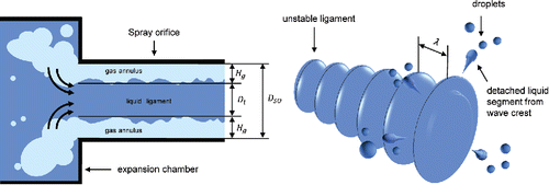
The first variant of the aerodynamic atomization model assumes that the liquid phase takes the shape of a liquid element traveling in the core of the spray orifice surrounded by an annulus of vapor. The shape of the ligament will be approximated by a cylinder (). Velocity differences between the vapor and liquid phase generate aerodynamic forces on the liquid cylinder, which causes wave-like disturbances on the vapor–liquid interface. These disturbances grow rapidly in amplitude and fragment the cylindrical liquid jet into aerosol drops ().
| • | Variant 2: liquid sheet precursor | ||||
Figure 1. Schematic of droplet generation from cylindrical liquid jet, using Reitz and Bracco (Citation1986) atomization model in pMDI.
The second variant of the aerodynamic atomization model assumes that the liquid forms a thin annular sheet along the walls of the spray orifice that surrounds a faster moving vapor flow in the core ().This liquid sheet experiences aerodynamic forces causing the growth of instabilities at the vapor–liquid interface.
Figure 2. Schematic of droplet generation from annular liquid sheet, using LISA mechanism (Senecal et al. Citation1999) in pMDI.
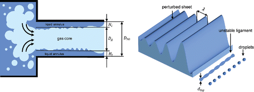
Amplification of unstable waves is responsible for sheet disintegration and formation of unstable cylindrical ligaments. These break up and contract into spherical droplets ().
2.1. Mathematical formulation
Next, two numerical models are developed of aerodynamic atomization of the precursor flows—cylindrical liquid ligaments and annular liquid films. The instability of these precursor entities is studied using Kelvin–Helmholtz (KH) model of the instability of cylindrical jets (Reitz and Bracco Citation1986) and the linear instability sheet atomization (LISA) model (Senecal et al. Citation1999), respectively. Aerodynamic atomization is strongly dependent on flow rate, velocity, and properties of fluid (Lefebvre Citation1989), so accurate prediction of these flow parameters is essential. In this study, the homogenous frozen model (HFM) is used for the prediction of flow rate and spray velocity, since it is the most successful two-phase flow model in pMDIs (Clark Citation1991; Wigley et al. Citation2002; Gavtash et al. Citation2014, Citation2017). All fluid properties are evaluated using REFPROP V.7.0. (National Institute of Standards and Technology, Gaithersburg, MD, USA).
2.1.1. Precursor liquid length scale and atomization velocity scale
Aerodynamic atomization models based on the conceptual models introduced earlier require as input the length scale of the precursor liquid entities: the diameter/radius of liquid jet (Variant 1) or thickness of the annular liquid film (Variant 2). These precursor length scales can be estimated if the void fraction of the vapor–liquid flow inside the spray orifice is known. Since the HFM is chosen for flow predictions, the void fraction of the homogenous vapor–liquid flow in the spray orifice is evaluated using the following expression (Whalley Citation1987):
[2]} where
is the vapor mass fraction (or quality) and
is the specific volume and subscripts
and
refer to the liquid and the vapor phase, respectively.
As shown in and , the void fraction is related to the precursor liquid length scale by the following expressions:[3a]
[3b] where
is the spray orifice cross-sectional area and
is the spray orifice diameter;
is the cross-sectional area occupied by the vapor;
and
are corresponding diameters occupied by the vapor phase and liquid phase, respectively.
The radius of the liquid jet in and the thickness
of the annular liquid film in can be found as follows:
[4]
[5]
Thus, the initial length scale of the liquid element in a spray orifice can now be estimated using Equations Equation(2)–(5) from the flow quality and the specific volumes of the liquid and the vapor phase,
and
, respectively. These quantities are all generated by the HFM internal flow model (see Gavtash et al. Citation2017 for further details).
The relative velocity between the liquid and vapor phase is taken to be equal to two-phase flow velocity. This is a common approximation made in phenomenological modeling of atomizers in cases where only one flow velocity scale is available (Lefebvre Citation1989; Razzaghi Citation1989; Schmidt et al. Citation1999; Senecal et al. Citation1999).
2.1.2. Variant 1: Breakup of liquid jet
The precursor liquid entities in the first aerodynamic atomization model are assumed to be cylindrical ligaments. The interaction between these ligaments and the surrounding vapor flow is assumed to be similar to the behavior of liquid jets. The disintegration of liquid jets is predicted using the jet stability analysis described in detail by Reitz and Bracco (Citation1986), also known as the Kelvin–Helmholtz (KH) model. The theory develops and solves a dispersion equation for the amplification of infinitesimal disturbances on the vapor–liquid interface. The growth rates of waves are evaluated as a function of their wavelength. The maximum growth rate, which represents the most unstable wave, is found for a given set of flow conditions. Reitz (Citation1987) developed the following curve fits of numerical solutions of the dispersion equation for the maximum growth rate, , and the corresponding wavelength,
:
[6]
[7] where the non-dimensional groups appearing on the right-hand side of Equations (Equation6
[6] ) and (Equation7
[7] ) are defined as follows:
[8a]
[8b]
[9]
[10] where
is the density,
is the surface tension,
is the viscosity, and
is the radius of the cylindrical liquid jet. As stated above, the relative velocity
between liquid and vapor phase will be taken to be equal to the velocity predicted by the HFM model.
The diameter of the droplets at the spray orifice exit is proportional to the wavelength of the most unstable wave:
[11] where
is a model constant set equal to 0.61 as recommended by Reitz (Citation1987).
2.1.3. Variant 2: Breakup of liquid sheet
In the second variant of the aerodynamic atomization model, an annular liquid film on the spray orifice walls is the precursor liquid entity from which respirable droplets are subsequently formed (). The radius of a typical pMDI spray orifice is = 150–200 μm. Preliminary estimates based on flow calculations and visualizations in transparent nozzles suggest that the liquid film thickness
is typically 15–20 μm. Taking the size of small disturbances on the liquid film to be initially of the order of tenth of the sheet thickness, say 2 μm, the ratio of the disturbance amplitude and spray orifice radius is much smaller than unity. The instability of the thin annular liquid sheet can be studied as a flat sheet to first approximation. The behavior of unstable annular sheets has been studied by Jeandel and Dumouchel (Citation1999). A posteriori justification of this assumption is provided in the online supplementary information (SI), Section S.2.2.
The theory of disintegration and breakup of flat liquid sheets involves a dispersion equation for the evolution of initially small disturbances. Early analyses by York et al. (Citation1953) and Dombrowski and Johns (Citation1963) formed the basis of the linear instability sheet analysis (LISA) model of Senecal et al. (Citation1999) used in this work.
Solutions to the dispersion equation recognize two wave-generation regimes (i) short waves that are dominated by viscous and surface tension effects and (ii) long waves, which are governed by inertial and surface tension effects. The regimes can be distinguished on the basis of the gas-phase cut-off Weber number using the liquid half sheet thickness of , as the characteristic length (Senecal et al. Citation1999):
[12]
| • | Short wave regime | ||||
If , then short waves are generated. In this case, Senecal et al. (Citation1999) give the following expression for growth rate:
[13] where
is the density ratio between the gas and liquid phase (i.e.,
),
is the kinematic viscosity of the liquid, and
( =
) is the wave number. Numerical maximization of Equation (Equation13
[13] ) with respect to wave number (
) yields the maximum growth rate,
as a function of wave number,
. The wave number corresponding to the maximum growth rate is denoted by
.
The diameter of the ligament at the point of disintegration is assumed to be linearly proportional to the reciprocal of wave number
[14] where
is ligament constant, which takes a value of 0.5 (Hutcheson et al. Citation2008; Ghose et al. Citation2014).
| • | Long wave regime | ||||
If , then long waves are generated. In this wave generation regime, viscosity has negligible effect on wave growth and Senecal et al. (Citation1999) use the results of the inviscid analysis of Squire (Citation1953) to determine the wave number
of the most unstable wave disturbances:
[15]
The diameter of ligaments formed from the unstable liquid sheet during long-wave breakup is obtained from a mass balance by assuming that two ligaments are formed per wavelength (Senecal et al. Citation1999):[16]
Regardless of the responsible wave regime for breakup, the diameter of the droplets can be obtained based on capillary instability analysis of the initial ligaments (Senecal et al. Citation1999):[17] where
denotes the ligament Ohnesorge number defined as follows:
[18]
2.1.4. Near-orifice droplet flashing
The aerodynamic atomization models will be validated by comparison of the predicted droplet size with Phase-Doppler anemometry (PDA) measurements. PDA data can only be acquired at around 15 mm from the spray orifice exit. The HFM internal flow model provides the two-phase properties including the temperature of the propellant at the spray orifice exit. This model suggests that the propellant droplet emerging from the spray orifice will be superheated. Before the droplets are measured, the superheated propellant will flash in the near-orifice region causing a reduction of the mass of newly formed liquid droplets. This loss of mass has to be accounted for, since it constitutes a further size reduction mechanism.
shows a schematic of the spray in the near-orifice region immediately downstream from the spray orifice exit.
Figure 3. Schematic of spray development in near-orifice region immediately downstream from spray orifice in choked conditions, illustrating propellant flashing and associated droplet size reduction.
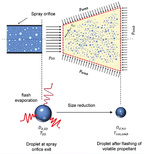
Evaporation of volatile formulation components will bring the droplets to thermodynamic equilibrium with its surroundings. Flash evaporation of droplets will occur very quickly, so it is reasonable to assume adiabatic conditions. Conservation of energy enables us to evaluate the change in near-orifice quality as a result of flashing:
[19]
In Equation (Equation19[19] ),
is the specific enthalpy of the propellant liquid and
is the latent heat. The subscript
denotes conditions immediately outside the spray orifice, subscript
denotes saturation state at ambient pressure and subscript
denotes conditions in the near-orifice region (at the exit of the analysis volume in ).
The final droplet mass in near-orifice region after flash evaporation can be obtained from the mass of droplets
emitted at spray orifice exit as follows:
[20] where
[21] with
is the droplet diameter,
is specific volume of liquid phase.
The size of the droplet after the flashing in near-orifice region is calculated as follows:[22]
This droplet size estimate will be compared with PDA data from the literature in the next section.
3. Results and discussion
The near-orifice droplet sizes predicted by variants 1 and 2 of the aerodynamic atomization model are compared with phase Doppler anemometry (PDA) data published in Myatt et al. (Citation2015a,Citationb), Dunbar et al. (Citation1997), and Wigley et al. (Citation2002). The relevant actuator/test parameters for the data are summarized in Tables S1–S3 in Section S1 of the SI. Before this comparison is made a priori checks are performed to ensure that the assumed aerodynamic atomization regimes in the theories of Reitz and Bracco (Citation1986) and Senecal et al. (Citation1999) are applicable. These checks can be made by post-processing results of the internal flow models and the outcomes are reported in the SI, Section S2.
3.1 Droplet size predictions
and compare the results of the predictions of near-orifice droplet sizes with D10 (arithmetic mean diameter) and D32 (Sauter mean diameter) as function of time from PDA measurements for HFA134a and HFA227 propellant system, respectively. D10 is representative of the large number of small, respirable droplets with size that is much smaller than 10 µm. The measured D32 values show large fluctuations, which are associated with the much smaller numbers of very large spray droplets (10–20 µm).
Figure 4. Prediction of spray droplet size compared with PDA measurements of Myatt et al. (Citation2015a,Citationb) (test case parameters in Table S1). (a) HFA134a; (b) HFA227.
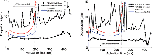
The temporal trends of the droplet size predicted by both breakup models reasonably follow the measured trend of D10. It can be seen that measured and predicted droplet size curves rapidly rise as two-phase propellant mixture with high vapor content starts to flow through the spray orifice. After a maximum is reached, the droplet size decreases gradually up to 100 ms for HFA134a and up to 150 ms for HFA227. This temporal behavior is associated with the filling and emptying of the expansion chamber as the spray event proceeds. The flow velocity experiences a corresponding reduction to a minimum point whereupon an almost linear increase of the velocity takes place (Dunbar et al. Citation1997; Wigley et al. Citation2002; Gavtash et al. Citation2017). This inverse relationship between droplet size and flow velocity is characteristic of aerodynamic atomization and was previously identified by Clark (Citation1991) and others (Dunbar et al. Citation1997; Gavtash et al. Citation2014; Myatt et al. Citation2015a,Citationb) in the context of pMDI spray events. Another important feature of and is the prediction of smaller droplet size for HFA134a propellant system compared with HFA227 propellant system, by both atomization model variants. This trend was previously observed in several studies such as Brambilla et al. (Citation1999), Stein and Myrdal (Citation2004), and Myrdal et al. (Citation2004), who measured the residual droplet size issued from a pMDI. The trend is attributable to higher saturated vapor pressure of HFA134a compared with HFA227, providing greater energy source for flow acceleration. Higher flow acceleration augments the growth rate of disturbances on precursor liquid and eventually leads to liquid fragmentation to smaller droplets. This is not readily apparent from PDA traces in and as D32 traces are largely unstable to be used for accurate size magnitude comparison. Furthermore, D10 values for both propellants are close in magnitude in the present data. This may be due to (i) errors associated with PDA equipment and/or (ii) different evaporation rates of HFA134a and HFA227 droplets.
Up to approximately 180 ms for HFA134a, and 230 ms for HFA227, the prediction curves lie within the region bounded by D10 and D32, suggesting that droplet size is predicted correctly. These time points correspond to emission of approximately 95% of the modeled metering chamber mass by the pMDI. The temporal size trend for the remaining portion of the propellant emission involves a large over-prediction of the droplet size. At this stage, the predicted velocity decays rapidly due to adiabatic cooling of the propellant in the HFM internal flow model. This causes the predicted droplet size to overshoot. In reality, heat transfer across the walls of the actuator can supply additional energy to the flow to maintain atomization during this phase of the spray event. This effect is currently not included in the internal flow model, so the predictions are poor for the final 5% of the emitted mass, so the trends are shown as dashed lines.
The timings of the peaks of predicted curves do not match exactly with the corresponding one for the measured D10. The discrepancy may be due to high rate of momentum transfer between the emerging plume and the surrounding ambient air, leading to slow-down of the plume. As a consequence, droplets arrive later at the point of PDA measurement. This phenomenon was previously noted to cause a small time shift between predicted flow velocity curve and PDA measurement curve (Gavtash et al. Citation2017). Evaporative size reduction due to heating by entrainment of surrounding air may also reduce the size of the measured droplets further. This discrepancy becomes more dominant if the measurement point is located further downstream.
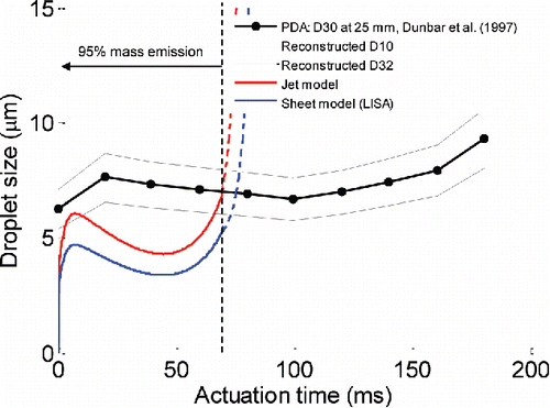
The results of the atomization model are compared against the PDA measurements of Dunbar et al. (Citation1997) for HFA134a, in . The modeling parameters of this test case are summarized in Table S2. The point of measurement is at 25 mm from the spray orifice and the time bin for PDA data averaging is 20 ms. As noted earlier, the large distance and long averaging time will cause smoothing of the variations in the measured droplet size. The original measurements in reported the volume mean diameter D30. Dunbar and Miller (Citation1997) suggested that the measurements reasonably follow a Rosin–Rammler curve with size parameter ranging from 8 to 12 µm and distribution parameter of
, although without supporting data. An attempt was made to reconstruct the corresponding D10 and D32 values using these parameters and the relations presented in Bailey et al. (Citation1983) for the Rosin–Rammler distribution. However, the ratio D32/D10 is much smaller than for the other datasets, which suggests that the distribution parameter is inaccurate, making the dataset only suitable for order-of-magnitude comparison. In spite of these reservations, shows that the temporal trend of the predicted droplet size is broadly in line with the PDA measurements. Important features of the trace such as initial peak and gradual size reduction are observable in both measurement and predictions.
Figure 5. Comparison of predicted spray droplet size against PDA measurements of Dunbar et al. (Citation1997).
shows model outcome comparison against measurement of Wigley et al. (Citation2002), for HFA227 propellant. The modeling parameters for this test case are summarized in Table S3. The data were acquired at 2.6 mm away from the spray orifice and are averaged over 5 ms time bins. The temporal profile is predicted very well, the magnitude of the droplet size is close to the measured D10 curve. The predictions of both jet and sheet breakup models falls between the measured D10 and D32, over the first 63 ms of the actuation, which represents 95% of the emitted propellant mass. The timing of the predicted droplet size peak is synchronized with the measured peak (less than 2 ms difference). It is likely that the good agreement with model predictions is due to the fact that the PDA measurement point is located very close to spray orifice. The droplets are also less affected by heat gain from the entrained air. Since the droplets arrive quickly at the measurement point, size reduction due to evaporation is not significant.
Figure 6. Comparison of predicted spray droplet size against PDA measurements of Wigley et al. (Citation2002).
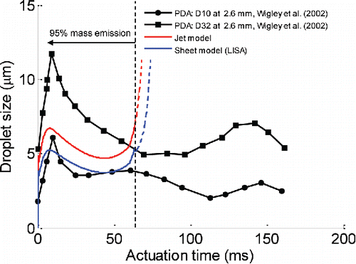
In the literature of industrial atomizers, outcomes of Equations (Equation11[11] ) and (Equation17
[17] ) are more commonly compared with D32 (Patterson and Reitz Citation1998; Senecal et al. Citation1999; Larmi and Tiainen Citation2003; Park et al. Citation2009), which is more widely used in spray applications. show that the droplet size predictions by the jet and sheet breakup models agree more closely with the measured D10 value. As emphasized earlier, both D10 and D32 metrics are important for pMDI sprays. The former is most representative of the large number of respirable droplets, whereas D32 captures information relating to the much smaller number of larger droplets, which are likely impact in the mouth and throat. In summary, the present comparison shows order-of-magnitude agreement between droplet size predictions and PDA data and the model predictions are more in line with D10, which represents the bulk of the therapeutically useful, smaller droplets produced by pMDIs emitted as part of 95% of the pMDI propellant mass.
3.2. Additional investigations
3.2.1. Breakup time
In the proposed primary atomization model, the breakup is assumed to occur within the spray orifice. In order for fragmentation of the liquid to be complete at the orifice exit, it is a necessary condition that the breakup time is smaller than the convection time. The results of a posteriori checks of these conditions are reported in the SI, Section S3. These confirm that the time required for sufficient growth of disturbance on precursor liquid inside the spray orifice is always less than the time required for the droplet to travel to the PDA measurement point.
3.2.2. Near-orifice droplet size reduction due to flashing
The ratio of the droplet size at the end of the near-orifice flashing region (Equation (Equation22
[22] )) and the droplet size
at the spray orifice exit (Equation (Equation11
[11] ) or (Equation17
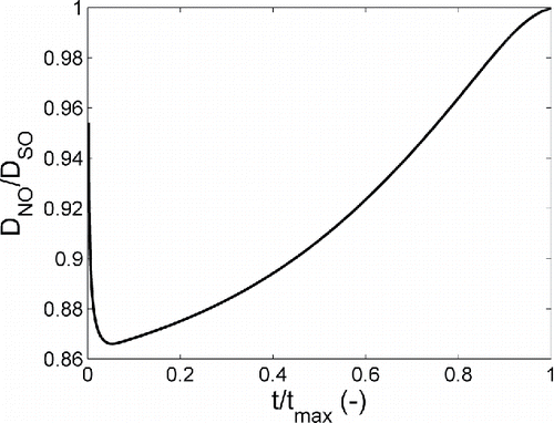
[17] )) is shown in for test case of Table S1. For the sake of simplicity of visualization, the horizontal time axis is normalized on its maximum value, to provide identical axes range. The result shows that near-orifice flashing is a significant secondary size reduction mechanism, which can initially reduce the predicted droplet diameter to 87% of its original size.
Figure 7. Ratios of near-orifice droplet size (after flashing) and spray orifice droplet size (before flashing) for modeling parameters of Myatt et al. (Citation2015a,Citationb), using HFA134a.
3.2.3. The effects of viscosity and phenomenological model constants on droplet size predictions
The influence of viscosity on model predictions is investigated by comparing the predicted wavelength of most unstable disturbance for viscous and inviscid cases for test case data given in Table S1. The breakup of inviscid jets and sheets was evaluated by setting the dynamic viscosity in Equation (Equation9
[9] ) and the kinematic viscosity
in Equation (Equation13
[13] ) equal to zero. For inviscid conditions, shows that the wavelength of the most unstable disturbance for the sheet model is predicted to be shorter than the jet model during the first approximately 160 ms. Inclusion of the effect of viscosity increases the wavelength of most unstable disturbances. This is a well-known effect as was pointed out previously (Reitz and Bracco Citation1986; Dumouchel Citation2008). shows that the most unstable wavelengths for liquid jets and sheets are predicted to be quite close when viscous effects are included.
Figure 8. Predictions of wavelength of most unstable disturbance and droplet size for inviscid/viscous sheet and jet models, corresponding to test case in Table S1 using HFA134a propellant (a) wave length (b) droplet size.
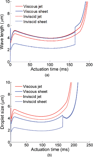
compares the temporal trends of the predicted droplet size after non-linear amplification of the most unstable wavelength for inviscid and viscous conditions. Even though the most unstable wavelength was almost identical for viscous jets and sheets, the predicted droplet size produced by the breakup of a viscous jet is now larger than the corresponding size for a viscous sheet. This difference is attributable to details of the phenomenological models that predict the non-linear reorganization of the products of unstable wave growth into spherical droplets. More specifically, the difference in predicted droplet size for jet breakup and sheet breakup are attributable to differences in the values of the phenomenological model constants in Equation (Equation11
[11] ) for jet breakup and
in Equation (Equation14
[12] ) for sheet breakup. Similar figures for the other modeling cases are presented in Section S4 of SI. The theory of unstable wave growth and droplet production used in the present work has been most widely applied to air-assist and air-blast atomization in the context of sprays of water and fuel. Typical droplet sizes (30–100 µm) for these sprays are an order-of-magnitude larger than pMDI aerosol droplets. Further work to confirm the applicability of aerodynamic atomization models will need to investigate the need for a one-off adjustment of these phenomenological constants for pMDI sprays.
4. Conclusion
In this work, Clark's aerodynamic atomization concept was expanded by developing two variants based on growing of infinitesimal disturbance leading to cylindrical jet breakup (Reitz and Bracco Citation1986; Reitz Citation1987) and annular sheet breakup (Senecal et al. Citation1999), respectively. This enabled the prediction of the droplet size emitted by a pMDI from first principles. It should be noted that the most unstable wavelength from linear stability analysis to predict the size of nonlinear structures resulting from an instability is quite approximate since it ignores nonlinear effects, e.g., due to large amplitude external disturbances and even bypass transition. Nevertheless comparison of model predictions with PDA measurements suggests that the model outcome is order of magnitude accurate.
Predictions of the atomization models were compared with mean diameter D10 and Sauter mean diameter D32 of pMDI sprays measured with PDA. The models correctly predicted the droplet size within the correct range between D10 and D32 in all but one case. Comparisons with available PDA data showed that model predictions are closest to the D10, which is representative of the large number respirable droplets, i.e., the therapeutically useful portion of the pMDI spray. Moreover, the temporal behavior of droplet size was consistently captured well during the initial period corresponding to emission of approximately 95% of the propellant mass. An inverse relationship between the droplet size and spray velocity was observed in the model outcomes. This agreed with previous experimental/theoretical studies (Clark Citation1991; Dunbar et al. Citation1997; Wigley et al. Citation2002; Myatt et al. (Citation2015a,Citationb) and suggests that the spray velocity is the major source of droplet fragmentation.
The bulk of the spray generation was predicted to take place in breakup regimes that are characterized by formation of fast-growing short waves on the surface of liquid segment resulting in the generation of small droplets with size that is much smaller than the initial liquid ligament or film. Differences between the droplet sizes predicted by the two models were found to be attributable to differences in the respective treatments of the final, non-linear liquid breakup for jet and sheet breakup. Both models agree reasonably well with PDA data, but neither is conclusively better. Rather than concluding on the basis of better agreement with PDA data that either of the assumed liquid precursor flow regimes in the spray orifice—cylindrical ligaments or annular film—is superior, it is recommended that this judgement be postponed until better information about the state of the flow in the spray orifice becomes available.
Comparison of the model results using inviscid and viscous assumptions suggests that the inclusion of viscosity leads to an increase in the predicted droplet size, particularly for the case of sheet model. This suggests that viscosity—probably in conjunction with surface tension—plays a significant part in determining the final droplet size. This was previously suggested by Smyth (Citation2003) and would imply that control of particle size may be possible by careful adjustment of the viscosity of the formulation. It is interesting to note that Brambilla et al. (Citation1999) have successfully managed to achieve such a result by adding specific amounts of ethanol to pharmaceutical propellants. Ethanol is an excipient, which is thought to reduce the vapor pressure, but will also modify the surface tension and viscosity of the formulation. The present theory only covers pure propellants. The effects of composition of the formulation on atomization of propellant-excipient mixtures clearly deserve future attention.
UAST_1327121_Supplementary_File.zip
Download Zip (539.6 KB)Funding
The authors gratefully acknowledge financial support for this research by Chiesi Farmaceutici SpA.
References
- Bailey, A. G., Balachandran, W., and Williams, T. J. (1983). The Rosin—Rammler Size Distribution for Liquid Droplet Ensembles. J. Aerosol Sci., 14(1):39–46.
- Brambilla, G., Ganderton, D., Garzia, R., Lewis, D., Meakin, B., and Ventura, P. (1999). Modulation of Aerosol Clouds Produced by Pressurised Inhalation Aerosols. Int. J. Pharm., 186(1):53–61.
- Clark, A. R. (1991). Metered Atomisation for Respiratory Drug Delivery. PhD Thesis. Loughborough University of Technology, Loughborough, UK.
- Dombrowski, N., and Hooper, P. C. (1962). The Effect of Ambient Density on Drop Formation in Sprays. Chem. Eng. Sci., 17(4):291–305.
- Dombrowski, N., and Johns, W. (1963). The Aerodynamic Instability and Disintegration of Viscous Liquid Sheets. Chem. Eng. Sci., 18(3):203–214.
- Dumouchel, C. (2008). On the Experimental Investigation on Primary Atomization of Liquid Streams. Exp. Fluids, 45(3):371–422.
- Dumouchel, C., and Ledoux, M. (1991). Atomization of Flat and Annular Liquid Sheets. Practical Use of Linear Theories, in Proceedings of ICLASS, 91, Gaithersburg, MD, USA, pp. 157–164.
- Dunbar, C. A. (1997). Atomization Mechanisms of the Pressurized Metered Dose Inhaler. Part. Sci. Technol., 15(3–4):253–271.
- Dunbar, C. A., and Miller, J. F. (1997). Theoretical Investigation of the Spray from a Pressurized Metered-Dose Inhaler. Atom. Sprays, 7(4):417–436.
- Dunbar, C. A., Watkins, A. P., and Miller, J. F. (1997). An Experimental Investigation of the Spray Issued from a pMDI Using Laser Diagnostic Techniques. J. Aerosol Med., 10(4):351–368.
- FDA Draft Guidance. (1998). Guidance for Industry (Draft). Metered Dose Inhaler (MDI) and Dry Powder Inhaler (DPI) Drug Products: Chemistry, Manufacturing, and Controls Documentation. US Food and Drug Administration, Center for Drug Evaluation and Research.
- Finlay, W. H. (2001). The Mechanics of Inhaled Pharmaceutical Aerosols: An Introduction. 6th ed. Academic Press, London.
- Fletcher, G. E. (1975). Factors Affecting the Atomisation of Saturated Liquids. PhD Thesis, Loughborough University of Technology, Loughborough, UK.
- Gavtash, B., Versteeg, H. K., Hargrave, G. K., Lewis, D., Church, T., and Brambilla, G. (2014). Linear Instability Sheet Atomisation (LISA) Model to Predict Droplet Size Issued from a pMDI, in Proceedings Of The ILASS – Europe 2014, 26th Annual Conference on Liquid Atomization and Spray Systems, Bremen, September, pp. 283–285.
- Gavtash, B., Versteeg, H. K., Hargrave, G., Myatt, B., Lewis, D., Church, T., and Brambilla, G. (2017). Transient Flashing Propellant Flow Models to Predict Internal Flow Characteristics, Spray Velocity, and Aerosol Droplet Size of a pMDI. Aerosol Sci. Technol., 51(5):564–575.
- Ghose, P., Patra, J., Datta, A., and Mukhopadhyay, A. (2014). Effect of Air Flow Distribution on Soot Formation and Radiative Heat Transfer in a Model Liquid Fuel Spray Combustor Firing Kerosene. Int. J. Heat Mass Transf., 74:143–155.
- Honnery, D., Mason-Smith, N., Duke, D. J., Kastengren, A. L., Chen, Y., Young, P., Traini, D., Lewis, D., and Edgington-Mitchell, D. (2016). New Insights into pMDI Operation using Synchrotron X-Ray Techniques, in Proceedings of Respiratory Drug Delivery Asia (RDD Asia), Goa, India, November 8–11, pp. 209–218.
- Hsiang, L. P., and Faeth, G. M. (1995). Drop Deformation and Breakup due to Shock Wave and Steady Disturbances. Int. J. Multiphase Flow, 21(4):545–560.
- Hutcheson, P. S., Chew, J. W., Thorpe, R. B., and Young, C. (2008). Assessment of Models for Liquid Jet Breakup, in ASME Turbo Expo 2008: Power for Land, Sea, and Air. American Society of Mechanical Engineers, pp. 1517–1529.
- Ivey, J. W., Lewis, D., Church, T., Finlay, W. H., and Vehring, R. (2014). A Correlation Equation for the Mass Median Aerodynamic Diameter of the Aerosol Emitted by Solution Metered Dose Inhalers. Int. J. Pharm., 465(1):18–24.
- Jeandel, X., and Dumouchel, C. (1999). Influence of the Viscosity on the Linear Stability of an Annular Liquid Sheet. Int. J. Heat Fluid Flow, 20(5):499–506.
- Ju, D., Shrimpton, J., and Hearn, A. (2010). The Effect of Reduction of Propellant Mass Fraction on the Injection Profile of Metered Dose Inhalers. Int. J. Pharm., 391(1):221–229.
- Larmi, M., and Tiainen, J. (2003). Diesel Spray Simulation and KH-RT Wave Model. SAE Technical Paper 2003-01-3231.
- Lefebvre, A. (1989). Atomization and Sprays. CRC Press, Boca Raton, FL.
- Liu, A. B., Mather, D., and Reitz, R. D. (1993). Modeling the Effects of Drop Drag and Breakup on Fuel Sprays. SAE Technical Paper 930072.
- Myatt, B., Lewis, D., Church, T., Brambilla, G., Hargrave, G., Versteeg, H., Long, E., and Gavtash, B. (2015a). PDA Analysis of HFA/Ethanol pMDI Aerosols: An Improved Test Protocol and New Findings, in Proceedings of ICLASS 2015, 13th Triennial International Conference on Liquid Atomization and Spray Systems, Thailand, August, pp. 11.
- Myatt, B., Newton, R., Lewis, D., Church, T., Brambilla, G., Hargrave, G., Versteeg, H., Gavtash, B., and Long, E., (2015b). PDA and High Speed Image Analysis of HFA/Ethanol pMDI Aerosols: New Findings, in DDL 26, Edinburgh, December, pp. 73–77.
- Myrdal, P. B., Karlage, K. L., Stein, S. W., Brown, B. A., and Haynes, A. (2004). Optimized Dose Delivery of the Peptide Cyclosporine using Hydrofluoroalkane based Metered Dose Inhalers. J. Pharm. Sci., 93(4):1054–1061.
- Park, S. H., Kim, H. J., Suh, H. K., and Lee, C. S. (2009). Experimental and Numerical Analysis of Spray-Atomization Characteristics of Biodiesel Fuel in Various Fuel and Ambient Temperatures Conditions. Int. J. Heat Fluid Flow, 30(5):960–970.
- Patterson, M. A., and Reitz, R. D. (1998). Modeling the Effects of Fuel Spray Characteristics on Diesel Engine Combustion and Emission. SAE Technical Paper 980131.
- Polli, G. P., Grim, W. M., Bacher, F. A., and Yunker, M. H. (1969). Influence of Formulation on Aerosol Particle Size. J. Pharm. Sci., 58(4):484–486.
- Razzaghi, M. (1989). Droplet Size Estimation of Two-Phase Flashing Jets. Nucl. Eng. Des., 114(1):115–124.
- Reitz, R. D. (1987). Modeling Atomization Processes in High-Pressure Vaporizing Sprays. Atom. Spray Technol., 3:309–337.
- Reitz, R. D., and Bracco, F. V. (1986). Mechanisms of Breakup of Round Liquid Jets, in The Encyclopedia of Fluid Mechanics. Vol. 3. N. Cheremisnoff, ed., Gulf Publishing, Houston, TX, pp. 233–249.
- Schmidt, D. P., Nouar, I., Senecal, P., Rutland, C., Martin, J., Reitz, R., and Hoffman, J. A. (1999). Pressure-Swirl Atomization in the Near Field. SAE Trans., 108(3):471–484.
- Senecal, P., Schmidt, D. P., Nouar, I., Rutland, C. J., Reitz, R. D., and Corradini, M. (1999). Modeling High-Speed Viscous Liquid Sheet Atomization. Int. J. Multiphase Flow, 25(6):1073–1097.
- Smyth, H. D. C. (2003). The Influence of Formulation Variables on the Performance of Alternative Propellant-Driven Metered Dose Inhalers. Adv. Drug Deliv. Rev., 55(7):807–828.
- Squire, H. (1953). Investigation of the Instability of a Moving Liquid Film. Br. J. Appl. Phys., 4(6):167–169.
- Stein, S. W., and Myrdal, P. B. (2004). A Theoretical and Experimental Analysis of Formulation and Device Parameters Affecting Solution MDI Size Distributions. J. Pharm. Sci., 93(8):2158–2175.
- Versteeg, H., Hargrave, G., and Kirby, M. (2006). Internal Flow and Near-Orifice Spray Visualisations of a Model Pharmaceutical Pressurised Metered Dose Inhaler. J. Phys.: Conf. Series 45:207–217.
- Whalley, P. B. (1987). Boiling, Condensation, and Gas-Liquid Flow. Clarendon Press, Oxford.
- Wigley, G., Versteeg, H. K., and Hodson, D. (2002). Near-Orifice PDA Measurements and Atomisation Mechanism of a Pharmaceutical Pressurised Metered Dose Inhaler, in Proceedings of the 18th Annual Conference on Liquid Atomization and Spray Systems, Ilass-Europe 2002, Zaragoza, Spain, September, 165–170.
- York, J., Stubbs, H., and Tek, M. (1953). The Mechanism of Disintegration of Liquid Sheets. Trans. ASME, 75(7):1279–1286.
