ABSTRACT
Aerosol sampling and identification is vital for the assessment and control of particulate matter pollution, airborne pathogens, allergens, and toxins and their effect on air quality, human health, and climate change. In situ analysis of chemical and biological airborne components of aerosols on a conventional filter is challenging due to dilute samples in a large collection region. We present the design and evaluation of a micro-well (µ-well) aerosol collector for the assessment of airborne particulate matter (PM) in the 0.5–3 µm size range. The design minimizes particle collection areas allowing for in situ optical analysis and provides an increased limit of detection for liquid-based assays due to the high concentrations of analytes in the elution/analysis volume. The design of the collector is guided by computational fluid dynamics (CFD) modeling; it combines an aerodynamic concentrator inlet that focuses the aspirated aerosol into a narrow beam and a µ-well collector that limits the particle collection area to the µ-well volume. The optimization of the collector geometry and the operational conditions result in high concentrations of collected PM in the submillimeter region inside the µ-well. Collection efficiency experiments are performed in the aerosol chamber using fluorescent polystyrene microspheres to determine the performance of the collector as a function of particle size and sampling flow rate. The collector has the maximum collection efficiency of about 75% for 1 µm particles for the flow rate of 1 slpm. Particles bigger than 1 µm have lower collection efficiencies because of particle bounce and particle loss in the aerodynamic focusing inlet. Collected samples can be eluted from the device using standard pipettes, with an elution volume of 10–20 µL. The transparent collection substrate and the distinct collection region, independent of particle size, allows for in situ optical analysis of the collected PM.
© 2017 American Association for Aerosol Research
EDITOR:
Introduction
Aerosol sampling and identification is used for the assessment and control of particulate matter pollution, airborne pathogens, allergens and toxins and their effect on air quality, human health, and climate change. Based on the application scenarios, aerosol samplers can be classified into area samplers and personal exposure samplers. Area samplers typically operate at high flow rates greater than 10 L/min to collect particles onto a solid substrate, onto a filter media, or into a liquid volume. Due to the high operating flow rate, area samplers often require powerful vacuum pumps, which reduce the samplers' portability. Active personal aerosol samplers operate at lower flow rates and typically collect particles onto a filter media or a solid substrate. With the increasing concern regarding the potential health impacts of air pollution, substantial efforts have been made by many researchers to design more effective personal aerosol samplers (Willeke et al. Citation1998; Schmechel et al. Citation2007; Foat et al. Citation2016).
Filters and solid substrates are two common media used in personal samplers. Most personal exposure samplers use filters to collect airborne particulates due to their broad target particle size range and high collection efficiency. However, high elution volumes, cumbersome sampling setups, high power consumption, and the required sample preparation procedures limit the usability of filter collection in many scenarios. Solid substrate collectors, such as cyclone and inertial impactors, rely on the momentum difference between airborne particulates and air molecules to collect aerosol particles onto a solid surface. Inertial impactors have been used for the collection and measurement of aerosol particles since the end of the 19th century (Arffman et al. Citation2011). Airstream carrying particulates is accelerated through a nozzle and directed toward the impaction/collection surface. The flow is diverted at an angle, and the particles whose momentum exceeds a certain value are unable to follow the streamline and impact on the surface. The particle size that distinguishes between collision and non-collision is the cut-off size for a particular geometry and a flow rate. The cut-off size of an inertial impactor depends on many factors, such as the air stream flow rate, nozzle-to-plate distance, surface conditions, nozzle geometry, and shape of the impaction plate. Theoretical study of the inertial impactor (Marple et al. Citation1974) describes how each factor in the geometry influences the particle cut-off size. Several modifications have been found to improve the performance of inertial impactors. For example, increasing the ratio of the nozzle diameter (W) to impaction distance (S) (Grinshpun et al. Citation2005) improves collection efficiency. However, this increases the pressure drop of the impactor, leading to higher power consumption. One study showed that by cooling the impaction plate, a higher collection efficiency can be achieved (Uk Lee and Kim Citation2002), and electrophoretic force can be used to enhance the collection efficiency of charged aerosol particles (Vinchurkar et al. Citation2009); both of these methods require additional hardware that complicates the overall design. Other proposed methods require modification of the impaction plate. It was found that coating the impaction plate with vacuum grease can increase the collection efficiency (Dunbar et al. Citation2005). Increased surface roughness reduces the cut-off size but flattens the collection efficiency curve (Marjamäki and Keskinen Citation2004). Several concave shapes of the impaction plate were investigated, and it was found that the concave shapes can increase collection efficiency under heavy loading conditions (Tsai and Cheng Citation1995).
Growing numbers of personal exposure samplers have been developed, which are essential for gathering personal exposure information and studying the potential health impact of air pollution at the individual level. The Button Personal Inhalable Sampler (SKC, Inc., Eighty-Four, PA, USA) is a widely used personal aerosol sampler, which uses the filter as the collecting media and, therefore, requires a powerful pump to compensate the high-pressure drop through the filter. Novosselov et al. (Citation2014) presented a low-cost micro-channel aerosol collector, which collects particles in an aggressively bent micro-channel using centrifugal forces to collect the particles on the channel walls. The microchannel collector has a relatively low-pressure drop; however, its collection area along the collection channel is rather large (about 100 mm2), which is not optimal for in situ optical analysis. The collector requires subsequent elution to analyze the sample with a volume of about 100 μL.
Aerodynamic focusing of the particles is often used to achieve a collimated particle beam, particularly for increasing particle concentration. Most common aerodynamic lenses (ADL) consist of a series of orifices of decreasing size through which a dilute aerosol is aspirated. For laminar flow conditions, as the gas flows through the series of orifices, the fluid flow forces particles greater than a specific Stokes number into a narrow beam along the centerline, while the majority of the gas flow away from the centerline is left virtually free of particles (Schreiner et al. Citation1998). In its original form (Liu et al. Citation1995a,Citationb) and in the majority of ADLs in use today, the ADL is used alone without a virtual impactor. The aerosol is aspirated from the atmosphere through a pressure-limiting orifice that reduces the operating pressure in the flow to a few hundred Pascals. This is beneficial for detection systems operating at low pressure, such as mass spectrometers (Ziemann et al. Citation1995; Schreiner et al. Citation2002; Shu et al. Citation2010) and other single particle analyzers (Benner et al. Citation2008; Park et al. Citation2009). It has also been shown that ADLs can be operated at higher pressures (Schreiner et al. Citation1999; Lee et al. Citation2003; Deng et al. Citation2008). Atmospheric pressure cylindrical ADLs are limited by turbulent transition for the larger flow rates and larger orifice dimensions leading to particle turbulent dispersion. Rectangular geometry of the ADL provides a solution for higher flow rate devices limiting the Reynolds number by adjusting the width of the lens to achieve the higher flow rate (Novosselov and Ariessohn Citation2013). For relatively low flow rates (up to about 2 slpm at atmospheric pressure), the cylindrical geometry of aerodynamic focusing (AF) inlet falls into the laminar flow regime desirable for particle concentration.
In this work, we present the development and experimental validation of an aerosol collection cartridge consisting of AF inlet and a µ-well trap for particles in the 0.5–3 μm size range. The device collects the aerosol sample within the submillimeter region, compatible with in situ optical analysis and low sample elution volume. The geometry is chosen based on iterative CFD modeling and the experiments. The article first presents a computational study of the aerodynamic inlet geometry and the µ-well collector, followed by experimental validation of the most suitable design and non-dimensional analysis of the collector performance.
Collector design and optimization
Geometry considerations
While CFD modeling can provide detailed simulations of complex flow structures and can be used to refine the geometry through an iterative process, it is possible to use one-dimensional analytical modeling as a first step to identify suitable geometry parameters. Analytical and numerical modeling is used to optimize the following geometry parameters: (i) dimensions of the aerodynamic inlet, (ii) dimensions of the µ-well, and (iii) distance between the nozzle and the impaction plate.
The design of the AF inlet is based on the optimal Stokes number calculations for focusing particles in the 1–5 µm size range. The base operating flow rate of the collector is 0.75–2 slpm at standard conditions (293 K, 101 kPa). In the preliminary calculations for the AF inlet geometry, the optimum Stk* = 1 required for focusing 2 µm particles is used:[1] where Cc is the Cunningham slip correction factor, ρp is the particle density, dp is the particle diameter, U is the area-averaged axial velocity magnitude at a well upstream location, η is the gas viscosity, and Dc is the characteristic dimension, which, in this case, is the diameter of the nozzle. As a first step in the selection of AF inlet geometry, the diameter of the nozzle is calculated based on the designed flow rate of 1 slpm. To maintain the laminar flow regime, the diameter is set to be 0.8 mm. This diameter selection also satisfies the practical considerations of compatibility with standard pipette tips for sample elution. As the second step, the first-stage inlet diameter is calculated based on the Stokes number calculation for focusing on the particles with aerodynamic diameters of 1–5 µm. For non-compressible flow, the velocity magnitude in Equation (Equation1
[1] ) can be written as
[2] where Q is the volumetric flowrate. Then, the optimal inlet diameter can be calculated as of the inlet for a given particle size as
[3]
An analytical model, based on Equation (Equation3[3] ), shows that a single value of D* cannot cover the entire range of operating conditions and particle sizes. In the numerical model, the D/W ratio of 1.5 and 2 are considered for the aerodynamic inlet. D/W = 2 is used in the final design, as this ratio has a better overall focusing effect for particles in the 1–5 µm diameter range at a lower flow rate (1 slpm), which is similar to Deng et al. (Citation2008).
Effects of the well wall angle and the distance between the nozzle and the impaction plate are not examined analytically due to the complexity of the parameter field; instead, these effects are examined using CFD simulations. The well angles 30°, 45°, and 60° and the nozzle-to-plate distances (S = 0.75 mm and 0.5 mm) are studied using CFD simulations. As expected, similar to Grinshpun et al. (Citation2005), the low ration of S/W show low size cutoff. Although the range of values is tested, in this publication, we only present data for the nozzle-to-plate distance of 0.5 mm. Note that for the µ-well designs, the nozzle-to-plate distance is not same as the particle travel length related to the particle stopping distance, as the particle needs to sufficiently penetrate the recirculation zone inside the µ-well.
Numerical modeling of the collector
The analytical calculations used in the preliminary design are helpful for the selection of the operating parameters and the estimation of collector performance; however, they do not provide information about the flow field inside the collector and cannot be used for the calculation of particle collection efficiency. CFD simulations provide insight in the particle trajectories in the complex flow field; the simulations are performed using a commercial software package (Fluent™ 15.0). The steady state, laminar, double precision solver is used to obtain the flow field. As described earlier, the range of flow rates is limited to the laminar flow regime (Re < 2300) in all cases. To avoid the numerical viscosity associated with first-order convergence schemes in the CFD simulations, a second-order upwind convergence scheme is used. The primary use for the calculations is to examine the behavior of the flow and the particle trajectories near the impaction region. A coupled pressure–velocity solver scheme is used in all simulations. The boundary conditions are set as: uniform inlet velocity profile as calculated to match the target flow rate and pressure outlet with zero-gauge pressure. The walls are modeled as a no-slip boundary. Dry air properties at 293 K and 101 kPa are used in the simulations. Although the design of the collector is based on the flow rates in the range 0.75–2 slpm, only the results for 1 slpm are presented here.
The flow field is calculated using a 2D structured mesh; the mesh is refined near the AF inlet, near the impaction plate, and in the µ-well region to obtain mesh independence in the CFD solution. The resulting model contains about 30,000 quadrilateral cells; further refinement in the mesh density did not affect the flow behavior, boundary layer profiles, or particle collection efficiency. Simulations are run until all residuals reach their plateau at levels of at least ten orders of magnitude below the initialization level.
Particle trajectories are calculated using the Discrete Phase Models (DPM) after the flow field is obtained. Stoke–Cunningham drag law is used in the particle trajectory calculation. In this Lagrangian approach, the particles are treated as a discrete phase dispersed in the continuous fluid flow. This particle tracking technique was chosen due to its ability to handle the relevant forces acting on the particles and accurately model particle behavior near the wall. Due to the dilute nature of atmospheric aerosols, the particles do not appreciably affect the fluid flow so two-way coupling is not considered. In the DPM model, 100 liquid water particles (particle density: ρp = 998.2 kg/m3) are used. To model uniform particle concertation at the collector inlet in the axisymmetric simulation, the geometry inlet is divided into five equally spaced sections, which represents concentric rings in three dimensions. The number of particles introduced in each section is proportional to the area of the ring (injection plane). The particles of the prescribed diameter are released with zero velocity, which allows for the tracking of individual particles, for the correlation of their trajectories with the initial injection point, and for the assessment of the effectiveness of the aerodynamic focusing. In this work, only aerodynamic drag is considered in the analysis of the particle motion. Other mechanisms, such as gravitational settling, electrostatic forces, Brownian diffusion, and thermophoretic and Safman forces are neglected due to their insignificance compared to the aerodynamic drag. Particles are assumed to be trapped upon contact with the µ-well or the 1 mm diameter collection area for the flat plate case. In the AF inlet cases, particles that contact the forward-facing step of the AF inlet are considered to be lost. The wall condition elsewhere is set to “bounce” boundary condition. The number of particles trapped in the well or the collection area is recorded for each particle size. The collection efficiency (ϵ) is determined by the fraction of particle trajectories intercepted by the impaction plate or the µ-well.
Experimental methods
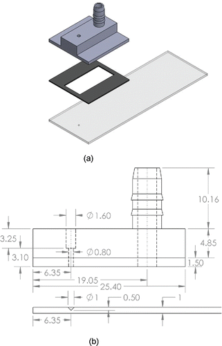
The experimental study to assess the collection efficiencies of the design is performed for several geometries and the range of operating conditions. The inlet and outlet manifold of the collector prototypes are fabricated using 3D printing techniques, and the µ-well is fabricated by the precision drilling of a microscope slide (). shows the critical dimensions of the optimized collector used in the experiments. To precisely control the final dimensions and the surface roughness of the collector nozzle, an additional finishing step is required; the dimensions of the nozzles are checked using optical microscopy for proper tolerances. The µ-well is fabricated in a standard 75 mm × 25 mm × 1 mm microscope slide using diamond cutting tools with the specified cutting angle. The wells are examined for reproducibility to confirm the dimensions. While several different geometries are tested in the preliminary study, the final choice for the µ-well is a cone shape with a diameter of 1 mm and a depth of 0.5 mm (45° angle), as shown in . A 0.5 mm thick silicone gasket provides the proper nozzle-to-plate distance, the seal between the nozzle and the impaction plate. All collectors are checked for vacuum seal before conducting the experiments.
Figure 1. (a) 3D assembly of the µ-well collector used in the experiment and (b) drawing of the collector with AF inlet used in the study (unit: mm).
The assembled collectors are tested in the aerosol chamber as shown in Figure S2 (see the online supplementary information [SI]). All reported experiments are performed at 1 slpm sampling flow rate with fluorescent monodisperse polystyrene latex (PSL) particles (Fluoresbrite® YG Microspheres, Polysciences, Inc., Warrington, PA, USA); particle sizes are 0.5, 0.75, 1, 2, and 3 µm (density 1.05 g/cm3). Three reference filters (Spectrum Poretics® polycarbonate membrane filters, 47 mm, 0.1, 0.6 um pore sizes) in open face aerosol filter holders (EDM Millipore, Billerica, MA, USA, model XX5004710) collect particles in each experiment.
A stock particle solution from the manufacturer (typically 2%–3% solid fraction) is diluted 100× in distilled water. During the experiment, about 5 mL of prepared solution is nebulized from the liquid suspension using the MADA Up-Mist™ Medication nebulizer (MADA Products, Carlstadt, NJ, USA) inside the chamber. The aerodynamic particle sizer (APS 3321, TSI, Shoreview, MN, USA) is used to verify the particle size and monitor the particle concentration in the chamber. APS measurements confirm that there is no significant aerosol agglomeration during the experiment. The typical particle concentration for particles smaller than 2 µm is between 5000 and 7000 particles/cm3. Two mixing fans inside the chamber maintain uniform particle distribution; the humidity inside the chamber is set to be 50%.
The collection efficiencies are calculated by comparing the bulk fluorescence of particles captured on the reference filters and in the collector, similar to Kesavan et al. (Citation2003). In all cases, only the particles collected in the µ-well for µ-well cases and in the defined area (about 1.5 mm in diameter) for flat plate cases are considered. To eliminate the effect of particles impacted outside the µ-well and the defined area, the area around the µ-well and the defined area is cleaned with the pointed tip wet cotton swab (22CW73, LSS, Lake Forest, IL, USA). A typical collection site for the flat plate collector before and after wiping can be seen in Figure S3 (SI), which shows that most of the particles were preserved from wiping. Although wiping can introduce some human error, the results show very high repeatability. Particles in µ-wells as well as on the reference filters are first eluted with 10 mL of 0.05% Tween 20 solution using 50 mL centrifuge tubes. The centrifuge tubes containing microscope slides and reference filters are first placed in an ultrasonic bath for 5 min, which is followed by 5 min shaking in a vortexer. Additional elution steps do not produce any significant increase in fluorescent signal. A 2 mL volume aliquot of 10 mL volume is then transferred into a 12 mm × 75 mm borosilicate glass cuvette and the solution fluorescence is measured with the spectrofluorometer (Sequoia-Turner model 450). The calibration of the spectrofluorometer and the flow meters is confirmed before and after each experiment.
Results and discussion
Effect of micro-well angle
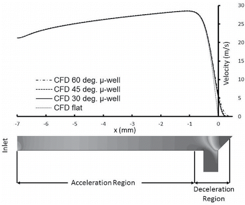
The presence of the flow recirculation zones and the uncertainty about the particle position in the flow field significantly hamper the ability to study the effect of the µ-well angle on the particle trajectories using analytical methods. One can gain insight into the details of particle behavior in the geometry using CFD simulations. The optimization study is performed for µ-well angles of 30°, 45°, 60°, and the flat collector. Figure S5 (SI) shows that the flow streamlines do not penetrate to the bottom of the well indicating the presence of the recirculation zone at the bottom of the geometry. The upper boundary of the recirculation zone is further from the nozzle for greater well angles. Figure S5 (SI) also shows an example of the 1.5 μm particles trajectories; for clarity, only the region near to the impaction plate is shown. For a particle to impact on the surface, it has to gain enough momentum in the acceleration region to overcome the drag caused by the decelerating flow approaching the impaction plate. In the µ-well, the physical dimension that the particle needs to travel increases with the well angle. This explains the similarity of particle trajectories in Figure S5c (SI) and Figure S5d (SI). shows the air velocity magnitude at the collector axis of symmetry. Air flow starts deaccelerating at the same location regardless of the angle of the µ-well. This implies that the large well angle is likely to have a lower collection efficiency or larger particle cut-off size.
Figure 2. The air velocity magnitude along the axis of impactors with different angles. The contour plot of the 45° impactor is shown on the bottom to indicate different regions.
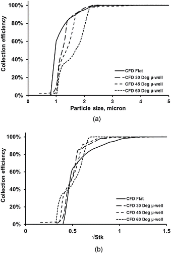
shows the comparison of the collection efficiencies from the numerical simulation for different well angles. As expected, the CFD simulation shows that the addition of the µ-well does not increase the collection efficiency due to the increased distance that particles need to travel to impact. Without considering the particle bounce and the particle trapping in the recirculation zone, the µ-well increases the cutoff size of the impactor. The collectors with 30° and 45° angles show very similar trends while the 60° collector has significantly lower collection efficiency. The data are plotted as the function of the square root of the Stokes number in . The distances from the nozzle to the bottom of the µ-well are used as the characteristic dimension in the Stokes number calculations. The data collapse onto a sigmoid curve as a function of the particle Stokes number, which validates the use of the impaction distance as the characteristic dimension in the Stokes number calculation.
Micro-well impactor with the aerodynamic focusing inlet
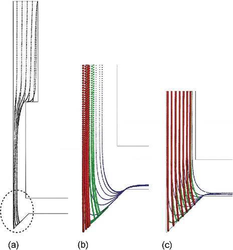
The µ-well impactor is coupled with an AF inlet to improve the collection and concentration of the collected sample in the small region. Focusing particles into the centerline of the jet allows the particles to accelerate to a higher speed, which enhances particle impaction or trapping in the recirculation zone inside the µ-well. The series of CFD simulations are used to study the effect of the AF inlet on the performance of the µ-well collector. The µ-well angle is chosen to be 45° based on the previous well angle study. The collection area is set to be 1 mm in diameter. Other dimensions of the geometry used in the simulations are listed in Table S1 (SI). The flow rates in both cases are set to be 1 slpm. The uniform velocity profile and pressure outlet boundary conditions are used in the simulation. The particle size range in the simulations is 0.4–5 µm. shows a typical result for the air streamlines in the impactor. The color map represents the air velocity magnitude in m/s. shows the trajectories of particles released from the inlet for the different impactors. The AF inlet focused particles into the center of the nozzle, which increases their speed and the collection probability. However, some larger particles (Dp > 2 µm) injected near the wall can be lost on the forward-facing step of the AF inlet reducing the collection efficiency. This can be addressed by incorporating another focusing step, which is beyond the scope of this article.
Figure 4. Gas streamlines. The color map represents the air velocity magnitude in m/s (nozzle diameter: 0.8 mm; Re = 1815).

Figure 5. Trajectories of particles in different impactors at 1 slpm. (a) Particle trajectories in the AF µ-well impactor. The dashed area is expanded in (b) to show the details; (c) detailed view of the particle trajectories for the µ-well impactor with a straight nozzle. Particle size: red line—3 µm, green line—2 µm, blue line—1 µm (nozzle diameter: 0.8 mm; Re = 1815).
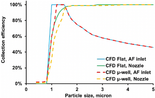
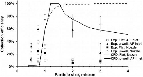
shows the plot of the calculated collection efficiencies for all four collectors. The boundary conditions and particles used in the simulations are the same as mentioned before. Particles larger than 1.5 µm have 100% collection efficiencies for the non-AF flat plate impactor. The AF flat plate impactor and non-AF flat plate impactor have nearly the same cut-off size of around 0.8 µm. However, due to the particle loss in the AF inlet, the collection efficiency decreases for particles larger than 1.5 µm. On the other hand, the AF inlet reduces the cutoff size of the µ-well impactor from 1 µm to 0.8 µm due to the increased particle speed in the nozzle centerline. The AF losses are the same as for the flat plate collector. Again, these are the results without considering particle bounce. In real life, particle bounce plays a significant role in aerosol collection, which will be demonstrated in the following section.
Experimental study for particle collection
The experimental results are presented for four geometries as seen in Figure S1 (SI). The results are compared with the numerical simulations described above. Notably, the flow field in the experiments is not perfectly axisymmetric as it is in the simulation, which may change the behavior of the flow around the µ-well. However, the effect of the non-axisymmetric flow behavior outside the collection region was found insignificant. Four impactors of the same geometry are tested in each experiment. Because the experiments focus on verifying the performance of the AF µ-well collector, the AF µ-well collection experiment is repeated at least three times to obtain 12 independent measurements for each condition. At least four independent measurements are made for other geometries to provide the comparison with the AF µ-well case.
The experimental results follow the trend of the numerical prediction for the µ-well cases. The actual collection efficiencies for the flat plate collector are dramatically different from the simulation results because of particle bounce. shows the comparison of the efficiencies from the CFD modeling and experimental data from the aerosol chamber experiments as a function of particle size. The experimental collection efficiency is higher than predicted for particles smaller than 1 µm and is lower than predicted for particles larger than 2 µm. The experimental 50% cutoff is between 0.5 and 0.74 µm, lower than the simulated CFD results, which shows the cutoff of about 1 µm. The maximum combined collection/elution efficiency is recorded for 1 µm particles (the average values are 75%). The difference in the collection efficiency between the CFD and the experiments may be due to several factors, including possible slight misalignment of the inlet with the µ-well during the assembly, potential flow instabilities that cause the flow to hug one wall and for a particle to miss the µ-well. An interesting observation is that the experimental efficiency for smaller particles is higher than when simulated by the CFD. It is likely the CFD model is not well equipped in predicting the particle-flow interaction; the turbulent dispersion-driven particle capture, which is not included in the CFD model, may also play a role if local turbulence and instabilities exist in the flow. The collection efficiency of the nozzle µ-well collector is higher than that of the AF µ-well collector. The difference can be attributed to the particle loss on the forward-facing step in the AF µ-well collector. 3 µm particles have enough inertia to penetrate through the low speed zone in the well, which makes the AF inlet act negatively on the particle collection. However, the AF inlet is necessary for µ-well to collect smaller particles.
Figure 7. Comparison of the experimental and calculated collection efficiencies of µ-well inertial impactors and the flat impactor (nozzle diameter: 0.8 mm; Re = 1815).
The primary goal of the collector design is to enable the optical interrogation of the collected aerosol in situ. The high particle density and knowledge of their location on the collection substrate is extremely important. While the CFD simulation of the particle trajectories and their interaction with the free flow is relatively straightforward, it is very challenging to model particle surface interaction because of the particle tracking schemes' limitation. The preliminary simulation that included the particle bounce model has shown that the location of particle capture is highly dependent on the bounce characteristics: angle of and particle energy lost during the bounce process. These characteristics depend on the particle and the surface properties and would not be the same for all aerosols and surfaces. Thus, in this research, we have experimentally compared the collection region for the µ-well impactor and the collection region of the flat impactor. As in the collection efficiency experiments, PSL microspheres are used. The experiments are performed in the aerosol chamber; the humidity in the chamber did not exceed 50% to ensure that the liquid menisci form at the particle deposition sites.
From the simple geometric considerations, a 45° of the well wall and a specular particle collision assumption result in the particle being reflected toward the center of the well. Any loss of the particles would be a result of a particle impacting on the outside of the well or if the well is overfilled with the collected aerosol. The latter scenario is unlikely due to the dilute nature of the atmospheric aerosols and not important from practical considerations since enough signal can be obtained if the well walls are fully coated. shows the comparison of particle collection sites of the flat plate impactor with the nozzle and AF µ-well impactor for 0.5, 1, and 2 µm particles at a 1 slpm flow rate.
Figure 8. Particle collection sites for 0.5 µm (top), 1 µm (middle), 2 µm (bottom) at 1 slpm flow rate. (a) Flat plate impactor with the nozzle; (b) µ-well impactor with the AF inlet (1 mm scale).
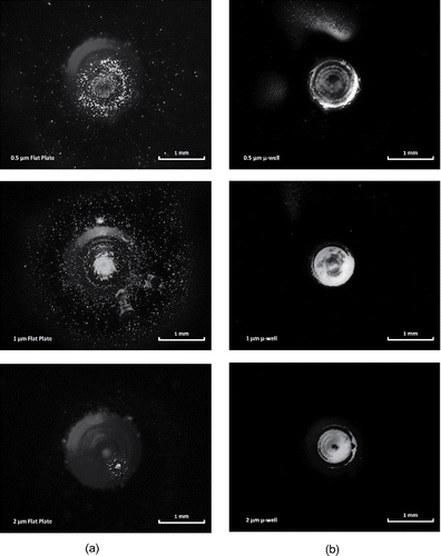
These tests compare particle deposition characteristics; PSL spheres are used. However, we expect that the trend would hold for the other particle type. Environmental and operational conditions, such as flow rate and humidity, may influence the deposition patterns. From the experiments with PSL particles, two major observations can be made:
| (i) | As designed, the combination of the AF inlet and the angle of the µ-well wall enables trapping the aerosol inside the well structure. The µ-well feature collects nearly all the particles, regardless of their size in its submillimeter diameter region, while the flat impactor has a significant dispersion of the collected aerosol. | ||||
| (ii) | The dispersion of the particles collected on the flat collector slide depends on the particle size. The 0.5 µm particles have a collection region of 1 mm diameter and significant dispersion from the center of the jet due to the bounce and jet spreading near the plate. Most of the 1 µm PSL spheres are collected in the middle, likely due to a sweet spot in the operation of the inlet; however, some dispersion is observed. The 2 µm particles show the lowest collection density, which can be explained by the increased bounce of the 2 µm particles due to their impaction velocity. | ||||
Stokes analysis of the collection efficiencies
Impactor performance can be characterized by the Stokes number, which relates the particle stopping distance to the characteristic dimension of the geometry. In general, particle trajectories for curvilinear motion have been described in Hinds (Citation1999), which uses the nozzle radius in the Stokes number calculation. The use of the nozzle radius rather than the characteristic dimension of an obstacle is based on the argument that the jet of aerosol expands only slightly until it reaches within about one jet diameter of the impaction plate. This argument is probably true for impactors with a larger nozzle-to-plate distance. However, if the impactor with the nozzle is placed close to the impaction plate, the nozzle-to-plate distance can be directly compared with the particle stopping distance, and it is more appropriate to use the nozzle-to-plate distance in the Stokes number calculation. In this work, we use nozzle-to-plate distance for the flat plate case and the distances from the nozzle to the bottom of the µ-well is used for the µ-well cases. For AF cases, the calculated magnitudes of the particle velocity on the centerline of the nozzle are used in the Stokes number calculation. The choice of the velocity is based on the observation that most of the particles are focused into the center of the nozzle by the AF inlet. shows the collection efficiency as a function of the square root of the Stokes number. The simulation data collapse onto a sigmoid curve with the cut-off √Stk ∼ 0.4 for µ-well collectors () vs. √Stk ∼ 0.49 for flat plate collectors. The shift of the cut-off curve is caused by the increase of the physical dimension the particle needs to travel before impaction.
Figure 9. Comparison of calculated and experimental collection efficiencies of impactors as a function of square root of Stokes number. (a) Flat plate impactor; (b) µ-well impactor.
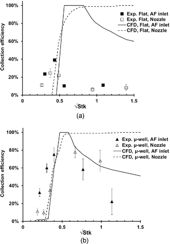
The experimental particle Stokes number is calculated in the same way as the simulation data. The flat collector exhibits reduced particle collection for the √Stk > 0.4 due to the bounce of the particles. This result is in agreement with Rennecke and Weber (Citation2013) who demonstrated the increase in bounce for particles with greater Stokes number. In addition to the particle Stokes number, the bounce characteristics depend on the particle and surface properties, as well as the environmental conditions (Chen et al. Citation2016). The µ-well collector does not have a sharp cutoff for particles with the larger Stokes numbers (higher impaction velocity magnitude); the particle bounce is redirected toward the bottom of the well, resulting in particle trapping inside the µ-well structure.
Conclusions and discussions
We designed and evaluated a novel µ-well aerosol collector combined with AF inlet for the collection of aerosols. The iterative CFD simulations are used to guide the design and optimization of the device. The modification in the collector geometry is compared with the base case of flat collection plates and straight inlet nozzles. The introduction of the µ-well by itself does not increase the performance of the collector. The effect of the µ-well angle on particle collection is studied; the simulations show that the increase of µ-well angle passed 45° resulted in adverse effects on particle collection due to the increased impaction distance. The particles on the centerline of the nozzle are more likely to be collected due to their higher magnitude of the particle velocity. Thus, the addition of the aerodynamic particle focusing before the aerosol exits the nozzle yields significant improvements in device performance. The 45° conical-µ-well coupled with AF inlet is elected to be the final collector prototype geometry. The design of the device is also based on practical considerations for sample analysis; the inlet dimensions are compatible with the pipette tip allowing for ease of sample elution. Although the elution procedure using the pipette is not discussed in the manuscript, the preliminary studies show greater than 80% elution efficiencies for biological aerosol.
The CFD simulations show that the AF µ-well collector has 50% collection efficiencies for 1 µm particles and close to 100% for particle larger than 1.5 µm particles. However, the collection efficiency starts decreasing at about 2 µm because of the particle loss in the AF inlet. Laminar flow CFD simulations under-predict the experimentally determined collector performance for smaller particles possibly due to inadequacies in the particle tracking models and the presence of unsteady flow characteristics in the µ-well.
The AF µ-well collector is able to collect highly concentrated particle samples in a 1 mm in diameter collection site. Particles stay in the well because their bounce is redirected toward the center of the well, increasing the sample collection density. The collection efficiency of the µ-well collector shows smaller dependency on the particle bounce when compared to the flat impactor. The flat collector exhibits the reduced particle collection for the √Stk > 0.4 due to the bounce of the particles. In addition to the particle Stokes number (or impaction velocity magnitude), the bounce characteristics depend on the particle and surface properties as well as the environmental conditions. The roughness of the µ-well surface may contribute to the particle collection by modifying the particle bounce characteristics. Further studies are needed to quantify the effect of surface roughness on particle collection. Sampling efficiency of the µ-well impactor is tested under relatively low particle loading scenarios. Therefore, additional work may be required to estimate collector overloading/fouling characteristics. However, our laboratory test in the highly concentrated aerosol environment (about 8000 particle/cm3 for 1 µm particles) and the preliminary environmental tests did not show significant overloading. The total volume of the µ-well is 0.13 mm3, which translates to well capacity of 130 µg. Assuming the sampling flow of 1 slpm, the collection efficiency of 50%, the aerosol concentration of 10 µg/m3, and the density of the water particle, the sample time required for completely filling the µ-well is more than 400 h of sampling. The particle packing density in the collector is not considered in the order of magnitude analysis.
The use of transparent collection substrates and well-defined collection regions independent of particle size allows for in situ optical analysis of the collected PM. This in situ spectroscopic analysis may provide a significant reduction of analysis cost and provide time-resolved information about exposure. Coupling the in situ optical analysis to standard laboratory assay may provide a good strategy for identifying exposure to chemical and biological agents, for testing for toxic industrial compounds, and for other applications. The elution volume required to recover the collected sample from the device is in the order of 10–20 µL, which provides high preconcentration of the aerosol sample for liquid assays resulting in the low limit of detection.
Nomenclature
| Nomenclatures | ||
| Cc | = | Cunningham correction factor |
| D | = | diameter of the first stage of the AF inlet (m) |
| D* | = | optimum inlet diameter (m) |
| Dc | = | characteristic dimension of the impactor (m) |
| Q | = | volumetric flowrate (m3/s) |
| Stk* | = | optimum Stokes number |
| U | = | area-average flow velocity magnitude (m/s) |
| dp | = | particle diameter (m) |
| τ | = | relaxation time (s) |
| η | = | dynamic viscosity (Pa·s) |
| ρp | = | particle density (kg/ m3) |
| ρ | = | density of the air (kg/m3) |
| ε | = | collection efficiency |
UAST_1329515_Supplementary_File.zip
Download Zip (1.4 MB)Funding
This research was funded in part by a grant from the National Institute of Environmental Health Sciences (1R21ES024715) and by a grant from the National Institute of Biomedical Imaging and Bioengineering (U01 EB021923).
References
- Arffman, A., Marjamäki, M., and Keskinen, J. (2011). Simulation of Low Pressure Impactor Collection Efficiency Curves. J. Aerosol Sci., 42(5):329–340.
- Benner, W. H., Bogan, M. J., Rohner, U., Boutet, S., Woods, B., and Frank, M. (2008). Non-Destructive Characterization and Alignment of Aerodynamically Focused Particle Beams using Single Particle Charge Detection. J. Aerosol Sci., 39(11):917–928.
- Chen, M., Romay, F. J., Li, L., Naqwi, A., and Marple, V. A. (2016). A Novel Quartz Crystal Cascade Impactor for Real-Time Aerosol Mass Distribution Measurement. Aerosol Sci. Technol., 50(9):971–983.
- Deng, R., Zhang, X., Smith, K. A., Wormhoudt, J., Lewis, D. K., and Freedman, A. (2008). Focusing Particles with Diameters of 1 to 10 Microns into Beams at Atmospheric Pressure. Aerosol Sci. Technol., 42(11):899–915.
- Dunbar, C., Kataya, A., and Tiangbe, T. (2005). Reducing Bounce Effects in the Andersen Cascade Impactor. Int. J. Pharm., 301(1–2):25–32.
- Foat, T. G., Sellors, W. J., Walker, M. D., Rachwal, P. A., Jones, J. W., Despeyroux, D. D., Coudron, L., Munro, I., McCluskey, D. K., Tan, C. K. L., and Tracey, M. C. (2016). A Prototype Personal Aerosol Sampler Based on Electrostatic Precipitation and Electrowetting-on-Dielectric Actuation of Droplets. J. Aerosol Sci., 95:43–53.
- Grinshpun, S. A., Mainelis, G., Trunov, M., Górny, R. L., Sivasubramani, S. K., Adhikari, A., Reponen, T., Mainelis, T., Trunov, T., and Górny, T. (2005). Collection of Airborne Spores by Circular Single-Stage Impactors with Small Jet-to-Plate Distance. J. Aerosol Sci., 36(5–6):575–591.
- Hinds, W. C. (1999). Aerosol Technology: Properties, Behavior, and Measurement of Airborne Particles. Wiley, New York.
- Kesavan, J. S., Doherty, R. W., and Bottiger, J. R. (2003). Performance Characterization Methods of Aerosol Samplers: Report ADA483533, Edgewood Chemical Biological Center, MD.
- Lee, J. W., Yi, M. Y., and Lee, S. M. (2003). Inertial Focusing of Particles with an Aerodynamic Lens in the Atmospheric Pressure Range. J. Aerosol Sci., 34(2):211–224.
- Liu, P., Ziemann, P. J., Kittelson, D. B., and Mcmurry, P. H. (1995a). Generating Particle Beams of Controlled Dimensions and Divergence .1. Theory of Particle Motion in Aerodynamic Lenses and Nozzle Expansions. Aerosol Sci. Technol., 22(3):293–313.
- Liu, P., Ziemann, P. J., Kittelson, D. B., and Mcmurry, P. H. (1995b). Generating Particle Beams of Controlled Dimensions and Divergence .2. Experimental Evaluation of Particle Motion in Aerodynamic Lenses and Nozzle Expansions. Aerosol Sci. Technol., 22(3):314–324.
- Marjamäki, M., and Keskinen, J. (2004). Effect of Impaction Plate Roughness and Porosity on Collection Efficiency. J. Aerosol Sci., 35(3):301–308.
- Marple, V. A., Liu, B. Y. H., and Whitby, K. T. (1974). Fluid Mechanics of the Laminar Flow Aerosol Impactor. J. Aerosol Sci., 5(1):1–IN1.
- Novosselov, I. V., and Ariessohn, P. C. (2013). Rectangular Slit Atmospheric Pressure Aerodynamic Lens Aerosol Concentrator. Aerosol Sci. Technol., 48(2):163–172.
- Novosselov, I. V., Gorder, R. A., Van Amberg, J. A., and Ariessohn, P. C. (2014). Design and Performance of a Low-Cost Micro-Channel Aerosol Collector. Aerosol Sci. Technol., 48(8):822–830.
- Park, K., Cho, G., and Kwak, J. H. (2009). Development of an Aerosol Focusing-Laser Induced Breakdown Spectroscopy (Aerosol Focusing-LIBS) for Determination of Fine and Ultrafine Metal Aerosols. Aerosol Sci. Technol., 43(5):375–386.
- Rennecke, S., and Weber, A. P. (2013). The Critical Velocity for Nanoparticle Rebound Measured in a Low Pressure Impactor. J. Aerosol Sci., 58:135–147.
- Schmechel, D., Lindsley, W. G., Chen, T. B., Blachere, F. M., Green, B. J., Brundage, R. A., and Beezhold, D. H. (2007). A Two-Stage Personal Cyclone Sampler for the Collection of Fungal Aerosols and direct ELISA and PCR Sample analysis. J. Allergy Clin. Immun., 119(1):S188–S188.
- Schreiner, J., Schild, U., Voigt, C., and Mauersberger, K. (1999). Focusing of Aerosols into a Particle Beam at Pressures from 10 to 150 Torr. Aerosol Sci. Technol., 31(5):373–382.
- Schreiner, J., Voigt, C., Mauersberger, K., McMurry, P., and Ziemann, P. (1998). Aerodynamic Lens System for Producing Particle Beams at Stratospheric Pressures. Aerosol Sci. Technol., 29(1):50–56.
- Schreiner, J., Voigt, C., Zink, P., Kohlmann, A., Knopf, D., Weisser, C., Budz, P., and Mauersberger, K. (2002). A Mass Spectrometer System for Analysis of Polar Stratospheric Aerosols. Rev. Sci. Instrum., 73(2):446–452.
- Shu, J. N., Meng, J. W., Shu, X., Zhang, Y., Gao, S. K., Yang, B., and Gan, J. (2010). Online MALDI-TOF MS Using an Aerodynamic Lens Assembly as a Direct Deposition Interface. Anal. Chem., 82(13):5906–5909.
- Tsai, C.-J., and Cheng, Y.-H. (1995). Solid Particle Collection Characteristics on Impaction Surfaces of Different Designs. Aerosol Sci. Technol., 23(1):96–106.
- Uk Lee, B., and Kim, S. S. (2002). The Effect of Varying Impaction Plate Temperature on Impactor Performance: Experimental Studies. J. Aerosol Sci., 33(3):451–457.
- Vinchurkar, S., Longest, P. W., and Peart, J. (2009). CFD Simulations of the Andersen Cascade Impactor: Model Development and Effects of Aerosol Charge. J. Aerosol Sci., 40(9):807–822.
- Willeke, K., Lin, X. J., and Grinshpun, S. A. (1998). Improved Aerosol Collection by Combined Impaction and Centrifugal Motion. Aerosol Sci. Technol., 28(5):439–456.
- Ziemann, P. J., Liu, P., Rao, N. P., Kittelson, D. B., and Mcmurry, P. H. (1995). Particle-Beam Mass-Spectrometry of Submicron Particles Charged to Saturation in an Electron-Beam. J. Aerosol Sci., 26(5):745–756.

