ABSTRACT
A water-based condensational growth channel was developed for imaging mobility-separated particles within a parallel plate separation channel of the Fast Integrated Mobility Spectrometer (FIMS). Reported are initial tests of that system, in which the alcohol condenser of the FIMS was replaced by a water-based condensational growth channel. Tests with monodispersed sodium chloride aerosol verify that the water-condensational growth maintained the laminar flow, while providing sufficient growth for particle imaging. Particle positions mapped onto particle mobility, in accordance with theoretical expectations. Particles ranging in size from 12 nm to 100 nm were counted with the same efficiency as with a butanol-based ultrafine particle counter, once inlet and line losses were taken into account.
Copyright © 2017 American Association for Aerosol Research
EDITOR:
Introduction
The size spectrum of atmospheric particles is a critical parameter to assessing their influence on cloud formation and the Earth's radiation balance. In most locations, particle size is found to be a more important factor than particle chemical composition in driving variation in the spectrum of cloud condensation nuclei (Dusek et al. Citation2006). But our knowledge of these precise spectra, especially aloft, is lacking. Although the world-wide distribution of aerosols is mapped using satellite imaging, this mapping relies on the accuracy of the models used in data retrieval, and model validation requires comparisons to directly measured, spatially-resolved, vertical profiles of aerosol size spectra (Kahn et al. Citation2004). In addition, the aerosol sizes spectrum below ∼100 nm cannot be reliably retrieved from satellite measurements, due to the low scattering/extinction cross section of small particles. Similarly, understanding the properties of aerosols near clouds (Radke and Hobbs Citation1991), or within plumes, requires detailed spatial resolution.
Obtaining these measurements aloft has been a challenge. For aircraft measurements, spatial resolution translates to time resolution. At aircraft speeds of ∼50 m/s, time scales of 1 s are desired. While optical methods have high time response, their sizing depends on particle refractive index, and the smallest particles, below 100 nm, are difficult to detect. Electrical mobility methods span a wide size range, e.g., 10 nm–600 nm, and provide valuable sizing as the mobility diameter of a singly-charged spherical particle is usually equivalent to the particle physical size, independent of refractive index or density. These methods have been used for decades for particle size distribution measurement, but are generally slow as one must step through each particle size interval. The exponential ramping approach developed by Wang and Flagan (Citation1989), which is commonly referred to as the scanning mobility particle spectrometer (SMPS), has greatly improved the speed of mobility methods. Yet it still takes more than one minute to characterize an entire size spectrum at ambient concentrations.
The more recently introduced electrometer-based mobility sizing systems measure multiple mobility sizes by placement of a series of electrometers along the collection electrode of the differential mobility analyzer (Tammet et al. Citation1998, Citation2002; Johnson et al. Citation2004). These instruments can measure complete size spectra at 1 Hz to 10 Hz, but their size resolution is limited by the multiple charging associated with the use of a unipolar charger, and the signal at lower concentrations is limited by electrometer noise (Jeong and Evans Citation2009; Asmi et al. Citation2009; Liu and Pui Citation1974). While they offer high time resolution, these currently available electrometer based instruments have neither the sizing precision nor the sensitivity for atmospheric measurements, where particle concentrations aloft are often of the order of 103 cm−3 or lower.
To meet the need for rapid, mobility-based, measurement of ambient aerosol size spectra, Kulkarni and Wang (Citation2006a,Citationb) developed the Fast Integrated Mobility Size Spectrometer (FIMS). This instrument separates particles based on electrical mobility using a parallel plate geometry, and then enlarges the particles along their trajectories through alcohol condensation so that they may be imaged. The particle positions within the gap between the parallel plates, after mobility separation and condensational growth, are captured by a digital camera operating at 10 frames/s. The images are analyzed to give the position, and hence mobility size, of each particle, from which the particle size spectrum at a time resolution of 1 Hz is derived (Olfert et al. Citation2008; Olfert and Wang Citation2009). As with the SMPS, the FIMS “neutralizes” the test aerosol using a bipolar ion source prior to mobility separation, thereby removing the ambiguity in the mobility distribution associated with the unipolar charging that is inherent to electrometer-based measurements. Importantly, because FIMS detects and counts individual particles, it is able to do so at low particle concentrations typical of the marine background. Yet due to concerns of flammability and toxicity, certification of butanol-based instruments for aircraft use is becoming increasingly more difficult.
In this article, we explore the use of water, rather than alcohol, for condensational growth in the FIMS instrument. The large diffusivity of water vapor, as compared to alcohol or air, requires significant changes in the approach. With the alcohol-based FIMS, the sheath flow is saturated with the alcohol, an approach used because of the low alcohol diffusivity. In contrast, with the water-FIMS there is no requirement to saturate the sheath flow. As a quickly diffusing species, the water vapor can be added after the mobility separator. Mobility classification can take place under dry conditions, or at ambient humidity, or at a preselected humidity, as the operator desires.
Our approach for the use of water in the FIMS system is the moderated “cool-warm-cool” architecture described by Hering et al. (Citation2014). This method removes water vapor from the flow immediately after particle activation, during the condensational growth process. By reducing the temperature, it maintains a supersaturated state while lowering the water vapor dew point. This moderated approach allows the downstream components to be operated at room temperature, without condensation. It differs from the original water-based condensation particle counters, whose output flow is warm and humid, and whose downstream optics must be heated to avoid condensation (Hering and Stolzenburg Citation2005; Hering et al. Citation2005).
Reported here is our initial evaluation of the feasibility of the use of this moderated water condensation approach in the FIMS. Our investigation focuses on two key questions: (1) whether the thermal gradients inherent in the water condensation approach disturb the particle flow trajectories in the FIMS; (2) whether a water-based system could provide distinct and well-resolved particle images required for particle size distribution measurement. These questions were explored experimentally using a “preliminary” water-FIMS system that was mated to the existing FIMS mobility separator, camera and optics. As a feasibility study, this work used as many existing components of the butanol-based FIMS as was possible. Subsequent efforts led to the development of a completely new water-FIMS system with a redesigned mobility separator and growth channel. This newer system expands the mobility separation window through use of newly designed, multivoltage electrode Pinterich et al. (Citation2017a). The growth channel in this newer system allows mobility classification to be done over a wide range in relative humidity, opening the door to rapid measurement of particle hygroscopicity (Pinterich et al. Citation2017b).
Experimental methods
Preliminary water-FIMS system
The preliminary water-FIMS system tested here is illustrated in . The system consists of three primary components: the mobility separator, the water condensation growth channel, and the optical illumination and detection system. The mobility separator is from the alcohol FIMS system, with a gap of 11 mm, a width of 127 mm and an electrode length (in the direction of flow) of 111 mm. It uses a single voltage electrode, such that the electric field is uniform throughout the mobility separation region (Kulkarni and Wang Citation2006b). The water condensation growth channel was custom made to mate to the mobility separator. It also uses a parallel plate geometry, with the same gap spacing and width as the separator.
Figure 1. Schematic of the water-FIMS system, showing mobility separator, water condensation growth channel and detection zone. The system uses a parallel plate geometry. In this sketch the gap dimension has been greatly magnified with respect to the length.
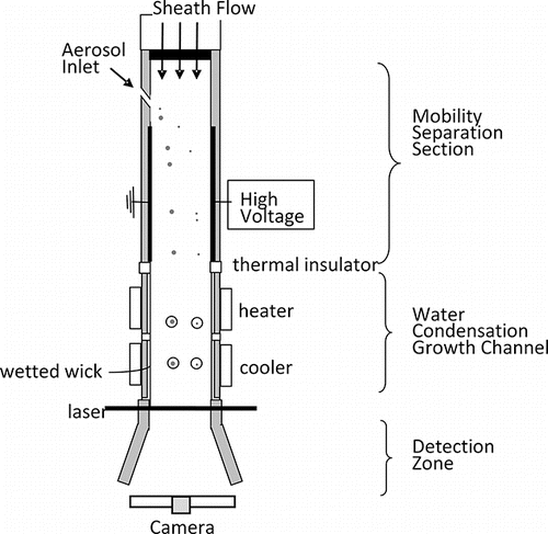
Aerosol at a flow rate of 0.3 L/min is introduced through a narrow slit along the ground plane into a 13 L/min sheath flow. Charged particles migrate across the sheath flow due to the electric field in the separation channel. The potential on the high voltage electrode was set to either −40 V, −100 V, or −700 V. Those particles that are most mobile travel the furthest distance across the channel. Once exiting the separator, the particles continue to travel along their same flow trajectories. As the flow passes through the condensation growth channel, these particles grow to form droplets several micrometers in diameter. These droplets are illuminated with a sheet of laser light, and imaged onto a CCD camera.
Design of the condensation growth channel
A CAD of the system of our growth channel is shown in . In this preliminary system, which was designed for laboratory use only, the flow is conditioned in the mobility separator, which operated at laboratory temperature with a partially humidified sheath flow. Unlike the conditioner of a water-condensation particle counter, its walls are not wetted. This is followed by a warm, wet-walled “initiator” section that creates the supersaturation necessary for particle activation. The final section is a cool, wet-walled “moderator” that maintains the supersaturation for droplet growth while reducing the water vapor content. Thermal isolation between the initiator and mobility separator is provided by an active insulator that is cooled to the temperature of the mobility separator by means of a thermo-electric cooler. The initiator and moderator have separate, ¼ inch thick alumina wicks and water fill systems. The walls of the initiator are heated by means of cartridge heaters, and the active insulator and moderator are equipped with thermo-electric devices for cooling. The optical components, taken from the alcohol FIMS system, are mounted downstream of the moderator. The gap (11 mm) and width (127 mm) match that of the mobility separator. The total length of the growth channel, excluding optics section, is 240 mm. Temperatures were controlled by programmable on-off controllers (Tecnologic TLZ10, Farnsborough, Hampshire, UK).
Figure 2. CAD image of the water condensation growth channel showing the Active Insulator, Initiator, Moderator, and Optics. Temperature control is provided by thermo-electric devices and cartridge heaters. Wicks are held in place by threaded clamps (green) and self-sealing bolts (not shown) and sealed by o-rings.
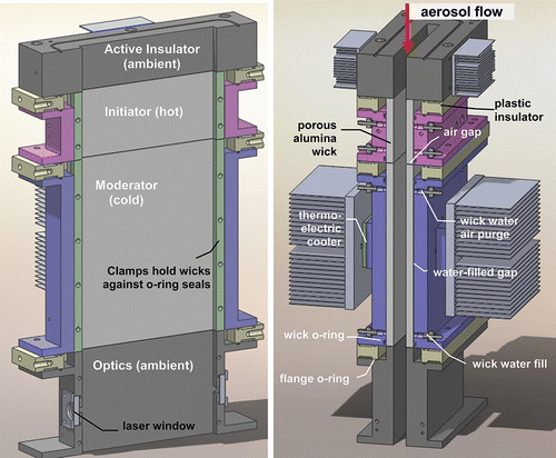
The initiator and moderator wicks are wetted using a syphoned approach that eliminates protrusions into the flow channel. Water is supplied by to the wicks through the water fill port at the lower end of each wick, which is connected to a reservoir bottle placed at least 10 cm below the level of the wick and vented to the aerosol inlet. The wick water air purge is used to pull water up the wick channel (labeled “water-filled gap”) and is then sealed, creating a pressure that is lower than the instrument inlet pressure by the height difference between the wick and reservoir bottle. This new passive water feed system eliminates protrusions into the flow, and is effective both in adding wick water to the warmed initiator, as well as removing excess wick water from the cooled moderator. However, it does require a wick bubble point of greater than the pressure head corresponding to the distance between the water reservoir and the top of the wick.
Measurement of droplet size
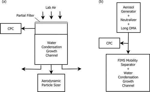
The size of droplets formed by the growth channel, independent of the mobility separator, was measured using partially filtered ambient laboratory air and an aerodynamic particle sizer (APS, Model 3321, TSI Inc., Shoreview, MN, USA), as illustrated in . Laboratory air was drawn through a piece of Whatman-41 filter paper placed over the inlet of the open channel. This served as a poor fine-particle filter that both reduced the input particle concentrations, and laminarized the flow. The upstream concentration, at the inlet of the growth cell but below the filter paper, was measured using a water-condensation particle counter (WCPC, TSI Model 3787). Downstream droplet size and concentration was measured by the APS. An adapter piece constructed specifically for this experiment joined the center of the parallel plate flow to the APS sampling at 1 L/min, while the remaining flow was balanced between outer two sections. Measurements were done at input particle concentrations of ∼1000/cm3, which is within acceptable operating bounds of the APS, and are more representative of that expected downstream of the mobility sizing system.
System evaluation
To evaluate the laminar character of the flow, the dependence of particle position on particle size; and the size-dependent detection efficiency, the water-FIMS system was tested with monodisperse aerosol. Sodium chloride aerosol was generated through atomization, charge-neutralized using a bipolar ion source, and size-selected using a standard long-column mobility analyzer (DMA, TSI Model 3081), as shown in . The DMA output of positively charged, uniform electrical mobility particles were sampled by the FIMS and by a condensation particle counter (TSI Model 3025), operated in parallel. The condensation particle counter served as reference for the total input particle concentrations. The mobility separator, active insulator and optics were at room temperature of ∼22°C. The initiator and moderator were operated at temperatures of 55°C and ∼11°C, respectively. The aerosol flow was 0.3 L/min, and the total (aerosol plus sheath) flow was 13 L/min. Imaging and data processing was done using the FIMS camera and software developed for the standard alcohol-based FIMS.
Results
Droplet size
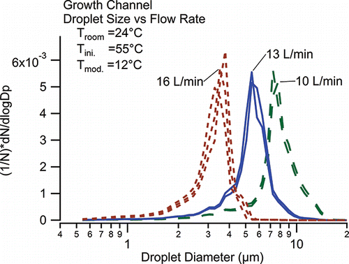
Measured size spectra of the droplets exiting the growth cell, when challenged with diluted ambient air, are presented in . Data were obtained at several sets of operating temperatures, and flow rates. Shown are results for an initiator temperature of 55°C, as used in subsequent measurements. At 13 L/min flow these conditions produced 5–6 µm droplets. Importantly, the droplet concentration measured by the APS was comparable to the upstream concentration measured by the WCPC, with a mean ratio of APS to WCPC concentration of 0.98 ± 0.02, indicating efficient activation of particles penetrating our Whatman-41 pre-filter.
Laminar flow and imaging
The most critical question addressed in this feasibility study is whether the water-based growth channel maintains smooth, laminar flow, with sufficient particle growth across the width of the parallel plates to image the particles. This was tested by inspecting the images produced by monodispersed sodium chloride aerosols. With the single electrode design, particles of uniform mobility are expected to form a straight line, representing their position in the gap at the end of the mobility separator. As shown in , we found clear, sharply aligned particles forming a well-defined line. In these images the ground electrode, where particles are introduced, is aligned with the left side, and the high voltage electrode is on the right. For the more mobile particles, position of the line of particles shifts towards to the right, towards the high voltage electrode.
Figure 5. Images obtained from CCD of 100 nm, 65 nm, and 42 nm DMA classified NaCl particles in the prototype water-FIMS. Gray lines indicate the edges of the separation channel (i.e., the electrode surface). The ground plane, along which the particles are introduced at the top of the separator, is on the left; the high voltage electrode is on the right.
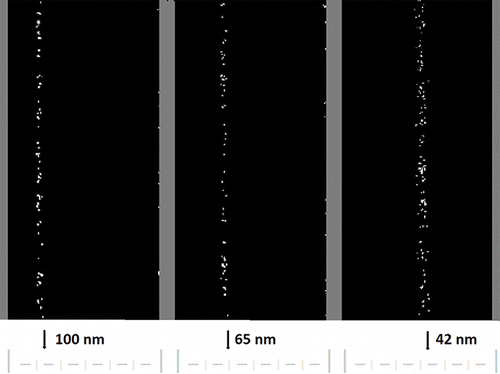
An exciting aspect of this system is the ability to view the particle positions within the mobility separator in real time. As the upstream DMA selection voltage is adjusted to shift from one particle size to the next, the change in the input particle size produces a shift in particle position that can be directly viewed. Indeed, it is reminiscent of watching an amateur chorus line, all perfectly aligned until given the signal to move, then advancing in a somewhat ragged manner until realigning themselves neatly and precisely in their new positions. A movie clip is provided in the online supplementary information.
Particle position
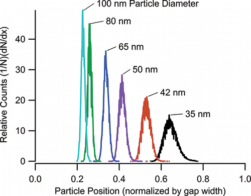
is a histogram plot of the normalized particle concentration as a function of position for six different mobility sizes tested. These data were collected for operation with 0.3 L/min aerosol flow, 13 L/min sheath flow and 700 V separation potential. The largest particles, at 100 nm, are on the left, near the position where the aerosol is introduced. The smaller particles travel further across the sheath flow and are found on the right. The peaks are all clearly separated. The width of each peak is a measure of the combined resolution of the DMA used upstream and that of the water-FIMS. DMA-classified particles have a finite range of mobility, and the spread in their position increases with the distance travel in the direction of electric field (i.e., particle position).
Figure 6. Histogram of particle concentrations vs. position in the mobility separator for 6 sizes of monodisperse sodium chloride aerosols. Aerosol and sheath flows were 0.3 L/min and 13 L/min, respectively. The mobility separator was operated at 700 V.
To relate the particle position to particle electrical mobility, we calculate the fraction of flow traversed by the particle from the midpoint in the aerosol flow to its mean final position, x. This is calculated as [Q(x)-0.5Qa]/[Qa+Qsh], where Q(x) is the total flow between the ground plane (x = 0) and the mean particle position x, and where Qa and Qsh are the aerosol and sheath flow (Flagan Citation1999, or Equation 19 of Kulkarni and Wang Citation2006a). One expects a linear dependence of mobility on this parameter. As shown in , the water-FIMS shows that the measured particle position shifts with particle mobility diameter such that the fraction of flow traversed by the particle varies linearly with the particle mobility.
Figure 7. Particle mobility vs. fraction of flow traversed by the particle for the data of . Error bars are calculated from the peak width at half-height. A linear relationship is observed, as predicted by theory.
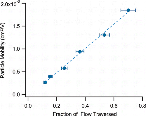
The error bars in are the uncertainty in the enclosed flow calculated from the spread in particle position at half-height. The measured width reflects the combined transfer function from the long DMA used to generate the aerosol, and from the water-FIMS. We note that the observed width from the water-FIMS, which is approximately 10% of the mobility, is what is expected of the upstream DMA for non-diffusing particles, as it was operated with a 10:1 ratio of sheath to aerosol flow. This means that the precision of the water-FIMS is at least comparable to that of the DMA. More detailed analysis would be required to resolve the water-FIMS transfer function (Kulkarni and Wang Citation2006a,Citationb).
As with the alcohol-based FIMS system, data analysis is confined to particles detected between 0.2 and 0.8 channel widths, which encompasses 80% of the enclosed flow. Near the ground electrode the mobility resolution is low, as the ratio of enclosed sheath flow to aerosol flow is small (Kulkarni and Wang Citation2006b). Near the high voltage electrode, where the smallest particles are found, the condensational growth becomes ineffective. This is because the peak supersaturation along these near-wall flow trajectories is lower, approaching a value of 1.0 at the wall. Additionally, the time response for particles traveling near the channel walls is slow due to the parabolic flow profile.
Detection efficiency
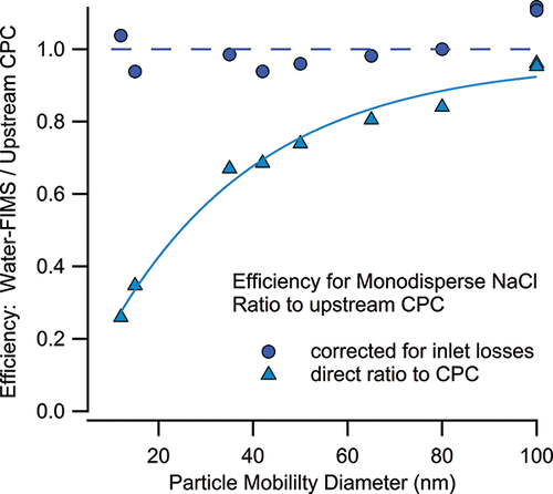
The particle detection efficiency for this feasibility prototype water-FIMS is shown in . The water-FIMS detection efficiency is calculated as the ratio of the particle concentration measured by the water-FIMS to the concentration measured by the TSI Model 3025 condensation particle counter. Data at particle sizes from 35 to 100 nm were obtained at a fixed operating voltage (700 V), while those for the smaller sizes were classified using lower voltages of 40 to 100 V. Water-FIMS data are corrected for transport losses in the mobility separator inlet slit and the upstream tubing (Olfert, private communication). With this correction the mean water-FIMS detection efficiency was 100 ± 6% across all sizes measured, from 12 nm to 100 nm. However, we caution that this close agreement is a bit fortuitous, as the correction for transport losses was large, ranging from 20% at 60 nm, to 50% at 20 nm. Both corrected and uncorrected efficiencies are shown in .
Conclusions
These data demonstrate the feasibility of the water-based FIMS approach. Using the moderator stage following the initiator eliminated water condensation on the camera optics, by reducing the dew point of the exiting flow. Using the syphoned wick approach eliminated protrusions into the flow channel, yet provided wetted walls as required. The droplet size produced, as measured by an APS, was 5–6 µm, and adequate for imaging within the FIMS system. For sodium chloride test aerosols ranging from 12 nm–100 nm, the imaged particles fell in straight lines. This demonstrated that the laminar flow is maintained during the growth process, such that the particle positions captured by the camera as the droplets exit the growth cell is the same at the bottom of the separator. Finally, for all particle sizes tested, an average 100 ± 6% of all particle sizes tested were activated. Based on these results, efforts have been made to incorporate the water condensation channel into a wide-range, water-FIMS system that uses a multiple electrode separator (Wang Citation2009) to provide dry particle sizing from 8 nm to 580 nm in a single snapshot (Pinterich et al. Citation2017a), and to rapidly measure particle size change upon humidification (Pinterich et al. Citation2017b).
UAST_1338338_Supplementary_Files.zip
Download Zip (1.1 MB)Funding
This research was supported by the Department of Energy under SBIR/STTR grants DE-SC0006312 and DE-SC0013103. The views and opinions of authors expressed herein do not necessarily state or reflect those of the United States Government or any agency thereof.
References
- Asmi, E., Sipilä, M., Manninen, H. E., Vanhanen, J., Lehtipalo, K., Gagné, S., … Uin, J. (2009). Results of the First Air Ion Spectrometer Calibration and Intercomparison Workshop. Atmos. Chem. Phys., 9(1):141–154.
- Dusek, U., Frank, G. P., Hildebrandt, L., Curtius, J., Schneider, J., Walter, S., Chand, D., Drewnick, F., Hings, S., Jung, D., Borrmann, S., and Andreae, M. O. (2006). Size Matters More Than Chemistry for Cloud-Nucleating Ability of Aerosol Particles. Science, 312:1375–1378.
- Flagan, R. C. (1999). On Differential Mobility Analyzer Resolution. Aerosol Sci. Technol., 30:556–570.
- Hering, S. V., and Stolzenburg, M. R. (2005). A Method for Particle Size Amplification by Water Condensation in a Laminar, Thermally Diffusive Flow. Aerosol Sci. Technol., 39(5):428–436.
- Hering, S. V., Stolzenburg, M. R., Quant, F. R., Oberreit, D. R., and Keady, P. B. (2005). A Laminar-Flow, Water-Based Condensation Particle Counter (WCPC). Aerosol Sci. Technol., 39(7):659–672.
- Hering, S. V., Spielman, S. R., and Lewis, G. S. (2014). Moderated, Water-Based, Condensational Particle Growth in a Laminar Flow. Aerosol Science and Technology, 48(4):401–408.
- Jeong, C.-H., and Evans, G. J. (2009). Inter-Comparison of a Fast Mobility Particle Sizer and a Scanning Mobility Particle Sizer Incorporating an Ultrafine Water-Based Condensation Particle Counter. Aerosol Sci. Technol., 43:364–373.
- Johnson, T., Caldow, R., Pocher, A., Mirme, A., and Kittelson, D. (2004). A New Electrical Mobility Particle Sizer Spectrometer for Engine Exhaust Particle Measurements. SAE 2004 World Congress & Exhibition, SAE-2004-01-134, Detroit, MI.
- Kahn, R., Anderson, J., Anderson, T. L., Bates, T., Brechtel, F., Carrico, C. M., Clarke, A., Doherty, S. J., Dutton, E., Flagan, R., Frouin, R., Fukushima, H., Holben, B., Howell, S., Huebert, B., Jefferson, A., Jonsson, H., Kalashnikova, O., Kim, J., Kim, S. W., Kus, P., Li, W. H., Livingston, J. M., McNaughton, C., Merrill, J., Mukai, S., Murayama, T., Nakajima, T., Quinn, P., Redemann, J., Rood, M., Russell, P., Sano, I., Schmid, B., Seinfeld, J., Sugimoto, N., Wang, J., Welton, E. J., Won, J. G., and Yoon, S. C. (2004). Environmental Snapshots from ACE-Asia. J. Geophys. Res., 109:D19S14.
- Kulkarni, P., and Wang, J. (2006a). New Fast Integrated Mobility Spectrometer for Real-Time Measurement of Aerosol Size Distribution—I: Concept and Theory. J. Aerosol Sci., 37:1303–1325.
- Kulkarni, P., and Wang, J. (2006b). New Fast Integrated Mobility Spectrometer for Real-Time Measurement of Aerosol Size Distribution—II: Design, Calibration, and Performance Characterization. J. Aerosol Sci., 37:1326–1339.
- Liu, B. Y. H., and Pui, D. Y. H. (1974). A Submicron Aerosol Standard and the Primary, Absolute Calibration of the Condensation Nuclei Counter. J. Colloid Interface Sci., 47:155–171.
- Olfert, J. S., Kulkarni, P., and Wang, J. (2008). Measuring Aerosol Size Distributions with the Fast Integrated Mobility Spectrometer. J. Aerosol Sci., 39:940–956.
- Olfert, J. S., and Wang, J. (2009). Dynamic Characteristics of a Fast-Response Aerosol Size Spectrometer. Aerosol Sci. Technol., 43:97–111.
- Pinterich, T., Spielman, S. R., Hering, S. V., and Wang, J. (2017a). A Water-Based Fast Integrating Mobility Spectrometer (WFIMS) with Wide Dynamic Size Range. Aerosol Sci. Technol. DOI: 10.1080/02786826.2017.1338664.
- Pinterich, T., Spielman, S. R., Hering, S.V., and Wang, J. (2017b). Humidity-controlled Fast Integrated Mobility Spectrometer (HFIMS) for Rapid Measurements of Particle Hygroscopic Growth, Atmos. Meas. Tech. Discuss., https://doi.org/10.5194/amt-2017-180
- Radke, L. F., and Hobbs, P. V. (1991). Humidity And Particle Fields Around Some Small Cumulus Clouds. J. Atmos. Sci., 48:1190–1193.
- Tammet, H., Mirme, A., and Tamm, E. (1998). Electrical Aerosol Spectrometer of Tartu University. J. Aerosol Sci., 29:S427–S428.
- Tammet, H., Mirme, A., and Tamm, E. (2002). Electrical Aerosol Spectrometer of Tartu University. Atmos. Res., 62:315–324.
- Wang, J. (2009). A Fast Integrated Mobility Spectrometer with Wide Dynamic Size Range: Theoretical Analysis and Numerical Simulation. J. Aerosol Sci., 40:890–906, doi:10.1016/j.jaerosci.2009.06.005
- Wang, S. C., and Flagan, R. C. (1989). Scanning electrical mobility spectrometer. J. Aerosol Sci., 20:1485–1488.

