ABSTRACT
A water-based fast integrated mobility spectrometer (WFIMS) with enhanced dynamic size range is developed. The WFIMS builds on two established technologies: the fast integrated mobility spectrometer and laminar flow water-based condensation methodology. Inside WFIMS, particles of differing electrical mobility are separated in a drift tube and subsequently enlarged through water condensation. Particle size and concentration are measured via digital imaging at a frame rate of 10 Hz. By measuring particles of different mobilities simultaneously, the WFIMS resolves particle diameters ranging from 8 to 580 nm within 1 s or less. The performance of WFIMS was characterized with differential mobility analyzer (DMA) classified (NH4)2SO2 particles with diameters ranging from 8 to 265 nm. The mean particle diameters measured by WFIMS were found to be in excellent agreement with DMA centroid diameters. Furthermore, detection efficiency of WFIMS was characterized using a condensation particle counter as a reference and is nearly 100% for particles with diameter greater than 8 nm. In general, measured and simulated WFIMS mobility resolutions are in good agreement. However, some deviations are observed at low particle mobilities, likely due to the non-idealities of the WFIMS electric field.
Copyright © 2017 American Association for Aerosol Research
EDITOR:
1. Introduction
In the last decades, the role of atmospheric aerosol particles in determining the earth's radiative budget, climate change, and air quality has been recognized. In this context, the characterization of spatial and temporal variations of particle number size distributions, especially in the nanometer size range, is essential. Real-time measurements of particle size distributions are often required to capture highly dynamic aerosol processes, such as atmospheric new particle formation. In addition, measurement of spatial and temporal variations of aerosols onboard fast-moving platforms, such as aircrafts, also requires high time resolution. Capture of aerosol dynamics occurring on very small time scales requires instrumentation that, inter alia, has high sizing-accuracy, a wide size range, high time resolution, and good counting statistics.
One of the most widely used instruments for particles below about 500 nm is scanning mobility particle sizer (SMPS). The SMPS sequentially measures particle number concentrations within a narrow size (mobility) range. To obtain entire particle size distributions, an SMPS scans over a wide range of classifying voltages. This yields high sizing accuracy in a wide size range. However, the scanning process typically takes a few minutes (Flagan Citation1999). Wang et al. (Citation2002) reduced the scanning time to 1–2 s by using a fast-response detector. However, particularly in clean environments the scanning time remains limited by the time required to obtain statistically relevant data. Other instruments based on electrical mobility classification, such as the electrical aerosol spectrometer (Mirme et al. Citation1984, Citation1994; Tammet et al. Citation1998, Citation2002), the engine exhaust particle sizer (Johnson et al. Citation2004), and the differential mobility spectrometer (Biskos et al. Citation2005) achieve high time resolution by measuring different mobilities simultaneously using an array of integrated electrometers. However, the low sensitivity of those detectors limits measurements to highly concentrated aerosols, such as engine exhausts. The differential mobility analyzer train (DMA-train; Winkler et al. Citation2013) achieves high time resolution in the 3 to 10 nm size range by operating a set of DMAs in parallel. While this approach offers faster measurement speed at atmospheric relevant particle number concentrations, the size resolution, determined by the number of DMAs, is comparatively low.
A heptanol-based fast integrated mobility spectrometer (FIMS) with wide dynamic size range was recently developed (Wang et al. Citation2017a,b). Covering the 8 to 600 nm particle diameter range in a single snapshot, FIMS provides high-resolution, 1 s size distribution measurements. The heptanol FIMS consists of a drift channel to spatially separate particles of differing electrical mobility, a condensational growth channel, and an optical particle detector. Heptanol vapor is introduced with the sheath flow in the separator. Mobility-separated particles are enlarged through condensational growth along their flow trajectories, and their positions within the channel are captured via digital imaging. Thus, FIMS combines the precision of electrical mobility sizing with the speed and sensitivity of optical particle counting.
In this article, we present the performance characterization of a new water-based FIMS (WFIMS), which combines measurement speed and precision of the heptanol-based FIMS with the water-based condensation methodology (Hering et al. Citation2005; Hering and Stolzenburg Citation2005; Spielman et al. Citation2017). Using water, rather than heptanol, to grow particles for detection has several advantages. First, WFIMS allows measurements in environments where chemicals such as heptanol are prohibited (e.g., clean rooms). In WFIMS, the mobility separation can be accomplished at a range of relative humidity (RH), allowing measurements of particle hygroscopicity when WFIMS is used in tandem with a DMA (Pinterich et al. Citation2017). Other practical advantages of using WFIMS rather than FIMS are that certification and transport of water-based instruments is much easier, and there are essentially no occupational health concerns related to their operation.
2. Instrument design
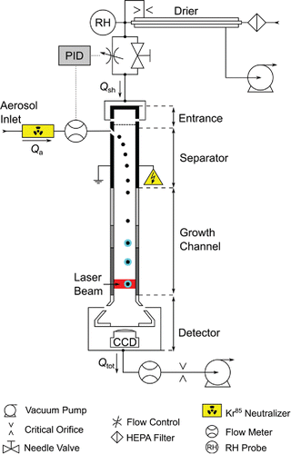
The WFIMS consists of four main sections, namely: entrance, separator, growth channel, and detector (). As with its predecessor FIMS (Kulkarni and Wang Citation2006a,b), a parallel plate geometry defines a rectangular flow channel with a cross-sectional area in the (x,y)-plane. In this study, we have adopted the same coordinate system used in Figure 1 of Wang (Citation2009), which differs from the one used in Kulkarni and Wang (Citation2006a,b). Particle-free sheath air is first dried using a nafion drier (Perma Pure LLC, Lakewood, NJ, USA, PD-200T-24MSS) before it enters the channel through two opposing ports located at the top of the entrance section. Subsequently, the sheath flow is evenly distributed using a laminarizing mesh. The aerosol flow enters the main channel through a narrow slit (0.03 cm × 12.7 cm) along the y-direction in the grounded electrode (left electrode in ) of the separator. The gap of the channel is reduced from 1.12 cm as in the heptanol FIMS (Wang et al. Citation2017a) to 0.9 cm in order to eliminate the flow instability due to buoyancy generated by heating of the flow in the growth channel (see more details about the growth channel below). Hence, WFIMS channel cross-section is now 0.9 cm × 12.7 cm and operates at 16.5 l/min of total flow (a detailed table listing key physical and operation parameters of WFIMS can be found in the online supplementary information [SI], S.1). Constant total flow Qtot through the channel is achieved by a vacuum pump along with a critical orifice (O'Keefe Controls Co., Trumball, CT, USA, No. 55). The desired aerosol flow Qa, measured with a laminar flow element (capillary tube with ID ∼ 0.13 cm) and a differential pressure transducer (Omega Engineering, Inc, Noralk, CT, USA, PX653-01D5V), is maintained via PID control of the sheath air flow Qsh using a proportional solenoid control valve (MKS Instruments Inc., Andover, MA, USA, 0248A). At standard operating conditions, the flow ratio Qa/Qsh is set at about 0.02.
Figure 1. Schematic diagram of the water-based fast integrated mobility spectrometer (WFIMS) (side view: (x,z)-plane, the y-axis is pointing out of the paper).
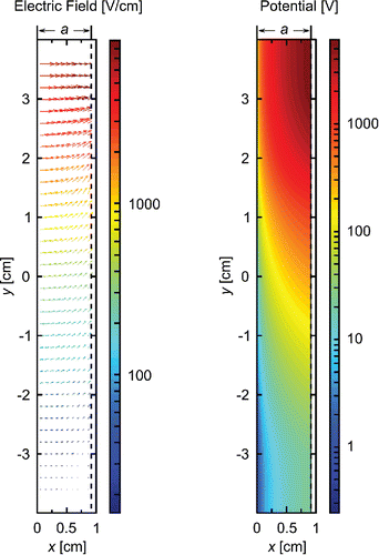
The same electrode as in the FIMS using heptanol as working fluid (Wang et al. Citation2017a) is employed here. The HV electrode is made of a PCB board, which is positioned in the (y-z)-plane and consists of 61 straight copper traces running in z-direction (i.e., the direction of flow). The applied voltage increases exponentially with the y position of the trace from V1 = 20 V at y = −3 cm to 1800 V, then linearly from 1800 to V2 = 6000 V at y = +3 cm, such that the maximum voltage difference among adjacent traces is limited to 300 V to avoid arcing. Minimum and maximum voltages V1 and V2 are applied from y = −6 to −3 cm and from +3 to +5 cm, respectively. The spatially varying electric field generated by the HV electrode is simulated using COMSOL Multiphysics™, and presented in . Note the electric field is assumed to be independent of z-coordinate (the flow direction), and this assumption will be further discussed later. The spatially varying electric field provides two-dimensional size separation of aerosol particles in the (x,y)-plane. At the exit of the separator, the positions of monodispersed particles form an arc in the cross-section of the channel, i.e., (x,y)-plane, instead of a straight line in the FIMS employing a uniform electric field (Kulkarni and Wang Citation2006a). Forming an arc trajectory itself does not have any advantage over a straight line for monodispersed particles. An arc trajectory for monodispersed aerosol is a result of spatially varying electric field (i.e., the strength of electric field varies with y position), which is necessary to enhance the dynamic size range of the WFIMS. Particles with higher mobility are distinguished at the bottom end (y < 0) of the channel and lower mobility particles at the top ( and ). To avoid edge effects of the electric and flow fields, particle detection is limited to −3.5 cm ≤ y ≤ +3.5 cm ().
Figure 2. Electric field vectors (a) and equipotential lines (b) between separator electrodes. Both the length and the color of the field vector scale with the logarithm of the electric field strength. The gap a between separator electrodes is 0.9 cm (bottom view: (x,y)-plane).
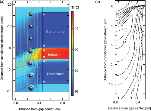
After being positioned by the separator, particles enter a water-based condensational growth channel. In contrast to FIMS, the WFIMS introduces the vapor needed for particle condensational growth after the mobility separation, an option made more practically feasible by the high diffusivity of water vapor. Thus, the relative humidity within the mobility separation region may be controlled independently. Typically, WFIMS is operated with low humidity in the separator, thereby providing dry, mobility-based particle sizing. The growth channel has three stages (): a cold “conditioner,” to cool and humidify the aerosol; a warm “initiator” to introduce water vapor, leading to a supersaturation; and a cold “moderator.” The moderator technique is described in Hering et al. (Citation2014), which shows that once the supersaturation is created by the warm, wet walls of the initiator section, the saturation profiles are fairly insensitive to a downstream decrease in the wall temperature, provided the walls are wet. The purpose of the moderator section is to lower the dew point so that the exiting air does not fog the camera window and other components, while allowing the supersaturation and growth to persist. The conditioner and moderator sections are operated below the temperature inside the separator, while the initiator is warmer. The smallest particle size that is activated to grow is primarily dependent on the maximum supersaturation inside the growth channel, which is largely controlled by the difference between the initiator and conditioner temperatures. The dew point of the flow exiting the growth channel depends mostly on the moderator temperature. shows contour plots of modeled water vapor saturation ratio (solid lines) and equilibrium Kelvin diameter (dashed lines), which we use to approximate the diameter of the smallest particle that can be activated, inside the growth channel. Vapor supersaturation is achieved in most of the initiator-moderator region, and peak saturation ratios higher than 1.4 occur in the central region just downstream of the initiator exit, at axial positions ranging from about 5 to 7 cm. The equilibrium Kelvin diameter in this region, which corresponds to the central 50% of the viewing window, is 5.5 nm and smaller. The contour line representing a Kelvin diameter of 7 nm indicates that particles down to that size could be activated within the entire viewing window.
Figure 3. (a) Temperature profile inside the growth channel showing flow stream lines (white) and relative humidity contours (black). (b) Contour plot showing modeled water vapor saturation ratio (solid lines) and equilibrium Kelvin diameter (dashed lines) inside the growth channel. The (warm) initiator extends from 0 to 5.1 cm. The laser position is 12.4 cm (side view: -plane).
To preserve the (x,y) positions of particles as they grow, flow obstructions within the growth channel were minimized by fabricating wicks from 0.6 cm thick sheets of alumina bisque, a porous partially fired ceramic, one pair for each section of the growth channel. They form channel walls that are flat to within about 50 μm. Additionally, the stiffness of the alumina allows the wicks to be held in place only by clamps at the edges of the channel. Each of the six wicks is clamped against an O-ring to create a thin, air-tight, water-filled reservoir against the aluminum housing. Water is drawn up into the reservoirs from a reservoir about 30 cm below the bottom of the growth channel. The resulting negative pressure prevents water from dripping into the flow channel, without the need for a physical barrier. The wick surfaces are completely saturated; any excess water is quickly drawn inside the porous material, but surface tension prevents air from entering (Baker Citation2012). At the end of the growth channel, grown droplets are illuminated with a sheet laser beam (Coherent, Santa Clara, CA, USA, Mag II, λ = 680 nm). The image of the illuminated droplets is captured using a focusing lens (Nikon, Minato, Tokyo, Japan, NIKKOR 50 mm) and a CCD camera (Teledyne Dalsa Inc., Waterloo, ON, Canada, Pantera 1M60) operated with a frame rate of 10 Hz.
3. Image processing and transfer function simulation
Particle sizes and number concentrations are determined by processing images acquired with the CCD camera. To this end, positions of individual particles are derived from recorded camera frames using MATLAB's Image Processing Toolbox. Measured particle positions () are then converted to instrument response mobilities Zp* through interpolation using a map of instrument response mobilities () derived from simulated trajectories (Wang Citation2009; Wang et al. Citation2017a). Finally, instrument response mobilities are converted into instrument response diameters Dp* assuming singly charged particles ().
Figure 4. (a) CCD image of DMA classified (NH4)2SO4 particles (Dp = 80 nm). The white rectangle indicates the viewing window. (b) and (c) show maps of instrument response mobilities Zp * and corresponding instrument response diameter Dp* of singly charge particles at the exit of the separator, respectively. (b) and (c) are based on particle trajectory simulations.
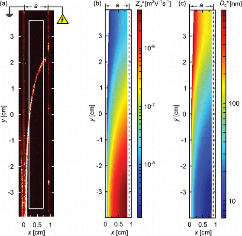
Instrument response mobilities Zp* are mapped using the simulated positions at the separator exit for non-diffusing particles introduced along the central aerosol flow stream line. Note for non-diffusing particles, these positions are essentially the same as those detected following growth. The simulation of particle trajectories was carried out for particles of 2500 diameters evenly spaced on a logarithmic scale from 4 to 900 nm. Particles of each size were introduced into the separator at 1001 locations yin evenly spaced from y = −4.00 cm to +4.00 cm along the central aerosol flow streamline. The velocity and trajectory of each particle inside the separator was calculated from the particle electrical mobility, the electric field, and the flow field. The flow field is assumed to be fully developed, with a parabolic profile and non-zero component only in the z-direction. WFIMS transfer functions are based on simulated trajectories of particles introduced along 101 aerosol flow streamlines evenly spaced between the boundaries of the aerosol flow, and at 1001 y positions along the width of the inlet. Brownian motion of particles was simulated using Monte Carlo techniques, and for particles introduced at several flow stream lines and y positions, the simulation was repeated 10 times (Wang et al. Citation2017a). These resulted in the simulation of about 106 trajectories for each particle size. The Brownian motion of particles was simulated beyond the separator, until the point of particle activation in the growth channel. Particle trajectories were actually calculated until 2.5 cm after the beginning of the initiator representing the upper limit for the impact of diffusion on particle positions. We assume that the contour line corresponding to a Kelvin equilibrium diameter of 7 nm in represents the maximum distance La particles travel between the end of the electrode and the point of their activation. Within the viewing window, this distance varies between 1 and 4 cm. Such a small uncertainty in La (±1.5 cm) is expected to have a very minor impact on simulated particle positions and transfer functions (Wang et al. Citation2017b), hence we used the mean maximum distance, i.e., 2.5 cm, for our simulations. A more detailed description of particle trajectory simulations can be found elsewhere (Wang et al. Citation2017a).
As in the heptanol-based FIMS, only particles detected within the viewing window are used to derive particle sizes and concentrations, minimizing the impact of the edge effects of both flow and electric fields. The viewing window corresponds to a central region of 0.2·a ≤ xf ≤ 0.8·a, with a = 0.9 cm being the flow channel gap, and −3.5 cm ≤ yf ≤ +3.5 cm (; viewing window highlighted in white). Additionally, experimentally determined effective voltages and
are used to simulate the electric field and particle trajectories to account for instrument non-idealities. A detailed description of the procedure for determining the effective voltages is in the SI S.2.
4. Experimental setup
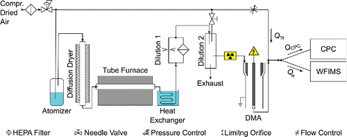
The WFIMS was characterized using monodisperse ammonium sulfate (NH4)2SO4 particles classified by a cylindrical DMA (TSI Inc., Shoreview, MN, USA, Model 3081/3085). WFIMS has a measurement size range of 8 to 580 nm (), however we focused the experimental characterization on smaller sizes from 8 to 265 nm, because the size dependence of particle detection efficiency and the impact of Brownian diffusion on the instrument's resolution are more pronounced at small sizes. A schematic diagram of the experimental setup is shown in . Particles ranging from 8 nm to 100 nm in diameter were generated by atomizing a dilute (NH4)2SO4 solution (0.75 mM) using a constant output atomizer (TSI Inc., Model 3076), followed by a diffusion dryer, a tube furnace operated at a temperature of 230°C, and a heat exchanger. Larger particles with diameters ranging from 100 to 265 nm were generated by atomizing a dilute (NH4)2SO4 solution (7.6 mM) followed by diffusion drying only. To achieve stable particle number concentrations ranging from 1 to 100 cm−3, the dilution of the output aerosol was optimized by adapting (Equation1[1] ) the diameter of a limiting orifice in dilution stage 1 and/or (Equation2
[2] ) the dilution flow via a needle valve (dilution stage 2). The diluted polydisperse particles were introduced into a 85Kr bipolar aerosol neutralizer (TSI Inc., Model 3077) and subsequently classified in a DMA to obtain monodispersed particles. Particles smaller or equal to 50 nm were classified with a nano-DMA (TSI Inc., Model 3085), above 50 nm a long-column DMA (TSI Inc., Model 3081) was used. The ratio of DMA aerosol to sheath and sample to excess flow was kept constant at 1:10, while DMA sheath flow was switched between 8 l/min and 14.2 l/min to optimize the size range of classified particles and the resolution of the DMA. To maintain constant WFIMS and CPC (TSI Inc., Model 3010) inlet flows, Qa and QCPC, respectively, a variable particle-free makeup flow, QTr, was mixed with the monodispersed aerosol flow exiting the DMA before introduced to WFIMS and CPC. Note to avoid any potential uncertainties introduced by particle charging efficiency, we removed the aerosol neutralizer from WFIMS inlet in this study. The temperature difference between CPC condenser and saturator was increased to 21°C to increase the counting efficiency below 20 nm (Mertes et al. Citation1995). Size-dependent CPC counting efficiencies ηCPC of positively charged ammonium sulfate particles at a CPC sample flow rate of 1.1 l/min were determined using an electrometer (TSI Inc., Model 3068B) as reference. The calibration yielded a CPC cutoff diameter, Dp,50, of 8 nm in agreement with the data presented in Mertes et al. (Citation1995).
WFIMS aerosol and total flow, Qa and Qtot, were maintained at 0.3 l/min and 16.5 l/min, respectively. Differences between growth channel temperatures and the separator temperature (∼25°C), ΔTcon, ΔTini, and ΔTmod were kept at −12°C, +28°C, and −10°C, respectively. Minimum and maximum voltages V1 and V2 applied across the HV electrode were set to 20 V and 6000 V, respectively. Before starting each experiment, the aerosol generation system was allowed to stabilize and flows were calibrated with a flow calibrator (Gilian Intruments, Columbus, OH, USA, Gilibrator).
5. Results and discussion
The performance of the WFIMS, as characterized by its sizing accuracy, detection efficiency, and mobility resolution was evaluated using the experimental setup described above.
5.1. Size measurement with DMA classified aerosol
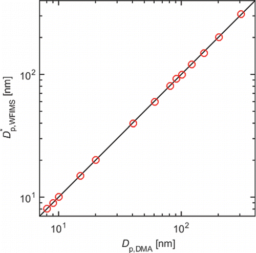
The sizing accuracy of WFIMS was assessed by comparing mean diameters measured by WFIMS with DMA centroid diameters for particles ranging from 8 to 265 nm. For each selected particle size, CCD images were acquired over a period Δt of 10 min.
shows the instrument response diameter , which is derived from instrument response mobility Zp* measured by WFIMS assuming singly charged particles. As can be seen from this graph, DMA and WFIMS diameters are in good agreement indicating a high sizing accuracy of the latter. For the entire size range, i.e., 8–265 nm, the maximum deviation between
and Dp,DMA never exceeded 2%.
5.2. Counting efficiency
Particle size and concentration-dependent WFIMS counting efficiency η, i.e., the fraction of the particles within the viewing window that are detected by WFIMS, was evaluated by comparing total particle number concentrations measured by the WFIMS, i.e., NWFIMS, to those measured by a CPC using[1] with ηCPC being the CPC counting efficiency and
being
[2] where nΔt is the total number of particles counted within the viewing window during measurement period Δt and Qa is the aerosol sample flow rate.
In general, the counting efficiency η of a particle counter is given by[3] where ηpen, ηtrans, and ηdet are penetration, transmission, and detection efficiency, respectively. In the case of WFIMS, the penetration efficiency ηpen describes particle losses along the inlet line, i.e., the flow passage between instrument inlet and mobility separator. WFIMS' transmission efficiency ηtrans(Dp) gives the fraction of particles entering the mobility separator that exit the growth channel within the viewing window. As the viewing window spans 7 cm in the center of channel cross-section, only a fraction of particles introduced through the inlet slit, which spans the entire channel width of 12.7 cm, may be detected within the viewing window. This is accounted for in the transmission efficiency. Finally, the detection efficiency ηdet represents the fraction of particles exiting the growth channel within the viewing window that are detected by the CCD camera. Since the major modification to the heptanol-based FIMS with enhanced dynamic size range (Wang et al. Citation2017a,Citationb) is the replacement of the condenser with a three-stage water growth channel, following discussion will focus on ηdet. A detailed description of penetration and transmission efficiencies is given in the SI S.3.
The detection efficiency ηdet is given by[4]
ηdet mainly depends on whether particles grow to sufficient sizes to be detected optically, which is controlled by particle diameter and the local saturation ratio along the particle trajectories in the growth channel. Particle transport and growth inside the growth channel was simulated in a two-step process to estimate the lower size limit of WFIMS. First, the finite element modeling software package COMSOL Multiphysics® was used to determine the flow profile, temperature, and vapor concentration. The model also included the thermal conductivity of the wicks and the heat source/sink from condensation/evaporation at the surface. Then we used MATLAB to integrate the droplet growth along its trajectory in the supersaturated flow (Lewis and Hering Citation2013). The particle Brownian motion before activation inside the growth channel was neglected, and the trajectory of the particles was assumed to follow flow streamlines. From modeled water vapor saturation ratios and equilibrium Kelvin diameters inside the growth channel (), it can be concluded that particles as small as 5.5 nm can be activated and grow large enough (>1 μm) to be detected optically. In other words, no size dependence is expected for ηdet.
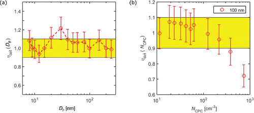
As shown in , WFIMS' detection efficiency is essentially 100% for particles ranging from 8 to 265 nm in agreement with modeled water vapor saturation ratio and droplet growth described above. Deviations from unity, observed in both directions, are mostly within 10%, and could be due to the uncertainty in WFIMS and CPC measurements, at least partially. This also suggests that calculated transmission and penetration efficiencies capture actual particle losses and transport sufficiently well (Equation (Equation4[4] )). The data shown in were measured at NCPC ≤ 100 cm−3. When the particle number concentration at a single particle size is significantly higher, optical coincidences can lead to an underestimation of measured particle number concentrations. This measurement artifact is shown in , where ηdet is plotted as a function of NCPC for DMA classified 100 nm ammonium sulfate particles. ηdet decreases substantially as the number concentration of size-selected particles exceeds about 130 cm−3, and at the concentration of 800 cm−3, coincidence leads to a 30% underestimate of the concentration measured by the WFIMS. A way to correct for optical coincidences is shown in the SI Section S.4. However, for the measurements of ambient aerosol particles, the upper concentration limit is much higher because WFIMS only measures charged particles and a fraction of the particles is lost during transport in the inlet line, especially for smaller particles. In addition, atmospheric aerosols are polydisperse. As a result, detected particles spread across the entire imaging window instead of a narrow “arc,” leading to negligible impact from coincidence at much higher total particle number concentrations. As shown in the SI Section S.5, the impact of coincidence remains very minor (<1%) until the particle number size distribution exceeds those under typical polluted conditions by at least one order of magnitude, when particle charging efficiency and penetration efficiency are taken into consideration. Thus, we expect that the impact of optical coincidence is largely negligible for measurements of ambient aerosol populations. It should be noted that it would be possible to increase the CCD frame rate from 10 to 60 Hz and thereby increase the upper concentration limit by a factor of about 6 if necessary, e.g., when sampling highly concentrated aerosol.
Figure 7. WFIMS detection efficiency ηdet as function of (a) particle diameter Dp for particle concentration NCPC < 100 cm−3 and (b) particle number concentration NCPC for particle diameter Dp = 100 nm. The area highlighted in yellow represents the ±10% uncertainty interval typical for particle counters.
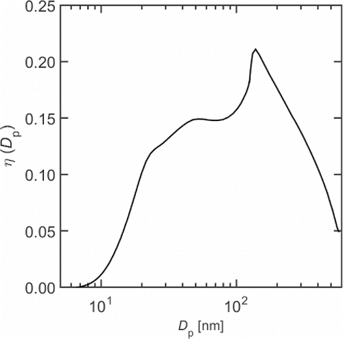
Given the essentially 100% detection efficiency, WFIMS' counting efficiency η can be reduced to the product of penetration and transmission efficiency. The resulting size-dependent counting efficiency shown in exceeds 10% between 20 nm and 400 nm, exhibits a global maximum of about 21% at 140 nm, and decreases to 1% and 5% at 10 nm and 580 nm, respectively. The non-monotonic behavior of η(Dp) can be attributed to the shape of ηtrans(Dp) (see the SI Section S.3). A detailed analysis of WFIMS counting statistics shows that for typical remote continental aerosol (Jaenicke Citation1993), the relative uncertainty of 1 s WFIMS size distribution measurements is less than 30% for particles with diameters between 15 nm and 280 nm, a size range that dominates the overall particle number concentration (see the SI Section S.5). The uncertainties in total number concentration and mean particle diameter derived from 1 s measurements are about 6%.
5.3. Mobility resolution
In addition to sizing accuracy and counting efficiency, mobility resolution of the WFIMS is evaluated by comparing its calculated and measured response to DMA classified particles (Dp,DMA = 8 to 265 nm). As an analytic form of WFIMS transfer function is not available, it is very challenging to characterize the WFIMS transfer function experimentally through fitting a few controlling parameters as was done in Kulkarni and Wang (Citation2006b). Here, we examine the WFIMS mobility resolution by comparing the shape of measured/simulated response mobility distribution , where Zp,DMA and Zp* are DMA centroid diameter and WFIMS instrument response mobility, respectively. To facilitate the comparison, overall mobility resolutions
and
are introduced. Note due to the unique shape of WFIMS' transfer function (Wang Citation2009; Wang et al. Citation2017a)
, the resolution based on FWHM, might fail to capture the overall spread of
unlike
, the resolution based on the standard deviation of
. A detailed derivation of
and
can be found in the SI Section S.6. In the following discussions, subscripts “std” and “FWHM” are omitted unless a clear distinction between RFWHM and Rstd is necessary.
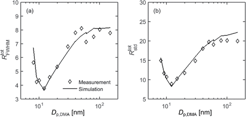
As shown in , measured (open [red] diamonds) and simulated (dash-dotted [red] lines) overall mobility resolutions are in fairly good agreement. For DMA centroid diameters Dp,DMA below 60 nm, the mean deviation is about 6%. Between 60 and 250 nm, simulated Rtot exceed measured ones by 15% on average. The cause of the discrepancy between 60 and 250 nm is studied by examining for particles detected in different sub-areas of the viewing window following the approach described in Wang et al. (Citation2017b).
Figure 9. Measured (open [red] diamonds) and simulated (dash-dotted [red] lines) overall mobility resolutions (a) and (b)
as a function of DMA centroid diameter Dp,DMA. Solid and dashed [black] lines indicate simulated WFIMS and DMA instrument mobility resolutions RWFIMS and RDMA, respectively.
![Figure 9. Measured (open [red] diamonds) and simulated (dash-dotted [red] lines) overall mobility resolutions (a) and (b) as a function of DMA centroid diameter Dp,DMA. Solid and dashed [black] lines indicate simulated WFIMS and DMA instrument mobility resolutions RWFIMS and RDMA, respectively.](/cms/asset/5add0cbe-7332-4a59-bbf1-7284b2cb8404/uast_a_1338664_f0009_oc.gif)
illustrates averaged measured (dash-dotted [red]) and simulated (solid [green]) particle positions at the growth channel exit for DMA classified ammonium sulfate particles (Dp,DMA = 60 nm). The dash-dotted [red] arc is rotated clockwise with respect to the green arc, which suggests that, for the same monodispersed aerosol, on average particles detected closer to the ground electrode (x/a = 0) were measured with a higher instrument response mobility Zp* than those detected near the HV electrode (x/a = 1). This shift in measured Zp* is further illustrated in using normalized for different sub-areas of the viewing window. Dashed [blue], solid [green], and dotted [black] lines correspond to detected particle x-positions xf ranging from 0.2·a to 0.3·a, 0.45·a to 0.55·a, and 0.7·a to 0.8·a, respectively. Clearly measured Ptot moves toward larger Zp* with increasing xf limits. This results in a broader Ptot for the entire viewing window (dash-dotted [red] line) and hence lower mobility resolution Rtot than simulated (subplot (c)). The shift in measured Ptot toward larger Zp* with increasing xf limits is likely due to non-idealities of the electric field, which are not represented by the simplified 2-D electric field used to simulate particle trajectories.
Figure 10. (a) CCD image showing averaged simulated (solid [green] line) and measured (dash-dotted [red] line) positions of 60 nm ammonium sulfate particles at the separator exit. Corresponding normalized distributions Ptot derived from measured and simulated particle positions are illustrated in subplot (b) and (c), respectively. Line colors represent different viewing window sub-areas.
![Figure 10. (a) CCD image showing averaged simulated (solid [green] line) and measured (dash-dotted [red] line) positions of 60 nm ammonium sulfate particles at the separator exit. Corresponding normalized distributions Ptot derived from measured and simulated particle positions are illustrated in subplot (b) and (c), respectively. Line colors represent different viewing window sub-areas.](/cms/asset/dcac9067-e947-4bbe-a96c-a6610f1ede86/uast_a_1338664_f0010_oc.gif)
Better agreement between measured and simulated instrument resolution is found for narrower xf ranges. This is demonstrated in , where Rtot for particles detected within 0.45·a–0.55·a is plotted as a function of Dp,DMA. Note the narrower xf range reduces the upper detectable size limit to 150 nm. Now measured Rtot, particularly , largely agree with simulations, while some minor discrepancies remain for particles larger than 40 nm. As the overall spread of
is dominated by the width of DMA transfer function for particles larger than 40 nm (), these minor discrepancies may be due to slightly degraded DMA resolution as reported in some of the earlier studies (Zhang and Flagan Citation1996). They attributed the degradation in the resolution of the cylindrical DMA and radial DMA partially to flow disturbance in the aerosol entrance slit. Similar flow disturbance near WFIMS aerosol inlet may lead to reduced Rtot, however, this impact seems to be minor given the better agreement in measured and calculated overall mobility resolutions for particles with diameters less than 40 nm. The better agreement between the size-dependent Rtot for particles detected within sub-areas of the viewing window indicates that the Zp* shift in measured
with varying xf range is most likely the main cause for the discrepancy between measured and simulated overall mobility resolution corresponding to the entire viewing window for particles larger than 40 nm.
6. Conclusions
We present a water-based fast integrated mobility spectrometer (WFIMS) with enhanced dynamic size range. The measuring principle is based on the fast integrated mobility spectrometer (Kulkarni and Wang Citation2006a,b) with extended size range (Wang et al. Citation2009, Citation2017a,b) and laminar flow water-based condensation methodology (Hering and Stolzenburg Citation2005). The WFIMS uses a drift channel to separate particles of differing electrical mobility. Subsequently, the spatially separated particles are enlarged through water condensation along their flow trajectories, and their positions within the channel are captured via digital imaging. The growth channel is designed to use a “moderator” stage (Hering et al. Citation2014) to remove excess water vapor so as to provide the necessary condensational enlargement without risking condensation on the downstream optical components. Rather than sampling one size fraction at a time, as done with traditional mobility sizing systems, particles of different mobilities are detected simultaneously, with a data acquisition rate of 10 Hz.
WFIMS measures particles ranging from 8 to 580 nm in a single snapshot. However, we focused its performance characterization on DMA classified ammonium sulfate particles ranging from 8 to 265 nm in diameter, where the size dependence of detection efficiency and the impact of Brownian diffusion on transfer function were expected to be more pronounced. DMA centroid diameters agree well with particle sizes measured by WFIMS, indicating high sizing accuracy of the latter. Counting statistics analysis shows that the detection efficiency is nearly 100% for particles with diameters from 8 nm upward. This is consistent with modeled saturation ratio profiles and droplet growth inside the growth channel. The WFIMS mobility resolutions are examined experimentally by studying the response of WFIMS to DMA classified monodispersed particles. The results indicate that for particles with diameters less than 40 nm, the WFIMS resolutions are well represented by the calculated resolutions based on simulated particle trajectories. For particles larger than 40 nm in diameter, degradation of WFIMS resolution is observed, and is likely due to non-idealities of the electric field, which yield variation in measured response mobility for particles detected with different x positions.
UAST_1338664_Supplemental_File.zip
Download Zip (1.3 MB)Acknowledgments
The authors thank Andrew McMahon, Scott Smith, and Thomas Tsang for their help with the development of WFIMS.
Funding
This work was supported by the U.S. Department of Energy's Small Business Innovation Research Program under contract DE-SC0013103, Small Business Technology Transfer Program under contract DE-SC0006312, and Atmospheric System Research Program (Office of Science, OBER) under contract DE-AC02-98CH10886.
References
- Baker, R. W. (2012). Membrane Technology and Applications. Wiley, New York.
- Biskos, G., Reavell, K., and Collings, N. (2005). Description and Theoretical Analysis of a Differential Mobility Spectrometer. Aerosol Sci. Technol., 39(6):527–541.
- Flagan, R. C. (1999). On Differential Mobility Analyzer Resolution. Aerosol Sci. Technol., 30(6):556–570.
- Hering, S. V., Spielman, S. R., and Lewis, G. S. (2014). Moderated Water Based Condensational Particle Growth in a Laminar Flow. Aerosol Sci. Technol., 48(4):401–408.
- Hering, S. V., and Stolzenburg, M. R. (2005). A Method for Particle Size Amplification by Water Condensation in a Laminar Thermally Diffusive Flow. Aerosol Sci. Technol., 39(5):428–436.
- Hering, S. V., Stolzenburg, M. R., Quant, F. R., Oberreit, D. R., and Keady, P. B. (2005). A Laminar Flow Water Based Condensation Particle Counter WCPC. Aerosol Sci. Technol., 39(7):659–672.
- Jaenicke, R. (1993). Tropospheric Aerosols. Int. Geophys., 54:1–31.
- Johnson, T., Caldow, R., Pöcher, A., Mirme, A., and Kittelson, D. (2004). A New Electrical Mobility Particle Sizer Spectrometer for Engine Exhaust Particle Measurements. SAE 2004 World Congress & Exhibition 2004-01–134.
- Kulkarni, P., and Wang, J. (2006a). New Fast Integrated Mobility Spectrometer for Real-Time Measurement of Aerosol Size distribution—I: Concept and Theory. J. Aerosol Sci., 37:1303–1325.
- Kulkarni, P., and Wang, J. (2006b). New Fast Integrated Mobility Spectrometer for Real-Time Measurement of Aerosol Size Distribution: II. Design, Calibration, and Performance Characterization. J. Aerosol Sci., 37:1326–1339.
- Lewis, G. S., and Hering, S. V. (2013). Minimizing Concentration Effects in Water-Based, Laminar-Flow Condensation Particle Counters. Aerosol Sci. Technol., 47(6):645–654.
- Mertes, S., Schröder, F., and Wiedensohler, A. (1995). The Particle Detection Efficiency Curve of the TSI 3010 CPC as a Function of the Temperature Difference between Saturator and Condenser. Aerosol Sci. Technol., 23(2):257–261.
- Mirme, A. (1994). Electrical Aerosol Spectrometry. UniversitatisTartuensis, Tartu, Estonia.
- Mirme, A., Noppel, M., Peil, I., Salm, J., Tamm, E. and Tammet, H. (1984). Multi-Channel Electric Aerosol Spectrometer, in 11th International Conference on Atmospheric Aerosols, Condensation and Ice Nuclei, Budapest, Hungary. pp. 155–159.
- Pinterich, T., Spielman, S. R., Hering, S. V., and Wang, J. (2017). A Humidity-Controlled Fast Integrated Mobility Spectrometer (HFIMS) for Rapid Measurements of Particle Hygroscopic Growth. Submitted to Atmospheric Measurement Techniques.
- Spielman, S. R., Hering, S. V., Kuang, C., and Wang, J. (2017). Preliminary Investigation of a Water-Based Method for Fast Integrating Mobility Spectrometry. Aerosol Sci. Technol., DOI: 10.1080/02786826.2017.1338338
- Tammet, H., Mirme, A., and Tamm, E. (1998). Electrical Aerosol Spectrometer of Tartu University. J. Aerosol Sci., 29:S427–S428.
- Tammet, H., Mirme, A., and Tamm, E. (2002). Electrical Aerosol Spectrometer of Tartu University. Atmos. Res., 62:315–324.
- Wang, J. (2009). A Fast Integrated Mobility Spectrometer with Wide Dynamic Size Range: Theoretical Analysis and Numerical Simulation. J. Aerosol Sci. 40:890–906.
- Wang, J., McNeill, V. F., Collins, D. R., and Flagan, R. C. (2002). Fast Mixing Condensation Nucleus Counter: Application to Rapid Scanning Differential Mobility Analyzer Measurements. Aerosol Sci. Technol., 36:678–689.
- Wang, J., Pikridas, M., Pinterich, T., et al. (2017b). A Fast Integrated Mobility Spectrometer with Enhanced Dynamic Size Range, Part II: Experimental Characterization. J. Aerosol Sci., DOI: 10.1016/j.jaerosci.2017.05.001
- Wang, J., Pikridas, M., Spielman, S., and Pinterich, T. (2017a). A Fast Integrated Mobility Spectrometer with Enhanced Dynamic Size Range, Part I: Design and Model Evaluation. Atmos. Meas. Tech., 108:44–55.
- Winkler, P. M., Ortega, J., Karl, T., McMurry, P. H., and Smith, J. N. (2013). A Fast-Scanning DMA Train for Precision Quantification of Early Nanoparticle Growth. AIP Conf. Proceed., 1527:165–168.
- Zhang, S., and Flagan, R. C. (1996). Resolution of the Radial Differential Mobility Analyzer for Ultrafine Particles. J. Aerosol. Sci., 27:1179–1200.

