ABSTRACT
Particle emissions from multiple fused deposition modeling consumer 3D printers were systematically quantified utilizing an established emission testing protocol (Blue Angel) to allow quantitative exposure assessments for printers operating in different environments. The data are consistent with particle generation from volatilization of the polymer filament as it is heated by the extruder. Typically, as printing begins, a burst of new particle formation leads to the smallest sizes and maximum number concentrations produced throughout the print job. For acrylonitrile butadiene styrene (ABS) filaments, instantaneous concentrations were up to 106 #/cm3 with mean particle sizes of 20 to 40 nm when measured in a well mixed 1 m3 chamber with 1 air change per hour. Particles are continuously formed during printing and the size distribution evolves consistent with vapor condensation and particle coagulation. Particles emitted per mass of filament consumed (particle yield) varied widely due to factors including printer brand, and type and brand of filament. Higher extruder temperatures result in larger emissions. For filament materials tested, average particle number yields ranged from 7.3 × 10⁸ to 5.2 × 10¹⁰ g−1 (approximately 0.65 to 24 ppm), with trace additives apparently driving the large variations. Nanoparticles (diameters less than 100 nm) dominate number distributions, whereas diameters in the range of 200 to 500 nm contribute most to estimated mass. Because 3D printers are often used in public spaces and personal residences, the general public and particularly susceptible populations, such as children, can be exposed to high concentrations of non-engineered nanoparticles of potential toxicity.
Copyright © 2017 American Association for Aerosol Research
EDITOR:
1. Introduction
The 3D printer market is estimated to have a compounded annual growth rate of 44% (Alto Citation2015). Among diverse 3D printers on the market, fused deposition modeling (FDM) printers, which heat a filament to semi-liquid state and deposit it to build a 3-dimensional object by layers (Zukas and Zukas Citation2015) are relatively inexpensive and convenient to use, making them accessible to the general public. The most commonly used filament materials are thermoplastics like acrylonitrile butadiene styrene (ABS) and polylactic acid (PLA) (Ragan Citation2013). Other types are continuingly becoming available, including polyamide (nylon) and polyethylene terephthalate (PET) (MatterHackers Citation2015). Desktop sized 3D printers in particular, are often used in educational institutions, public spaces such as libraries, design offices and within homes (Harrop Citation2015). It is known that the commercial extrusion processing of thermoplastics emits both particles and volatile organic compounds (VOCs) (Adams et al. Citation1999), and some of the thermal decomposition products are recognized to be toxic (Rutkowski and Levin Citation1986; Unwin et al. Citation2013; Yoon et al. Citation2010). It follows that FDM 3D printers are potentially hazardous to operate in certain indoor environments. Due to the increasing usage of 3D printers, and past experience with laser printer emissions, characterization of 3D printer emissions is necessary to assess human exposure and potential health impacts.
A number of studies have investigated particle emissions from consumer FDM 3D printers using multiple filament materials. All show significant emissions of approximate same order of magnitude to other indoor sources, such as laser printers and some cooking processes. A detailed review of nine previous studies is provided in the online supplementary information (SI) including a summary on their conditions and results (Table S1).
Although there is some consistency between studies, comparing particle emissions reported, and factors associated with these emissions, is difficult because no standard testing protocol has been utilized. For example, different testing environments were used, including chambers versus actual workspaces of different dimensions and air supply rates, resulting in different air exchange rates (ACH) and degrees of mixing, all of which can have an effect on the measured emissions. Furthermore, different emission analysis methods have been employed, such as assuming a steady state mass balance, a dynamic mass balance or utilizing a simple box model. Some considered particle losses to surfaces (chamber walls), while others did not. Differing parameters were also used to summarize emissions, such as average or median particle emission rates, which depended on calculation methods and were normalized to print time, mass or length of filament used, and peak or average particle concentrations. Finally, differences in monitoring instrumentation can also limit comparisons since particle size ranges measured also varied. Though all studies show emissions of non-engineered nanoparticles from consumer FDM 3D printers, a standard testing and evaluating method is essential to understand how printer operation variables drive particle emission and evolution, and to quantitatively compare results between investigators. In this study, we follow the established test protocol developed for characterizing laser printer emissions (BAM Citation2012), which also allows direct comparison of consumer 3D printer emissions to those of laser printers. Using this method, printer operating conditions, including printer brand, filament type, brand and color, extruder and build plate temperature, were tested in a systematic manner.
2. Materials and methods
2.1. Printers and materials tested
Six commercially popular FDM 3D printer brands were tested, referred to as A through F; their differing properties, including extruder temperature, build plate and configuration design, are listed in . Three kinds of widely used filament materials were tested: ABS, PLA and nylon, all with a diameter of 1.75 mm. Filament material densities were taken to be 1.07 g/cm3 for ABS, 1.22 g/cm3 for PLA and 1.13 g/cm3 for nylon, according to manufacturer Material Safety Data Sheets. Filaments were acquired from differing manufacturers (i.e., sellers) since subtle differences in minor constituents or additives that can vary by manufacturers, but go unreported, may have large effect on emissions. Filament brands are referred to as a through j. In order to assess the influence of printing conditions on emission, experiments were designed to vary one variable at a time and mainly done on printer A, B, C with filament brand a through e, which led to 52 combinations of printer brand, filament material, filament brand, filament color and extruder temperature; the rest of the printers and filaments tested were included when comparing overall emissions. Additionally, a set of different objects was printed, resulting in various print times due to differing object size and shape, filament feed rate and object support setting. Details of all printing combinations tested are shown in Table S2.
Table 1. Specifications of printers tested in this study.
2.2. Environmental chamber
A 1 m3 environmental chamber (1 × 1 × 1 m) of polished stainless steel interior and thermally insulated walls was used in all experiments; it is designed and evaluated following ASTM standard D6670 guidance (ASTM Citation2013), UL GREENGUARD Certification (UL Citation2014) and ECMA-328 (ECMA Citation2015). It is utilized to determine emissions from laser printers following the Blue Angel Method (BAM Citation2012), which was developed to test the emissions from office equipment with printing functions. Airflow entered and exited the chamber through two stainless steel air distribution manifolds, aerodynamically designed to provide well-mixed conditions inside the chamber. A clean air supply system delivered 16.7 L/min of dried room air free of VOCs and particles via a gas absorption tower and a HEPA filter, resulting in an ACH of 1 hr−1, as recommended in the Blue Angel Method (2012). The temperature and relative humidity (RH) inside the chamber were continuously monitored; all experiments were done under dry conditions (RH = 3.0% ± 0.2%) and at near room temperatures (23 ± 1°C). During experiments, the printer was placed in the middle of the chamber; particle and VOC sampling tubes were connected through sealable sampling ports on the walls and the ceiling of the chamber that extended approximately 10 cm away from the chamber walls and 10–20 cm from the printer. (VOC results are not presented in this article.) All particle sampling lines were conductive (stainless steel or conductive silicon) to minimize electrostatic particle losses. Power and printer control wires were also passed through sealed ports.
2.3. Particle measurement instrumentation
Particles were measured online using three instruments. A condensation particle counter (CPC, TSI, Shoreview, MN, USA) measured total number of particles with diameter larger than nominally 7 nm to larger than 3 µm; a scanning mobility particle sizer (SMPS, TSI) spectrometer measured number distributions for particle electrical mobility diameter between 7 and 300 nm and an optical particle counter (OPC, TSI) measured particle number distributions for particle optical diameter of 300 nm to 25 µm. Instrument specifications are shown in Table S3. Factory calibrations for inferring particle size from light scattering are used for the OPC. Particle surface area and volume concentrations were calculated from the measured number distributions assuming spherical particles, and mass estimated using the densities of bulk filament materials. Consistency between the CPCs was tested on 3D-printer generated particles prior to the printing experiments, see SI Section S4 and Figure S1. It is noted that both the inferences of particle size by the SMPS and OPC, and the conversion of number distributions to surface area and mass distributions rely on assuming the particles are spherical. Imaging of 3D printer particles, however, showed this is not the case (Zontek et al. Citation2017; Steinle Citation2016). The spherical particle assumption will lead to uncertainties in our analysis, we estimated the particle diameter determined from the SMPS may be biased high by at most 20%, surface area biased low by 30% and mass biased high by 40%. (See SI Section S5.1.)
2.4. Test protocol
Tests were carried out following the procedures described in BAM (Citation2012). Before every experiment, the printer to be tested was prepared inside the chamber and then the chamber continuously flushed with clean air to achieve a background total particle concentration below 5 cm−3 (CPC) and total mass concentration below 1 μg/m3 (SMPS and OPC). To begin the test, particle measurements were started at least 15 min before print started. Before extrusion, a few minutes were required for the printers to initiate (transfer file, find position and heat extruder and build plate if needed), which varied for different printers. Few particles were generated during this process. The printing period discussed hereafter is the time between when extrusion started and then stopped. The particle measurements continued after the print had stopped for at least 2-h, or until concentrations returned to near-background level so that wall losses could be inferred.
2.5. Data analysis methods
The data analysis methods follow BAM (Citation2012) based on the sections discussing fine and ultrafine (nanoparticle) particle measurements in emission test chambers. All calculation methods were applied in the same way for particle number, surface area and mass concentrations. This provides a proven and standardized method for analyzing and reporting emissions, consistent with those used for laser printer emissions (Koivisto et al. Citation2010; Schripp et al. Citation2008; Salthammer et al. Citation2012). Particle emission rates (PERs) as a function of print time and total particle (TP) emissions from the complete print job were calculated, considering particle losses to surfaces. Details of the calculation methods are provided in the SI (Section S5), along with the statistical methods used to examine the quality of experimental data and to interpret the results.
In addition to these variables, particle yield was developed specifically for 3D printers to evaluate the particle emissions from a specific printer and filament combination. It is defined as the TPs emitted for a given print job, divided by the printed object mass, including object supports (i.e., the mass of filament used for the complete print job). This definition was applied to particle number, surface area and mass emissions.
3. Results and discussions
3.1. Particle concentration and size distribution time series and aerosol dynamic processes
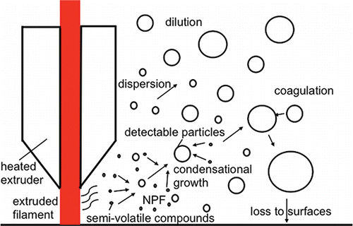
In the following analysis we interpret the evolution of the aerosols measured in the chamber as a function of time in terms of known processes expected to be occurring (). Aerosol dynamic model simulations are needed to actually quantify these processes, but beyond the scope of this article.
Figure 1. Schematic of particle formation, growth, and loss processes. NPF is new particle formation resulting from nucleation of emitted semi-volatile vapors.
3.1.1. Particle number concentrations
A common feature of 3D printer particle emission profiles is a large jump in number concentrations at the start of the print job, which are typically the maximum number concentrations observed over the entire printing process (Azimi et al. Citation2016; Kim et al. Citation2015; Steinle Citation2016; Yi et al. Citation2016). This is consistent with new particles generated in the vicinity of the extrusion nozzle due to high concentrations of semi-volatile compounds (SVCs) emitted from the heated filament, which may include semi-volatile organic compounds and other species associated with the bulk filament or additives. Since the concentration of pre-existing particles at the beginning of the process is low (i.e., background room or chamber concentrations) relative to after the printer has been in operation for a period of time, loss of the SVCs by condensation onto pre-existing particles will be low and so these vapor concentrations increase to a point where new particle formation (NPF) can occur at substantial rates (). Once formed, these particles rapidly grow and reach detectable sizes (Dp > 7 nm). We have confirmed that this occurred when the printer was operated with ABS with particle-free air introduced into the chamber, or when typical room-air background levels are present at the beginning of the print job (Figure S2).
and show typical print runs using ABS filament for two print job times. Almost immediately once extrusion started, the total particle number concentration and the concentration for 7–50 nm particles reach a maximum of about 3.4 × 10⁵ #/cm3 ( and ). As more particles are formed and grow, their surfaces can provide an increasing sink for SVCs, lowering the vapor concentrations. This is expected to happen fairly rapidly, (e.g., ∼5 min following the start of extrusion, based on the data) and likely leads to a reduction in NPF, observed as a drop from the initial peak concentrations for the smallest measured particles (). As semi-volatile vapors continued to be emitted during printing, NPF is expected to still occur, but at a reduced level since vapors are continuously being scavenged through condensation. Note that not all printers have the same temporal trend as shown in . An example of a different time series trend for ABS observed can be found in Figure S4. The causes of more random concentration variations over the print period are not fully known, but appear to be related to the design of the printer (e.g., open versus closed, etc.).
Figure 2. Time series of particle number concentrations averaged over various particle size ranges on log scale (a), total particle concentrations on linear scale (b), evolution of size distributions (c) and average particle number distributions during the printing period separated into 5 time intervals (d). The print condition was ABS filament brand a, red color on printer A; the printing period was 47 min, identified by the vertical lines.
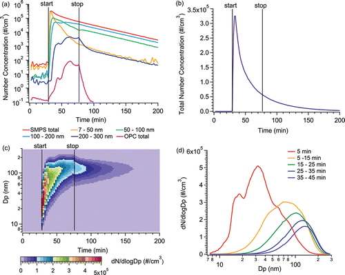
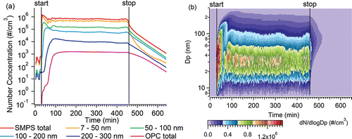
Figure 3. Long time print job time series of particle number concentrations (a) and size distributions (b) for ABS filament brand d green color on printer A; the printing period was 7 h 4 min, identified by the vertical lines.
Ultrafine or nanoparticles (Dp < 100 nm) dominate the number distributions (90%), but their concentrations decrease rapidly during the printing period, especially for 7–50 nm particles, whereas larger particles (Dp > 100 nm) gradually increase in concentration (). Semi-volatile compounds are expected to be continuously generated from the heated filament at the extruder nozzle or recently deposited filament as printing proceeds, and the new sub-50 nm particles formed at the beginning continue to grow by vapor condensation. A delay is observed in the appearance of larger particles due to the time needed for particle growth ( and ). In addition, as number concentrations and particle sizes increase, particle coagulation is expected to become more prevalent. This is also seen in the size distributions in and , where the particle number distributions shift to larger size over time, and the shape of the size distribution in resembles the classic banana shape of nucleation-growth-coagulation seen in the ambient atmosphere (Curtius Citation2006).
While particle formation and growth processes are occurring, due to dilution by continuous clean air exchange, the particles are dispersing as air parcels move away from the extruder; in addition to losses of some fraction of particles to the printer surfaces and the chamber walls, a decay in concentrations in the overall chamber is observed. When the printing job ends, with no source of condensable-vapors, these processes are especially evident as an exponential decay in concentrations toward background levels present before the print started ( and ).
For shorter print jobs (), these aerosol dynamic processes may never reach steady state before printing ends, whereas for longer jobs (), concentrations of various sizes can remain relatively constant after about 1 h of printing (for this condition), indicating the processes of particle formation, vapor-condensational growth, coagulation and loss reach a steady state. Maximum particle concentrations and the steady state concentrations vary from case to case. Furthermore, the ACH of the testing environment, or forced air cooling by the nozzle, can affect the particle dynamics as the vapors and newly formed particles move away from the extruder nozzle region, changing the relative rates of NPF, condensation, coagulation and loss, in turn affecting particle final sizes and number concentrations.
Most PLA filament runs showed similar concentration profiles as in ; however, the steady state condition (e.g., ) was seldom observed, probably because PLA emitted less SVCs, resulting in lower NPF and growth rates. Thus fewer particles accumulate in a continuously diluting environment and particle concentrations gradually decrease. For some PLA cases, the maximum particle number concentrations were not observed at the beginning of the print, but 10 to 60 min after print started. The difference is likely due to the amount of SVCs emitted near the extruder nozzle and newly-deposited filament (note, emissions from the heated build plate will be discussed below). With much lower condensable SVC concentrations emitted from PLA, it takes longer for the NPF and growth processes to occur and longer times for particles to accumulate. Example time series plots for PLA are shown in Figure S5 and S6.
Pre-existing room air particles have an effect on PLA aerosol production. When there was a relatively high initial background concentration (∼104 #/cm3), the pre-existing particles provided enough surfaces for vapors to condense on, instead of forming new particles. This led to no increase in number concentrations observed throughout the print job, but an increase in mass concentrations (Figure S3).
3.1.2. Particle surface area and mass concentrations
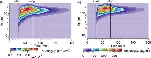
Evolution of the particle surface area and mass concentration distributions for the shorter print run in are shown in . (Plots of surface area and mass concentration time series and size distributions with more details are in Figures S7 and S8). Compared to number concentration profiles, the surface area and mass concentrations both take longer to reach a maximum. The large number of newly formed particles contributes little to surface area or mass, but as printing continues to supply vapors, particle growth by condensation of vapors leads to a rise in surface area and mass concentrations (note, this also corresponds to a loss in the smallest particle numbers in ). Near the beginning of the print, nanoparticles (Dp < 100 nm) contributed less than 50% to the total surface area and mass concentrations, and decreased quickly. Instead, 100 – 200 nm particles dominated the surface area concentrations, while for mass slightly larger (Dp ∼ 200 nm); particles larger than 300 nm (OPC data) contributed less than 1% to overall surface area and mass due to their low concentrations in this case (Figure S7). For longer print times (Figure S8), larger particles (Dp > 300 nm, OPC data) contribute more to the overall surface area and mass of emitted particles (∼6% for surface and ∼23% for mass), since there is sufficient time for the particles to substantially grow.
Figure 4. Evolution of particle surface area (a) and mass (b) distributions, calculated from number distributions shown in , assuming spherical particles and a density of 1.07 g/cm3 (bulk ABS).
It is noteworthy that number distributions have a very different behavior compared to surface area and mass. These differences matter depending on how particle toxicity is viewed, whether it depends on number, surface area or mass concentration.
3.2. Emissions as a function of print object and overall particle yields
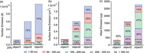
Three different objects taking approximately 1 h, 4 h, and 7 h to print were investigated using the same filament, printer and settings. The particle emissions (TP) segregated by different sizes are shown in . The total number emissions were 1.3 × 10¹², 6 × 10¹² and 1.1 × 10¹³ particles and the total mass emissions were 3.4 × 10², 1.6 × 10³ and 2.8 × 10³ μg, respectively. Regarding particle number emissions (), about 70% was from particles less than 50 nm and more than 90% was from particles less than 100 nm, consistent with Kim et al. (Citation2015); whereas for mass emissions (), more than 80% of the emissions came from particles larger than 100 nm. More than 60% of surface area emissions was from 50–200 nm particles (), between number and mass-dominant sizes. Detailed overall emissions from a print job as a function of particle size are shown in Figure S9. Ratios of particle emissions separated by size over the total emissions were relatively constant (), especially comparing between longer print times when aerosol dynamic processes reach steady state.
Figure 5. Particle number (a), surface area (b) and mass (c) emissions for ABS filament d green color on printer A for 3 objects taking about 1 h, 4 h, and 7 h to print. Each bar indicates the emission (TP) from one print object; colors indicate different particle size ranges. Values on the colored bars are the ratios of emissions from such particle size range over total emissions.
To explore the relationship between overall emission and print object further, 11 objects of different sizes and shapes were printed. Object mass varied from 6 g to more than 130 g, corresponding to number emissions from approximately 1011 to 1013 particles. A fairly linear relationship between total particle emissions and print object mass was observed (Figure S10), with the small amount of variability due to print object shape. The slope of the regression fit gives the yield; total particle emission from printing an object over mass of filament consumed, or mass of printed object. To simplify the determination of yields, in the following we estimate yields from each print job by the ratio of TP over object mass. Ratios give fairly similar yields to those calculated by slopes, with uncertainty below 20%.
One could also use print time to determine yield (TP/time, i.e., emission rate), which is related to yield normalized by object mass depending on filament feed rate. However, this might lead to some uncertainties since for a similar object mass, different printers have different filament feed rates. Also a more complex object can take longer time to print than a simpler one. In these cases, yields normalized to print time will underestimate emissions. Because of these issues, in this study, all emissions were normalized to object mass. Yields can also be determined for any particle size range and emission parameter. Once the yield has been established for a given printer-filament combination, it can be used to estimate overall emissions for any object printed under that condition. Specific parameters that affect 3D printer particle yields are now compared.
3.3. Factors that may influence particle emissions
Filament color, filament brand, printer brand and filament material may affect particle emissions. Detailed results of all these various comparisons can be found in the SI (Section S10), here we provide a summary of findings.
Experiments were designed to investigate the factors controlling particle emissions, including printer brand (A, B, C), filament brand (a, b, c, d, f) and filament color (red and white). For ABS a 4 × 2 × 2 full factorial design was applied and for PLA a 3 × 3 × 2 full factorial design was applied, using overall print job particle number yield (TP/object mass) as the dependent variable. A three-way analysis of variance test was used to determine the dominate factors influencing particle number yields amongst filament color, filament brand and printer brand for a given filament material. For ABS, both printer brand and filament brand had statistically significant effects on emissions (p < 0.0001), while filament color did not. In addition to these main effects, there was an interaction effect combining printer brand and filament brand (p < 0.0001), demonstrated by the impact on particle emissions from filament brand also depending on printer brand. ABS filament brand had the largest effect, where filament brand d (a high emitter) contributed a large part of this difference. Printer brand had the second most significant effect, while filament color only had a minor effect. For PLA, printer brand contributed more to emission variation than filament brand and filament color, however, the effects of all factors were not statistically significant. Observation results are in the SI Sections S10.1 to S10.3; Table S4 shows the particle number yields, surface area yields, mass yields and particle sizes grouped by printer-filament combinations.
The type of filament material used often depends on how the print object will be utilized. Many printers can only run a certain type of filament material, whereas some can run multiple types of material. When only changing filament material and controlling all other conditions (however extruder temperature is associated with material), significant differences on particle number yields from ABS versus PLA were observed (SI Section S10.4). Overall, ABS number yields were 3 to 104 times of that of PLA yields for a given printer brand and filament brand, the variation depended on printer brand. (Note that some PLA filaments with substantial levels of additives can have much higher particles emissions.)
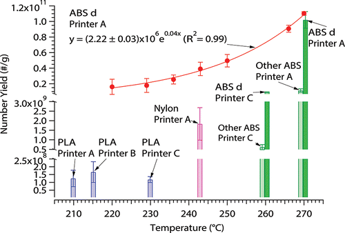
Since the formation of particles from FDM 3D printers is mainly linked to emissions of SVCs from the heated plastics, higher extruder temperatures should produce higher SVC emissions and hence aerosols that are formed. When the same object was printed using ABS brand d on printer A at varying extruder temperatures, an exponential relationship tended to fit extruder temperatures and particle number yields (). Adams et al. (Citation1999) found a similar trend for particulate emissions from commercial polypropylene processing, a process similar to FDM 3D printing where heated plastic resins (204–318°C) are extruded from a die. This exponential trend likely reflects the relationship between vapor pressure of components in the filament that produce particles and temperature, since particles are formed from emitted vapors. Extruder temperature could provide a unifying explanation for many of the differences in observed emissions from different printer brands and filament materials. In , comparing ABS brand d on printer A and printer C (dark green bars), the printer with higher extruder temperature emitted more particles, which was also true for other ABS brands (light green bars) on the two printers. No strong relationship between extruder temperature and emissions was found for the PLA tested (blue bars). In terms of particle size, average particle GMDs over the print period decreased when extruder temperature increased (Figure S15). When extruder temperature is high, more SVCs are generated thus forming more small particles by nucleation. At lower extruder temperatures, the nucleation rates from SVCs are lower and more vapors may condense on the formed particles increasing particle size. Therefore, reducing extruder temperature as much as feasible could be the easiest way to reduce overall emissions. Take printer A in this study as an example, the default extruder temperature was 270°C for ABS. The printer appeared to work well even at 220°C and particle number yields were reduced by a factor of ∼6. Another way to reduce particle emissions is to use materials that have lower melting temperatures, as demonstrated by generally lower emissions for PLA.
Figure 6. Average particle number yields for ABS, PLA, and nylon on various printers as a function of extruder temperature. The red circles represent ABS d filament on printer A at various extruder temperatures, with an exponential curve fitting in red line. The bars represent PLA (blue), nylon (pink), and ABS (green) filaments on various printers. Error bars are the standard error of the mean for repeated measurements.
Another potential source of SVCs might be a heated build plate where the printed object is attached, designed to minimize object warping during printing. It was found that the heating build plate did not significantly increase particle number emissions, but did increase particle sizes (SI Section S10.6). These results are consistent with expected aerosol dynamics. Heating the build plate may produce SVCs through contact with the printed layers. While the plate temperature (100°C for ABS) is much lower than the extruder (270°C), and the emitted vapors are not confined to a small region as for the extruder nozzle and fresh emitted plastic, the vapors do not reach concentrations to form new particles, but can condense on the existing particles, leading to increase in particle sizes and thus mass yields. The effect of heating build plate for PLA was not significant; probably because the build plate temperature for PLA was too low (50°C) to generate significant concentrations of vapors, consistent with low vapor emissions (i.e., particle emissions) from PLA in general due to lower extruder temperatures.
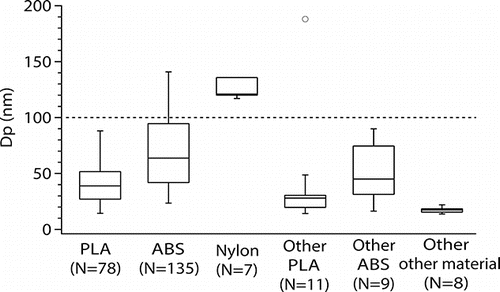
An overall summary of particle emissions for the filament materials tested is shown in . ABS yield range covered that of nylon but was wider, though the median of ABS yield was an order of magnitude higher than nylon, mainly driven by one unusually high emitting ABS filament brand. There was large uncertainty between different PLA runs, a high emitting PLA was equivalent to ABS, but overall, PLA yield was more than two order of magnitude lower than ABS. Some emissions from PLA were too low to be detected (maximum particle concentration less than 10 #/cm3 during print with background concentration less than 1 #/cm3 before print), which was never observed for ABS or nylon. The corresponding median mass yields for PLA, ABS and nylon were 0.02, 20.1 and 7.7 μg/g, respectively. For particle size, the average geometric mean diameters (GMDs) for the print period are shown in . GMDs for nylon and some ABS prints were larger than 100 nm, but all PLA prints produced particles smaller than 100 nm. A summary breaking down emissions into categories of filament brand and color, printer brand, and build plate heating is shown in Figure S16. To summarize the factors that control the emissions, filament material was the most important factor, which contributes in general 2 order of magnitude difference in particle number yields. Filament brand is the second most important factor, in this study, one high emitter was found for ABS and one for PLA, which had one to two order of magnitude larger number yields than regular filaments. This result shows that some minor unknown constituents can have a very large effect on emissions. For ABS, printer brand had a larger effect than filament color, while it was the opposite for PLA; however, these effects were much smaller than that of filament brand. Build plate heating had even smaller effect on number yield.
Figure 7. Particle number yields (TP/object mass) for various printer and filament combinations in this study (PLA, ABS, and nylon) and other published work on 3D printers (Other PLA, Other ABS, and Other other material) (Azimi et al. Citation2016; Kim et al. Citation2015; Stabile et al. Citation2017; Steinle Citation2016; Yi et al. Citation2016). The lines in the boxes indicate the medians; the top and bottom of the boxes indicate the 75% and 25% quartiles; the top and bottom of whiskers indicate the maximum and minimum values. N indicates the number of data points.
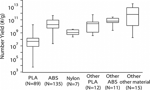
Figure 8. Average geometric mean diameters (GMDs) of particles throughout the printing period for materials tested in this study (PLA, ABS and nylon), compared to averaged mean or mode (most frequent) diameters from previous studies (Other PLA, Other ABS and Other other material) (Kim et al. Citation2015; Stabile et al. Citation2017; Steinle Citation2016; Stephens et al. Citation2013; Yi et al. Citation2016; Zontek et al. Citation2017). The lines in the boxes indicate the medians; the top and bottom of the boxes indicate the 75% and 25% quartiles; the top and bottom of whiskers indicate the maximum and minimum, except the one outlier for other PLA. N indicates the number of data points.
3.4. Overall synthesis and perspectives
The particle number yields of previous studies (including 10 printers and 33 filaments, references listed in figure caption) and this study are compared in . All previous studies have reported number yields ranging from 108 to 1013 #/g, although there are large uncertainties in conversion of reported data to yields, due to differences in experimental settings and data analyses methods. Our results were overlapping with the previous studies except for some PLA. In other studies, when short print times were applied, the average emission rates were dominated by number concentration peaks near the start of the print job, resulting in larger number yields compared to this study. The range of average GMD during the printing period was comparable to previous studies, except for nylon ().
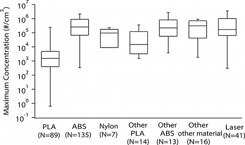
and roughly compare FDM 3D printer particle emissions to that reported for laser printers (which follow a different printing protocol). Average emission rates for all studies were in the range of 108–1012 #/min (excluding some of our PLA results, which were lower). The range for maximum particle concentrations observed during a print job was 103–106 #/cm3 (again excluding some PLA cases). Overall, the particle emissions from FDM 3D printers are comparable to laser printers in terms of particle number concentrations.
Figure 9. Average particle number emission rates (PERs) during printing period for various materials tested in this study (PLA, ABS and nylon) and previous studies (Other PLA, Other ABS, and Other other material) (Azimi et al. Citation2016; Kim et al. Citation2015; Stabile et al. Citation2017; Steinle Citation2016; Stephens et al. Citation2013; Yi et al. Citation2016), compared to laser printers (Laser) (He et al. Citation2007; Koivisto et al. Citation2010; Scungio et al. Citation2017; Salthammer et al. Citation2012). The lines in the boxes indicate the medians; the top and bottom of the boxes indicate the 75% and 25% quartiles; the top and bottom of whiskers indicate the maximum and minimum values. N indicates the number of data points.
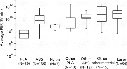
Figure 10. Maximum particle number concentrations including all experiments (Table S2) during printing period for various materials tested in this study (PLA, ABS, and nylon), and previous studies on 3D printers (Other PLA, Other ABS, and Other other material) (Azimi et al. Citation2016; Deng et al. Citation2016; Kim et al. Citation2015; Stabile et al. Citation2017; Steinle Citation2016; Stephens et al. Citation2013; Yi et al. Citation2016; Zontek et al. 2016), compared to laser printers (Laser) (Koivisto et al. Citation2010; Uhde et al. Citation2006; Wensing et al. Citation2008; Byeon and Kim Citation2012; Morawska et al. Citation2009; Schripp et al. Citation2008; Wang et al. Citation2011). The lines in the boxes indicate the medians; the top and bottom of the boxes indicate the 75% and 25% quartiles; the top and bottom of whiskers indicate the maximum and minimum values. N indicates the number of data points.
To allow more quantitative comparisons between various studies, establishment of a standard test method is critical. Here we have followed the Blue Angel Method (BAM Citation2012), which was developed for laser printers. This established method could be the bases for developing a test protocol for consumer 3D printers. Based on our findings we recommend using yield as the parameter to evaluate emissions and to compare among diverse printer-filament combinations. A standard print time or print object mass is also recommended so that the emissions are not dominated by the initial burst in particle numbers or non-uniform emission profiles observed for some printers. A list of suggestions for a standard testing protocol inspired from the Blue Angel Method is given in the SI section S11.
Since a very small mass fraction (on orders of ppm) of the filament might dictate the particle emissions, which was observed as high emitting filaments in this study for both ABS and PLA, the properties of bulk filament will not provide insight on overall printer emissions. It would seem reasonable to test (and manufactures possibly publish) emissions from the material filaments are composed of as a function of temperature. An industry acceptable standard test could be developed, which would remove all variability associated with running the filaments on different printers operating under different user selected conditions and environments.
4. Summary
FDM 3D printers emit large quantities of non-engineered nano or ultrafine particles. The maximum instantaneous particle number concentration in our test chamber exceeded 106 #/cm3 and the maximum particle number emission rate was 1011 #/min. Most particles generated were typically smaller than 100 nm. Differences in emissions primarily depend on the extruder temperature, which can largely account for differences between filament material and printer brand. Other conditions such as filament color and build plate temperature have smaller effects. Filament brand, likely through differences in trace components in the bulk material, can also have a substantial effect on emissions. A standardized testing and data analysis method is needed to allow comparisons between various research results and the setting of acceptable emission standards. The potential toxicity of these particles to humans is largely unknown and should be tested since particle composition may substantially differ from that of the bulk filament.
UAST_1342029_Supplementary_File.zip
Download Zip (11.2 MB)Funding
This work was funded by Underwriters Laboratories, Inc.
References
- Adams, K., Bankston, J., Barlow, A., Holdren, M. W., Meyer, J., and Marchesani, V. J. (1999). Development of Emission Factors for Polypropylene Processing. J. Air Waste Manag. Assoc., 49(1):49–56.
- ASTM. (2013). ASTM D6670-13, Standard Practice for Full-Scale Chamber Determination of Volatile Organic Emissions from Indoor Materials/Products. American Society for Testing and Materials International, West Conshohocken, PA.
- Alto, P. (2015). Global 3D printing market to reach $20.2 billion in 2019 | Canalys. Retrieved from http://www.canalys.com/newsroom/global-3d-printing-market-reach-202-billion-2019.
- Azimi, P., Zhao, D., Pouzet, C., Crain, N. E., and Stephens, B. (2016). Emissions of Ultrafine Particles and Volatile Organic Compounds from Commercially Available Desktop Three-Dimensional Printers with Multiple Filaments. Environ. Sci. Technol., 50(3):1260–1268.
- BAM, Federal Institute for Materials Research and Testing. (2012). Test Method for the Determination of Emissions from Hardcopy Devices within the Award of the Blue Angel Ecolabel for Equipment with Printing Function according to RAL-UZ-171. BAM, St. Augustin, Germany.
- Byeon, J., and Kim, J. -W. (2012). Particle Emission from Laser Printers with Different Printing Speeds. Atmos. Environ., 54:272–276.
- Curtius, J. (2006). Nucleation of Atmospheric Aerosol Particles. Comptes Rendus Physique, 7(9,10):1027–1045.
- Deng, Y., Cao, S. -J., Chen, A., and Guo, Y. (2016). The Impact of Manufacturing Parameters on Submicron Particle Emissions from a Desktop 3D Printer in the Perspective of Emission Reduction. Build. Environ., 104:311–319.
- ECMA International. (2015). ECMA-328 Standard 7th Edition, Determination of Chemical Emission Rates from Electronic Equipment. ECMA International, Geneva. www.ecma-international.org.
- Harrop, J. (2015). Applications of 3D Printing 2014–2024: Forecasts, Markets, Players: IDTechEx. Retrieved from http://www.idtechex.com/research/reports/applications-of-3d-printing-2014-2024-forecasts-markets-players-000385.asp.
- He, C., Morawska, L., and Taplin, L. (2007). Particle Emission Characteristics of Office Printers. Environ. Sci. Technol., 41(17):6039–6045.
- Kim, Y., Yoon, C., Ham, S., Park, J., Kim, S., Kwon, O., and Tsai, P. -J. (2015). Emissions of Nanoparticles and Gaseous Material from 3D Printer Operation. Environ. Sci. Technol., 49(20):12044–12053.
- Koivisto, A. J., Hussein, T., Niemelä, R., Tuomi, T., and Hämeri, K. (2010). Impact of Particle Emissions of New Laser Printers on Modeled Office Room. Atmos. Environ., 44(17):2140–2146.
- MatterHackers. (2015). 3D Printer Filament Comparison. Retrieved from https://www.matterhackers.com/3d-printer-filament-compare.
- Morawska, L., He, C., Johnson, G., Jayaratne, R., Salthammer, T., Wang, H., Uhde, E., Bostrom, T., Modini, R., Ayoko, G., McGarry, P., and Wensing, M. (2009). An Investigation into the Characteristics and Formation Mechanisms of Particles Originating from the Operation of Laser Printers. Environ. Sci. Technol., 43:1015–1022.
- Ragan, S. (2013). Plastics for 3D Printing. MAKE: Ultimate Guide to 3D Printing, 22.
- Rutkowski, J. V., and Levin, B. C. (1986). Acrylonitrile–Butadiene–Styrene Copolymers (ABS): Pyrolysis and Combustion Products and their Toxicity—a Review of the Literature. Fire Mater, 10(3,4):93–105.
- Salthammer, T., Schripp, T., Uhde, E., and Wensing, M. (2012). Aerosols Generated by Hardcopy Devices and Other Electrical Appliances. Environ. Pollut., 169:167–174.
- Schripp, T., Wensing, M., Uhde, E., Salthammer, T., He, C., and Morawska, L. (2008). Evaluation of Ultrafine Particle Emissions from Laser Printers Using Emission Test Chambers. Environ. Sci. Technol., 42(12):4338–4343.
- Scungio, M., Vitanza, T., Stabile, L., Buonanno, G., and Morawska, L. (2017). Characterization of Particle Emission from Laser Printers. Sci. Total Environ., 586:623–630.
- Stabile, L., Scungio, M., Buonanno, G., Arpino, F., and Ficco, G. (2017). Airborne Particle Emission of a Commercial 3D Printer: The Effect of Filament Material and Printing Temperature. Indoor Air, 27:398–408.
- Steinle, P. (2016). Characterization of Emissions from a Desktop 3D Printer and Indoor Air Measurements in Office Settings. J. of Occup. Environ. Hyg., 13(2):121–132.
- Stephens, B., Azimi, P., El Orch, Z., and Ramos, T. (2013). Ultrafine Particle Emissions from Desktop 3D Printers. Atmos. Environ., 79:334–339.
- Uhde, E., He, C., and Wensing, M. (2006). Characterization of Ultra-fine Particle Emissions from a Laser Printer. Proceedings of Healthy Buildings, 479–482.
- UL. (2014). UL 2823, UL GREENGUARD Certification Program Method for Measuring and Evaluating Chemical and Particle Emissions from Electronic Equipment Using Dynamic Environmental Chambers. Underwriters Laboratories, Northbrook, IL.
- Unwin, J., Coldwell, M. R., Keen, C., and McAlinden, J. J. (2013). Airborne Emissions of Carcinogens and Respiratory Sensitizers during Thermal Processing of Plastics. Annals of Occup. Hyg., 57(3):399–406.
- Wang, Z. -M., Wagner, J., and Wall, S. (2011). Characterization of Laser Printer Nanoparticle and VOC Emissions, Formation Mechanisms, and Strategies to Reduce Airborne Exposures. Aerosol Sci. Technol., 45(9):1060–1068.
- Wensing, M., Schripp, T., Uhde, E., Salthammer, T. (2008). Ultra-Fine Particles Release from Hardcopy Devices: Sources, Real-Room Measurements and Efficiency of Filter Accessories. Sci. Total Environ., 407:418–427.
- Yi, J., LeBouf, R. F., Duling, M. G., Nurkiewicz, T., Chen, B. T., Schwegler-Berry, D., Virji, M. A., and Stefaniak, A. B. (2016). Emission of Particulate Matter from a Desktop Three-Dimensional (3D) Printer. J. Toxicol. and Environ. Health. Part A, 79(11):453–465.
- Yoon, H. I., Hong, Y-C., Cho, S-H., Kim, H., Sohn, J. R., Kwon, M., Park, S-H., Cho, M-H., and Cheong, H-K. (2010). Exposure to Volatile Organic Compounds and Loss of Pulmonary Function in the Elderly. Eur. Respir. J., 36:1270–1276.
- Zontek, T. L., Ogle, B. R., Jankovic, J. T., and Hollenbeck, S. M. (2017). An Exposure Assessment of Desktop 3D Printing. J. Chem. Health Saf., 24(2):15–25.
- Zukas, V., and Zukas, J. A. (2015). An Introduction to 3D Printing. First Edition Design Publishing, Sarasota, FL.
