 ?Mathematical formulae have been encoded as MathML and are displayed in this HTML version using MathJax in order to improve their display. Uncheck the box to turn MathJax off. This feature requires Javascript. Click on a formula to zoom.
ABSTRACT
Accurate measurement of particle size distribution using electrical-mobility techniques requires knowledge of the charging state of the sampled particles. A consistent particle charge distribution is possible with bipolar diffusion chargers operated under steady-state condition. Theoretical steady-state charge distributions for bipolar charging are well established but recent studies have shown that the performance of particle chargers is a strong function of particle size, particle concentration, ion source, and charger operating conditions. Most of these studies have focused on particles smaller than 100 nm and the applicability of these results for particles larger than 100 nm must be investigated. In this study, experimentally obtained singly-charged and doubly-charged fractions are compared against theoretical predictions for particles in the size range of 100 to 900 nm. The experimental results show that the commercial soft X-ray charger performs as theoretically-predicted over the range of conditions studied while the performance of other commonly used radioactive chargers (85Kr and 210Po) are dependent on source strengths, flowrates, particle charge polarities, and particle sizes. From measurements of particle residence times and ion concentrations in different test bipolar chargers, prior observations of flowrate-dependent charging fractions can be explained. Additionally, the results from this study are used to determine an acceptable time period for usage of the commercial TSI 3077A 85Kr chargers for steady-state charging as a function of flowrate.
Copyright © 2018 American Association for Aerosol Research
EDITOR:
1. Introduction
The size distributions of particles smaller than 500 nm can be precisely measured using electrical-mobility technique (Knutson and Whitby Citation1975). Electrical-mobility measurements require particles to carry a known number of charges and this is commonly achieved by passing particles through bipolar diffusion chargers (Thomas and Rimberg Citation1967). In commonly used bipolar chargers, gas molecules are ionized by high-energy rays generated from the decay of radioactive sources within the unit. The diffusion of the generated bipolar ions onto aerosol particles passing through the charger, results in the particles obtaining a distribution of charges. The charge distribution on the particles exiting the bipolar charger is dependent on particle size, residence time, initial particle charge status, particle concentration, ion mobilities, and ion concentrations. The ideal operation of the bipolar charger would result in particles attaining a steady-state charge distribution that would only depend on particle size (Fuchs Citation1963). With steady-state bipolar diffusion charging, aerosol particles can attain a predictable charge distribution independent of their initial charge state, making this charging process ideal for electrical-mobility based particle size distribution measurements. The empirical fit of Wiedensohler (Citation1988) for the steady-state solution of Fuchs (Citation1963) model is widely used to predict submicron particle charging efficiencies.
Initial experimental studies of particle charging with radioactive bipolar chargers showed that near steady-state bipolar charge distributions can be achieved with several different radioactive sources (Liu and Pui Citation1974a; John and Davis Citation1974; Kojima Citation1978). Liu and Pui (Citation1974a) showed that particles in the diameter range of 0.5 to 2 µm acquired an equilibrium charge distribution when passing through a 41 MBq 85Kr charger at flowrate of 3 l·min−1. Even with a lower activity source (37 MBq 85Kr) and a higher aerosol flowrate (24 l·min−1), John and Davis (Citation1974) showed that spherical submicron particles can be brought to near equilibrium charge distribution. Such initial studies demonstrating the robust charging characteristics of custom-built radioactive bipolar chargers have resulted in their wide-spread use for aerosol mobility analysis.
Recently, some concerns have been raised about the effect of operating conditions on the performance of commercial bipolar chargers. Experimental tests have shown that aerosol charging probabilities with commercial bipolar chargers (e.g., TSI 3077) are strongly dependent on particle diameter and flowrate for particles smaller than 100 nm (He and Dhaniyala Citation2014, Jiang et al. Citation2014, Kallinger and Szymanski Citation2015). The non-ideal performance of these bipolar chargers, which have different geometries and dimensions compared with the units used in earlier research studies (e.g., Liu and Pui Citation1974a; John and Davis Citation1974), was attributed to the inadequate residence time of particles in them. Subsequently, for commercial 85Kr chargers, a modification to the flow entrance region that resulted in enhanced interaction between particles and ions was recently introduced (TSI 3007022). While the design modifications are likely to result in ideal operation of commercial bipolar chargers for sub-100nm particles, the performance limits of these chargers when used with larger particles must now be established.
Here, we examine the effect of flowrate, particle size, and incoming charge polarity on the performance of widely-used chargers – 85Kr, 210Po and soft X-ray – for spherical particles in the size range of 100 nm to 900 nm. The test air flowrates were selected to be consistent with the range of operating conditions common with typical mobility analyzers (0.3 to 5.0 l·min−1). Pre-charged particles were used as test aerosol for two reasons. First, the steady-state operation of the chargers should not depend on the incoming charge state of the particles (Fuchs Citation1963). Second, pre-charged particles are commonly encountered in laboratory experiments, e.g., particles generated by atomizers (Forsyth et al. Citation1998), and sometimes in the ambient, e.g., particles near powerlines (J-Fatokun et al. Citation2010). The experimental determined charge fractions were compared against the predictions of Boltzmann equilibrium charge distribution and the empirical equation of Wiedensohler (Citation1988).
2. Experiment setup and calculation method
The radioactive bipolar chargers studied here were: the TSI 3077 85Kr charger, with an activity of 41 MBq beta source; the TSI 3077A 85Kr charger, with an activity of 221 MBq beta source; a 210Po aerosol charger with a single 18.5 MBq 210Po strip (NRD 2U500) that generates alpha rays with a maximum energy of 5.3 MeV; and a soft x-ray charger (TSI 3088). The detailed parameters of these test bipolar chargers are summarized in . The housing of the 210Po charger was chosen to be similar to that of the 85Kr unit (internal volume of ∼110 cm3; inlet and outlet tubes with inner diameters of 0.44 cm). The tests with the 85Kr chargers were performed both with and without a recently introduced flow modification inlet insert. The TSI insert (TSI 3007022; TSI Application Note 3007-001 [A4]) is a nozzle inserted in charger entrance tube to increase flow recirculation towards particle steady-state charging.
Table 1. Parameters of the tested bipolar chargers.
The experimental setup used for the charger efficiency tests is shown in . Tests were conducted with solid particles generated by atomizing a solution of ammonium sulfate in Milli-Q water. To confirm the near-sphericity of these test particles, a select set of experiments were conducted with spherical liquid particles generated by atomizing dioctyl sebacate (DOS) in isopropanol. The tests were conducted with particle concentrations ranging from 500–3000 cm−3.
Figure 1. Schematic diagram of the experimental setup for particle charging fraction measurements with different bipolar chargers (a) CPC calibration; (b) particle penetration through test bipolar chargers; (c) particle charging efficiency measurement using the test bipolar charger; (d) experiment schematic diagram for particle residence time in a bipolar charger measurement.
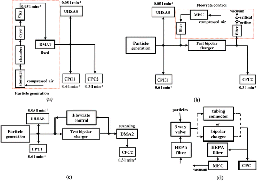
In all tests, the generated particles were sent to a cylindrical chamber (55 liters) to dampen any fluctuations in their size distributions. The aerosol flow was then passed through a silica gel diffusion dryer to dry the particles. The generated particles were charge neutralized by passing them through a 27 MBq 85Kr charger (TSI 3077) before being sent through a differential mobility analyzer (DMA). The DMA (labeled DMA1 in ) is custom-built, with large inner and outer radii (0.1 and 0.1102 m, respectively), that allows for classification of particles over a size range of 100 nm to 1 µm at high resolution. DMA1 was operated at a fixed voltage with a sheath flow rate () of 9.0 l·min−1 and an aerosol flow rate (
) of 0.95 l·min−1. The DMA sheath/excess flow was recirculated with an active carbon filter (GE VACU-GUARD 150) and a silica gel dryer in place to prevent build-up of isopropanol or water-vapor in the DMA sheath flow. This is to ensure that the gas composition entering the bipolar charger is unchanged over time, as the ion properties are dependent on the gas composition.
To ensure that the generated mono-mobility particles were also nearly mono-disperse in size, the concentrations of the atomized solutions were appropriately chosen, following the approach of He et al. (Citation2015). The mono-dispersity of the particles from the DMA1 was further confirmed by measuring the size distribution of the DMA-classified particles using two techniques – optical sizing for particles smaller than 1 µm using an Ultra-High Sensitivity Aerosol Spectrometer (UHSAS; DMT Inc.) and aerodynamic sizing for larger particles using an Aerodynamic Particle Sizer (APS; TSI 3321). Additional detail about solution concentration and the results of monodisperse test aerosol is included in the online Supplemental Information (SI).
To measure charge fractions, the concentration of particles of different charge numbers downstream of the charger must be compared to the total particle concentrations upstream of the charger. For accurate measurements, the relative detection efficiency of the two condensation particle counters (CPCs) used in this study must be established. For these experiments, the size-classified particles from DMA1 were sampled simultaneously by the two CPCs. The relative detection efficiency of the two CPCs, , was measured as the ratio of particle concentrations (
) measured by the upstream CPC (labeled as CPC1 in ; model TSI 3781) and downstream CPC (labeled as CPC2; model TSI 3775) for different selected mean-mobility particle sizes (Dp) from DMA1 as:
[1]
[1]
The next experiment conducted was to measure the size-dependent particle penetration of the test bipolar chargers using the experimental setup shown in . For these experiments, monodisperse particles were generated as before (i.e. using the “Particle generation” system shown in and this system is shown as a single box in the schematic diagrams in and ). The DMA1 was operated with the same flowrates as in the first experiment ( = 9.0 l·min−1;
= 0.95 l·min−1). The concentrations of particles from DMA1 were measured by the two CPCs before and after the test charger. The particle concentrations upstream (
) and downstream (
) were measured for the penetration calculation. The tests were conducted with three flowrates through the test chargers: 0.3, 0.93, and 4.0 l·min−1. To ensure that the desired flow passed through the charger for these cases, makeup flow was added upstream of the test charger. For a test flowrate of 0.93 and 4.0 l·min−1, a mass flow controller (MFC; Alicat) was used to control the makeup flow, and a critical orifice was used in the bypass line to ensure desired flowrates through the test charger while maintaining an aerosol flowrate of 0.95 l·min−1 through the DMA1 and CPC2 flowrate of 0.3 l·min−1. The penetration of the test charger,
, was then determined as a function of particle size
and flow rate
as:
[2]
[2]
The particle charging fractions of the different test bipolar chargers were then determined using a tandem DMA (TDMA) experimental setup (e.g., Stein et al. Citation1994), shown in (note that the “Flowrate control” box in the diagram represents the flow control system shown in ). The charge polarity of the test particles was controlled by varying the polarity of the fixed voltage applied to DMA1. The total concentrations of the monodisperse test particles were measured by CPC1. Downstream of the test charger, a second DMA (DMA2; TSI 3081) was operated in a scanning mode to obtain the mobility distribution of particles exiting the charger. The polarity of the scanning voltage applied to the DMA2 was switched to classify either positively- or negatively-charged particles, as desired.
To determine the charging efficiencies of the test chargers, the following procedure was carried out: the mobility distributions of the charged particles exiting the test charger were determined from a 3-min DMA2 scan and the signal is recorded as . Then, the test charger was removed from the setup and replaced with a conductive tubing of the same length as the charger. Without the test charger in place, DMA2 was scanned over 3-min to obtain the mobility distribution of particles exiting DMA1 and the signal is recorded as
. The mobility distributions with and without the test chargers were repeated 3 times for each test case. During each of these tests, the average upstream particle concentrations
were measured by CPC1.
As the transfer function of the scanning DMA2 has the same contribution to the particle concentration signals obtained with and without the charger in place, and
, the charging fraction (
) can be simply determined as:
[3]
[3] where V is the voltage applied on DMA2 and
[4]
[4]
In Equation (Equation3[3]
[3] ), the numerator
is proportional to the concentrations of particles with a selected charge number (i) exiting the charger. The summation limits
and
are the minimum and maximum DMA voltages corresponding to the extraction of these particles from the DMA2. The denominator
, obtained from measurements without the charger in place, is proportional to the total concentration of particles entering the test charger. The summation limits,
and
are the minimum and maximum voltages of the entire DMA2 scan. By appropriately choosing the sheath flow, scanning voltage range, and scan time of DMA2, the range of voltages for particles of different charge numbers will be distinct. In this study, we restrict our measurements to determine the singly- and doubly-charged fractions of particles in the size range of 100 to 900 nm.
To characterize the performance of test chargers as a function of their product (“nt”) of ion concentration (n) and residence time (t), we experimentally measured the two quantities for different chargers. The particle residence time (tr) for all the test chargers was measured using the signal response experimental setup (Quant et al. Citation1992), shown in . For residence time measurements, an electrically-controlled 3-way valve (GEMS Sensors & Controls) and a HEPA filter were used to alternate between aerosol and clean flows. The output from the 3-way valve was passed to a CPC either through the test charger or a short tubing connector. When the 3-way valve was operated to switch from clean to aerosol flow, the CPC signal rises from zero to the final particle concentration value over time. Without the bipolar charger (i.e., just with the short connector tubing), the signal temporal characteristics depends on the response time of the 3-way valve, the CPC response time, and particle transmission time through the tubing and CPC. When the aerosol flow is passed through the test charger, the temporal response additionally depends on flow characteristic of the tested charger. Assuming that the individual systems (charger, valve, and CPC) are linear, the particle residence time in the charger, t, can be calculated as a difference in the response times of the two systems for a selected change in concentration. Thus, for example, the residence time for 50% of the particles to pass through the charger (t50) can be calculated as the difference in the times corresponding to 50% of the particles passing through the setups with and without the charger. The residence times through the test chargers under different flowrates were measured by adjusting the bypass flowrate controlled by a mass flow controller (MFC). Further details of the experimental setup used for residence time calculation and the analysis conducted for residence time calculation is included as SI.
For ion concentration measurements (n), the approach of Liu and Pui (Citation1974b) and de la Verpilliere et al. (Citation2015) was used. The ion concentration measurements were made for the 221MBq 85Kr and soft X-ray chargers.
3. Results and discussions
3.1. Charging fraction comparison
In the initial tests, we determined the effect of using an insert on the TSI 3077 (41 MBq 85Kr) and TSI 3077A (221 MBq 85Kr) chargers. For these experiments, the test particles were positive, singly-charged ammonium sulfate and the particles exiting the bipolar charger were classified by DMA2 operated with a negative polarity high voltage (i.e positively-charged particles were extracted out of DMA2). The measured singly-charged fractions of the 85Kr chargers, operated with an aerosol flowrate of 0.3 l·min−1, are compared with the predictions of Wiedensohler (Citation1988) and the Boltzmann's equilibrium law in . The particle charging fractions obtained using the 221 MBq 85Kr charger with an inlet insert are close to the theoretical values for almost all the tested sizes. Without the inlet insert, the charging fractions with the 221 MBq 85Kr charger are lower than the theoretically predicted values for particle diameters larger than 700 nm. With the 41 MBq 85Kr charger, the charging fractions are significantly lower than the theoretical values even with an insert in place. Using a lower activity 85Kr source, steady-state charging is not achieved for test particles in this study, though the presence of the insert helps improve the performance of the bipolar charger. With the 210Po charger, it is found that the singly-charged fraction was ∼ 40–60% lower than the theoretical prediction values. The low charging fraction with the 210Po charger is contrary to the findings with sub-50 nm particles (He and Dhaniyala Citation2014) where the tests were conducted with uncharged particles entering the chargers. The singly-charged fractions from the soft X-ray charger are close to the theoretical values for all particle sizes, which is consistent with the results of Tigges et al. (Citation2015). The uncertainty in the charging fractions is calculated as the standard deviation of three measurements as these values are larger than that calculated from error propagation.
Figure 2. The measured charging fractions of positively-charged particles exiting the bipolar charger for the case of positively-charged particles entering the bipolar charger (a) singly-charged fraction, fc,1; (b) doubly-charged fraction, fc,2. The flowrate through the bipolar chargers is 0.3 l min−1. Ammonia sulfate particles are used for singly-charging tests while DOS particles are used for doubly-charging measurements.
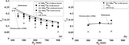
The doubly-charged positive fractions from the soft X-ray, 210Po and 221 MBq 85Kr chargers (with insert) for incoming positively-charged DOS particles with flowrate of 0.3 l·min−1 are shown in . The doubly-charged fractions with the soft X-ray and 221 MBq 85Kr chargers are seen to be close to the predictions by the Boltzmann's law and empirical equation of Wiedensohler (Citation1988). The 210Po charger, however, is again seen having significantly lower charging fraction values than the theoretical predictions over the entire range of particle sizes tested.
3.2. The effect of particle charge polarity on its charging fraction
After the initial tests () with positively-charged particles entering and exiting the bipolar chargers, further tests were conducted to determine the bipolar charger performance for other charge combinations (e.g., incoming negatively-charged particles and outgoing positively-charged particles). For these tests, the DMA1 and DMA2 central rod high voltage polarities were varied appropriately to output particles of a selected polarity combination. The singly- and doubly-charged fractions from soft X-ray, 221 MBq 85Kr and 210Po chargers for 300 nm particles entering the bipolar charger at 0.3 l min−1 are shown in for different polarity combinations.
Figure 3. Singly and doubly charging fractions obtained with different bipolar chargers when the 300 nm particles entering the tested bipolar charger are (a) positively-charged; (b) negatively-charged. The flowrate through the bipolar chargers is 0.3 l min−1. Ammonia sulfate particles are used for singly charging fraction measurements while DOS particles are used for doubly charging fraction measurements.
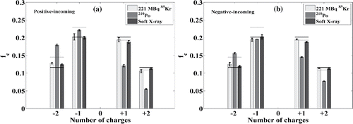
The singly- and doubly-charged fractions are seen to be close to that predicted for the soft X-ray and 221 MBq 85Kr chargers for both polarities of incoming particles. The performance of the 210Po charger, however, is not always matched with theoretical predictions. The singly-charged negative fractions from the 210Po charger are seen to be close to the theoretical predictions for both polarities of incoming particles and the fractions of positively-charged particles are always less than that predicted. The positively-charged fraction from the 210Po charger is seen to be higher when the incoming particles are negatively-charged compared to when they are positively-charged. The results suggest that the combination of the radioactive source activity and particle residence time in the 210Po charger may be insufficient to bring singly-charged incoming particles to steady-state charge distribution.
The deviation from theoretical predictions is seen to be more significant for positive-incoming than negative-incoming particles. For particles of both incoming-polarities, the inadequate neutralization results in a more negatively charged fraction than predicted theoretically. This bias towards negative charging of particles under inadequate nt product is because of the high mobility of negative ions (Hussin et al. Citation1983). Relative to positive ions, the higher mobility negative ions act to efficiently “neutralize” their oppositely-charged particles and to subsequently charge the neutral particles negatively in the short time available within the bipolar charger.
3.3. The effect of flowrate on particle charge fraction
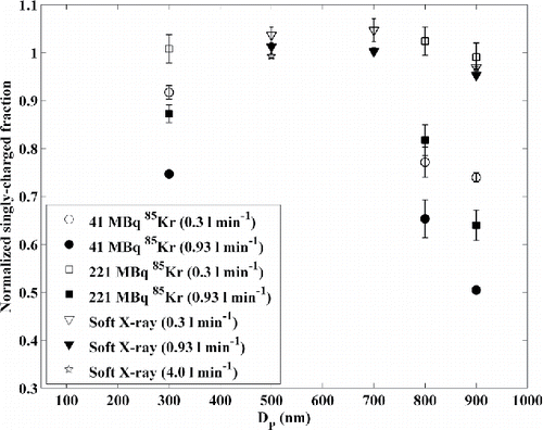
The normalized charging fractions of 300 to 900 nm particles passing through the different bipolar chargers – 41 MBq 85Kr with insert, 221 MBq 85Kr with insert and soft X-ray – at two different flowrates (0.3 and 0.93 l min−1) are shown in . The charging fractions are normalized by the predictions of Wiedensohler (Citation1988) for positive charge fractions. At a lower flowrate (0.3 l·min−1), the charged fractions of the 221 MBq 85Kr and soft X-ray chargers are seen to be close to the theoretical value, but the charged fractions obtained using the 41 MBq 85Kr charger are lower than the expected ones. At a higher flow rate (0.93 l·min−1), however, the particle charging fractions with both the 41 and 221 MBq 85Kr chargers, are lower than the theoretically expected values. With the soft X-ray charger, the measured particle charging fractions are almost independent of the flowrate, which is largely consistent with the conclusions of Yoon et al. (Citation2015) for smaller particles (30–130 nm). Furthermore, we tested the soft X-ray charger with a flowrate of 4.0 l·min−1. The near-unchanged charging fractions with the soft X-ray charger for aerosol flowrates from 0.3 to 4.0 l·min−1 suggest that this charger is ideal for use with mobility-based instruments over a wide size range of interest.
Figure 4. Normalized singly-charged positive fraction of particles when passing through different bipolar chargers at different flowrates. Here the TSI insert is used on the 41 MBq 85Kr and 221 MBq 85Kr chargers, and ammonia sulfate particles are tested. The predictions from Wiedensohler (Citation1988) are used for the normalization.
3.4. The nt product for steady–state charging
The performance of a bipolar charger is generally assumed to be governed by the product of ion concentration (n) and residence time of particles (t) in the charger (Liu and Pui Citation1974b). The ISO 15200:Citation2009(E) standard states that a nt product larger than 1013 m−3·s will result in particle steady-state charging (BS ISO 15900:2009(E), Citation2009). Here, we estimate the nt product for the different bipolar chargers and compare them against the recommended ISO standards.
3.4.1. Particle residence time in a bipolar charger
Particle residence time in a bipolar charger is generally calculated based on plug flow assumptions (e.g., Liu and Pui Citation1974b; Lee et al. Citation2005). Here, particle residence times are measured for different flowrates from the temporal response functions (as described in the SI). From the distribution of particle response times, particle residence times in the bipolar charger corresponding to different concentration levels (t10, t50, and t90) can be calculated.
The measured particle residence times in different bipolar chargers for varying flowrates are shown in . For each flowrate, the mean residence time, t50, is shown along with an error bar that represents the time range corresponding to t90 and t10. At a selected flowrate, the soft X-ray has the highest residence time of all the tested chargers. For 85Kr charger, tests were conducted with and without the TSI insert. Also, tests with the 85Kr chargers were conducted with flow entering the charger in the direction recommended by TSI (subscript f in the legend) and the opposite direction (subscript b in the legend). The tested flowrates are: 0.3, 0.93, 1.5, 2, 3, 4, and 5 l·min−1. For ease of visualization, the results for different bipolar chargers at a selected flowrate are slightly displaced in the flowrate-axis (x-axis) in . Without the insert, the residence time with opposite direction is longer than that with TSI recommended flow direction, explaining previous observations of higher charging fraction with this orientation (He and Dhaniyala Citation2014). A minimum in residence time at intermediate flowrates (∼1.0 l·min−1) is consistent with prior observations of lower charging efficiencies at these flowrates for sub-50 nm particles (He and Dhaniyala Citation2014). With the TSI insert in place, the residence times are significantly increased for flowrates from 0.9 to 2 l·min−1 while remaining largely unchanged for other flowrates. Again, with the insert the residence time is seen to be slightly longer when the bipolar charger is operated with flow entering in the opposite direction.
Figure 5. Particle residence times in a bipolar charger. Here the 85Kr charger was tested with and without an inlet insert placed on. The flow direction is following TSI recommendation (subscript “f”) and opposite (subscript “b”). The markers represent residence time for 50% particles, while the error bar represents the residence time range for 10% to 90% of particles. The calculated residence times based on plug flow assumption are also shown.
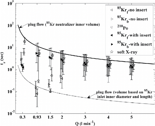
Also shown in are the residence times calculated assuming plug flow in the 85Kr charger based on the inner volume of the unit. The plug-flow residence time is greater than the observed t50 value with an inlet insert and the t90 value without an insert for most flowrates. Therefore, with the plug flow assumption, the residence time and, hence, the nt product is overestimated. Considering just the diameter of the bipolar charger inlet and the length of the unit, the shortest possible plug-flow residence time can be calculated. For a flowrate of 0.93 l·min−1, the residence time for the bipolar charger without an insert is seen to be close to this shortest residence time value.
For the 210Po charger, the residence time at flowrates less than 3.0 l·min−1 is longer than that in a 85Kr charger without the insert. This observation, combined with the expected higher ion concentration in a 210Po charger (Liu et al. Citation1986), explains the higher charging efficiencies for sub-50 nm particles in a 210Po charger compared with that in 46.8 MBq 85Kr charger (He and Dhaniyala Citation2014). However, in the current study it is observed that 300 nm diameter particles are not charged to a steady-state using a 210Po charger even at flowrate of 0.3 l·min−1 ( and ). The 300 nm 210Po charging efficiencies are lower than that obtained with the 41MBq 85Kr charger, in contrast to the observations with sub-50nm particles by He and Dhaniyala (Citation2014). A possible reason for the differing relative behaviors of the two chargers for different particle sizes is discussed further below.
3.4.2. Performance of 85Kr charger with age
The ion generation rate, S, from the soft X-ray (TSI 3088) was measured to be ∼3.31e13 m−3·s−1, which is slightly higher than that measured by de la Verpilliere et al. (Citation2015) using TSI 3087 soft X-ray (2.3e13 m−3·s−1). The ion generation rate from the 221 MBq 85Kr charger was measured to be ∼2.26e13 m−3·s−1. Assuming an ion generation rate, Si, to be linearly proportional to the source activity, A, then the ion generation rate from a new TSI 3077A (370 MBq), S0, can be calculated as 3.79e13 m−3·s−1, and the time-dependent ion generation rate can be obtained from:[5]
[5] where A0 is 370 MBq for TSI 3077A, τ is decay time constant (15.58 years; assuming a half-life of 10.8 years). The ion concentration is then calculated using following equation (Adachi et al. Citation1980)
[6]
[6] where α is the ion recombination coefficient (Bricard and Pradel Citation1966), t is particle residence time in the bipolar charger. Rather than Equation (Equation6
[6]
[6] ) a simplified form that n equals to
is widely used (e.g., Liu and Pui Citation1974b).
Using the measured ion concentrations and residence times for 85Kr and soft X-ray chargers, the relation between nt values and the normalized charging efficiencies obtained during this study and from previous experiments (He and Dhaniyala Citation2014) are shown in . The particle charging fractions are normalized by the corresponding predictions from Wiedensohler (Citation1988). Using a residence time of t30, i.e., a time that 70% of the particles reside longer than, the charging efficiencies reach expected values when the nt product is over the ISO standard. A comparison of charging efficiencies with nt product calculated with other residence time measures (t10, t40, t50, and tplug-flow) are shown in SI.
Figure 6. The effect of nt value on particle charging fraction. The t30 is used for the nt product calculation.
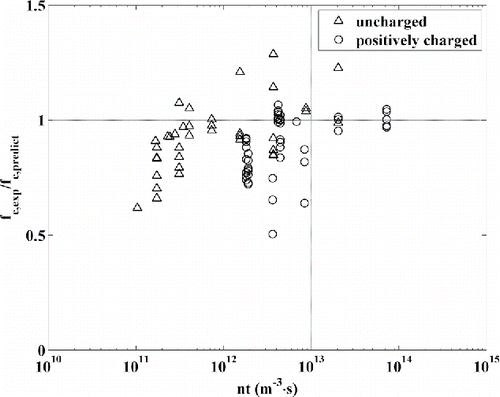
The results of suggest that a nt30 product greater than 1e13 m−3·s may be sufficient for near steady-state charging of singly-charged and uncharged particles. For a selected nt value less than 1e13, the charging efficiencies are highly variable, representing different charger performance as a function of particle size, charge polarity, flow orientation, etc. This charging efficiency data spread could indicate a limitation of our calculation of nt value assuming uniform ion concentration field and particle-size independent residence time. As shown by de la Verpilliere et al. (Citation2015), in a bipolar charger, the ion concentrations are not uniform and the flow fields are complicated. Thus, in a bipolar charger, effective nt values will be particle size-dependent and must be calculated with a combination of computational fluid dynamic (CFD) simulations and experiments. The effective nt values might more accurately help predict charger behavior as a function of operating conditions.
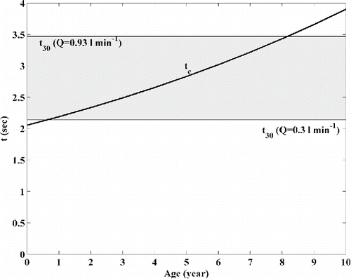
Considering the ISO standard for nt30 product, the critical residence times (tc) required as a function of age of the TSI 3077A 85Kr charger and flowrate for steady-state charging of singly-charged incoming particles, are shown in . The case considered here is of the charger with the inlet insert in place and operated in the opposite flow direction, which maximizes residence time for a given flowrate. For flowrates greater than 1.5 l·min−1, the critical residence times required are greater than the measured t30 values. This suggests that, even with a new TSI 3077A 85Kr charger, steady-state charging is not assured for charged particles for flowrates greater than 1.5 l·min−1. At a flowrate of 0.3 l·min−1, steady-state charging is only assured when a TSI 3077A 85Kr charger is less than 1 year old, while at a flowrate of 0.93 l·min−1, the bipolar charger can be operated for ∼8 years. Note that the test results for the 8-year old TSI 3077A charger shown in were obtained with the bipolar charger operated under recommended flow direction, which results in a lower residence time than for the case considered here. These results are based on calculating the age-dependent TSI 3077A charger performance assuming an ion generation rate that is linearly proportional to the source activity.
4. Summary and conclusions
An experimental study was conducted to determine the charging performance of commonly used aerosol bipolar chargers –41 MBq 85Kr, 221 MBq 85Kr, 210Po and soft X-ray chargers – using charged spherical test particles in the size range of 100 to 900 nm and a concentration range of 500 to 3000 cm−3. The performance was characterized as a function of flowrate through the bipolar charger, particle diameter, and charge polarity of the incoming particles. Singly- and doubly-charged fractions for 100 to 900 nm ammonium sulfate and DOS particles were determined for the tested bipolar chargers. The experimental results show that the 41 MBq 85Kr charger does not produce particles with steady-state charge characteristics for even the lowest flowrates and particle sizes tested. The insert at the entrance of the TSI 85Kr charger helps improve the charger performance but does not result in theoretical steady-state charging values. The 221 MBq 85Kr charger with an insert provides close to theoretical steady-state charging fractions at low flowrates (0.3 l·min−1), but the charging performance at intermediate flowrates (0.93 l·min−1) is lower than that predicted theoretically. The performance of the 18.5MBq 210Po charger is seen to be more strongly dependent on the charge state of the incoming aerosol than the other tested bipolar chargers, suggesting its inadequate nt product for aerosol neutralization. Our observations with the 210Po charger on charged particles also suggest that inadequate neutralization results in a more negatively-charged particle population than that expected under theoretical steady-state operation. With the soft X-ray charger, particles reach the predicted steady-state charging fractions at different tested flowrates (0.3 to 4.0 l·min−1) and particle sizes (100 to 900 nm). Considering that the net charge-state of the incoming particles may be unknown, it is recommended that mobility measurements be made with a soft X-ray charger.
To predict a bipolar charger performance based on nt product, particle residence times were measured and seen to be very different from that calculated based on plug flow assumption. Our analysis established that: (Equation1[1]
[1] ) the plug flow assumption overestimates the nt product value; (Equation2
[2]
[2] ) the measured flowrate-dependent residence times explain previous observations of flowrate-dependent particle charging efficiencies; and (Equation3
[3]
[3] ) the use of the insert significantly increases particle residence time in the bipolar charger for flowrates between 0.9 and 2.0 l·min−1. Under the assumption that the ion generation rate is linearly proportional to the source activity, the measured particle residence times suggest that steady-state particle charging with the commercial TSI 3077A 85Kr charger for initially charged particles is only possible for flowrates in the range of 0.3 to 1.5 l·min−1 over a limited time period that is less than the half-life of the source.
Supplemental Material
Download Zip (713.5 KB)Acknowledgments
The authors would like to thank TSI Inc. for loaning the soft X-ray charger used in this study.
Additional information
Funding
References
- Adachi, M., Okuyama, K., Kousaka, Y., and Takahashi, T. (1980). Electrical Charging of Uncharged Aerosol Particles Under at Bipolar Ion Concentrations. J. Chem. Eng. Japan, 13:55–60.
- Bricard, J., and Pradel, J. (1966). Electric Charge and Radioactivity of Naturally Occurring Aerosols. In Aerosol Science (Edited by C. N. Davies), Academic Press, New York.
- BS ISO 15900: 2009(E) (2009). Determination of particle size distribution –differential electrical mobility analysis for aerosol particles. British Standards Institute.
- de la Verpilliere, J. L., Swanson, J. J., and Boies, A. M. (2015). Unsteady bipolar diffusion charging in aerosol neutralisers: a non-dimensional approach to predict charge distribution equilibrium behavior. J. Aerosol Sci., 86:55–68.
- Forsyth, B., Liu, B. Y. H., and Romay, F. J. (1998). Particle Charge Distribution Measurement for Commonly Generated Laboratory Aerosols. Aerosol Sci. Technol., 28:489–501.
- Fuchs, N. A. (1963). On the Stationary Charge Distribution on Aerosol Particles in a Bipolar Ionic Atmosphere. Geofis pura e applicate, 56:185–193.
- He, M., Dhaniyala, S., and Wagner, M. (2015). Aerosol Filtration with Mobility-Classified Particles: Role of Multiply Charged Particles in Skewing Penetration Measurements. Aerosol Sci. Technol., 49:705–716.
- He, M., and Dhaniyala, S. (2014). Experimental Characterization of Flowrate-Dependent Bipolar Diffusion Charging Efficiencies of Sub-50nm Particles. J. Aerosol Sci., 76:175–187.
- Hussin, A., Scheibel, H. G., Becker, K. H., and Porstendörfer, J. (1983). Bipolar Diffusion Charging of Aerosol Particles – I: Experimental Results Within the Diameter Range 4–30 nm. J. Aerosol Sci., 14:671–677.
- J-Fatokun, F., Jayaratne, R., Morawska, L., Birtwhistle, D., Rachman, R., and Mengersen, K. (2010). Corona Ions from Overhead Transmission Voltage Powerlines: Effect on Direct Current Electric Field and Ambient Particle Concentration Levels. Environ. Sci. Technol., 44:526–531.
- Jiang, J., Kim, C., Wang, X., Stolzenburg, M. R., Kaufman, S. L., Qi, C., Sem, G. J., Sakurai, H., Hama, N., and McMurry, P. H. (2014). Aerosol Charge Fractions Downstream of Six Bipolar Chargers: Effects of Ion Source, Source Activity, and Flowrate. Aerosol Sci. Technol., 48:1207–1216.
- John, W., and Davis, J. W. (1974). The Measurement of the Charge Distribution on Monodisperse Aerosols. Atmos. Environ., 8:1029–1034.
- Kallinger, P., and Szymanski, W. W. (2015). Experimental Determination of the Steady-State Charging Probabilities and Particle Size Conservation in Non-Radioactive and Radioactive Bipolar Aerosol Chargers in the Size Range of 5–40 nm. J. Nanoparticle Res., 17(4):171.
- Knutson, E. O., and Whitby, K. T. (1975). Aerosol Classification by Electric Mobility: Apparatus, Theory, and Applications. J. Aerosol Sci., 6:443–451.
- Kojima, H. (1978). Measurements of Equilibrium Charge Distribution on Aerosols in Bipolar Ionic Atmosphere. Atmos. Environ., 12:2363–2368.
- Lee, H. M., Kim, C. S., Shimada, M., and Okuyama, K. (2005). Bipolar Diffusion Charging for Aerosol Nanparticle Measurement Using a Soft X-Ray Charger. J. Aerosol Sci., 36:813–829.
- Liu, B. Y. H., Pui, D. Y. H., and Lin, B. (1986). Aerosol Charge Neutralization by a Radioactive Alpha Source. Part. Part. Syst. Charact., 3:111–116.
- Liu, B. Y. H., and Pui, D. Y. H. (1974a). Equilibrium Bipolar Charge Distribution of Aerosols. J. Colloid Interface Sci., 49:305–312.
- Liu, B. Y. H., and Pui, D. Y. H. (1974b). Electrical Neutralization of Aerosols. J. Aerosol Sci., 5:465–472.
- Quant, F. R., Caldow, R., Sem, G. J., and Addison, T. J. (1992). Performance of Condensation Particle Counters with Three Continuous-Flow Designs. J. Aerosol Sci., 23:405–408.
- Stein, S. W., Turpin, B. J., Cai, X., Huang, P.-F., and McMurry, P. H. (1994). Measurements of Relative Humidity-Dependent Bounce and Density for Atmospheric Particles using the DMA-Impactor Technique. Atmos. Environ., 28:1739–1746.
- Thomas, J. W., and Rimberg, D. (1967). A Simple Method for Measuring the Average Charge on a Monodisperse Aerosol. Staub-Reinhalt, Luft, 27:18–22.
- Tigges, L., Wiedensohler, A., Weinhold, K., Gandhi, J., and Schmid, H.-J. (2015). Bipolar Charge Distribution of a Soft X-ray Diffusion Charger. J. Aerosol Sci., 90:77–86.
- Wiedensohler, A. (1988). An Approximation of the Bipolar Charge Distribution for Particles in the Submicron Size Range. J. Aerosol Sci., 19:387–389.
- Yoon, Y. H., Bong, C., and Kim, D. S. (2015). Evaluation of the Performance of a Soft X-ray Charger for the Bipolar Charging of Nanoparticles. Particuology, 18:165–169.

