 ?Mathematical formulae have been encoded as MathML and are displayed in this HTML version using MathJax in order to improve their display. Uncheck the box to turn MathJax off. This feature requires Javascript. Click on a formula to zoom.
ABSTRACT
Flow Blurring® (FB) atomization is a highly efficient method to produce aerosols. It originates from an unexpected turbulent back flow motion in the interior of the atomizer. The onset for the appearance of such pattern is dictated by a geometrical parameter, ϕ, that is, the ratio of the distance from the tip of the liquid feeding tube to the discharge orifice (H), and the diameter of the discharge orifice (D). In this work, a FB atomizer with a nominal ϕ = 1/6 was used to produce water and ethanol droplets into pressurized environments (>1 MPa). The droplet size distributions and mean droplet speeds were investigated using (1) direct visualization with an ultra-high-speed video camera coupled with an automated droplet measurement (ADM) program and (2) using a light scattering instrument. Light scattering measurements, with water and ethanol, varying the driving pressure to produce the aerosol (ΔP), indicate a power dependence of ∼2/5 of the dimensionless mean droplet diameter (/Do) on the dimensionless liquid flow rate (Q/Qo). At higher liquid flow rate, the optical resolution of the droplets is improved compared to lower volumetric flow rates, thus facilitating analyses with the ADM program. The approach outlined herein provides a guideline for characterization and implementation of the FB technology in high-pressure applications.
Copyright © 2018 American Association for Aerosol Research
EDITOR:
Introduction
Liquid atomization requires conversion of a fraction of an energy input into surface energy. In pneumatic atomization, the interaction of gas and liquid flows is typically accompanied by turbulent motions that result in the generation of droplets of relatively small size. An efficient atomization is achieved by maximizing the surface area of the liquid flow and preventing droplet coalescence simultaneously minimizing the gas expense.
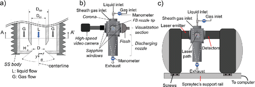
Gañán-Calvo (Citation2005) proposed the so-called Flow Blurring® (FB) mechanism for efficient atomization of liquids. In FB, an unexpected back-flow pattern in the interior of the atomizer produces small scale perturbations, thus resulting in an efficient mixing between the gas and liquid phases (Gañán-Calvo Citation2005, Citation2008) at the atomizer outlet. FB nozzle atomizers use a simple yet robust design in which the interaction of the liquid and gas flows is controlled by a geometrical parameter (ϕ), that is, the ratio H/D, where H is the gap between the tip of the liquid feeding tube (capillary) and the discharge orifice, and D is the diameter of the discharge orifice, as indicated in . The same geometrical configuration can lead to different modes of spraying only by varying ϕ. Relatively small values of ϕ lead to production of droplets with a wide range of sizes, in the FB mode. If; however, ϕ is increased above 0.6, the liquid flow forms a jet that, for a range of Weber numbers, is steady and breaks up periodically into monodisperse droplets, in what is known as flow focusing (FF) (Gañán-Calvo Citation1998). The FB technique generates from five to fifty times more surface area than other methods, for a given energy input (Gañán-Calvo Citation2005; Rosell-Llompart and Gañán-Calvo Citation2008, Simmons and Agrawal Citation2012). Such capabilities make FB nozzles suitable for many cutting-edge applications.
Figure 1. (a) Diagram of a cross-sectional view of the FB tip. Schematics of the experimental setup used for (b) high-speed visualization experiments, and (c) light-scattering measurements.
FB nozzles have been used in spectrometric techniques for generation of analyte droplets (Kovachev et al. Citation2009; Aguirre et al. Citation2010; Pereira et al. Citation2014) and in atomization of biofuels (Simmons and Agrawal Citation2012). Recently, we have proposed the direct atomization of water with FB nozzles into a combustion engine aiming at reduction of emissions (Modesto-López and Gañán-Calvo Citation2017). The approaches to use water in combustion engines include either direct injection or mixing with the fuel (Sahin et al. Citation2014; Bedford et al. Citation2000). In both cases, the size of the droplets is a key parameter influencing the droplets' evaporation timescale and their transport characteristics, and thus combustion efficiency as indicated by earlier studies (Hiroyasu and Kadota Citation1976; Witting et al. Citation1988). Most of the research on these topics has been performed at ambient or relatively low pressure conditions. However, FB in high-pressure environments, where many processes occur, remain largely unexplored. Thus, a detailed characterization of droplet size is of paramount importance to understand in those environments.
Several tools for characterization of dense sprays are available, most of which are based on the interaction of the droplets with light. High-speed tomographic approaches are also employed for such systems where the dynamics of droplets or bubbles are demanding (Johansen, Hampel, and Hjertaker, Citation2010). Nevertheless, recently Tan, and collaborators have developed a so-called automated droplet measurement (ADM) program for characterization of drops and bubbles in microfluidic systems (Chong et al. Citation2016). Here, we also demonstrate that the same tool can provide, upon careful tuning of the program operation parameters, valuable information of high-throughput sprays, in which droplets are generally polydisperse and with varying velocities.
In this work, we study the characteristics of sprays in high-pressure environments produced by a FB nozzle. We coupled real-time visual methods with light scattering techniques to obtain the size distribution and the speed profile of the aerosol droplets in the vicinity of the FB nozzle. The key process parameters controlling FB atomization are the liquid flow rate, Q, the inlet gas pressure, Po, the chamber pressure, Pi, and thus the pressure difference ΔP = Po – Pi. We also investigated a wide range of ΔP values for three different liquid flow rate to obtain a correlation in terms of dimensionless parameters.
Experimental section
Materials
Deionized (DI) water (milliQ) and absolute ethanol (Sigma-Aldrich) were used as test fluids. The spraying nozzle consisted of a stainless steel (SS) body designed in-house, in which a commercial FB® nozzle tip (Ingeniatrics Tecnologías S. L., Sevilla, Spain) was assembled (). The tip, made of a corrosion resistant plastic (LCP), had a geometrical configuration as depicted in with the diameter of the discharge orifice, D = 240 µm; the distance from the exit of the liquid feeding capillary to the discharge orifice, H = 40 µm (nominal); and thus ϕ = 1/6. The internal and external diameters of the tip's liquid feeding capillary are Dci = D and Dco = 1 mm, respectively. The angle of the discharge orifice, θ, is 120°. Hereafter, the radial direction, r, is defined as the length from the centerline of the discharge orifice toward the exterior (see ), and the axial direction, y, is the height from the discharge orifice downward, in the direction of the spray. The AA' view of the FB tip is depicted in Figure S1 in the supporting information file.
Test chamber
The in-house designed high-pressure chamber comprised three main components: (1) the FB nozzle (described above) and a corona to supply sheath gas, (2) a spray visualization section, and (3) a discharge converging flow region, as depicted in . The FB nozzle discharges into the visualization section, which consists of a cube with a cylindrical interior space. The cube had three circular perforations designed to house flat-surface, sapphire windows, thus allowing observation of the spray. The windows were purchased from IBSA LASER (Madrid, Spain) and were 5 mm thick with a diameter of 50 mm and were coated with an anti-reflective material on both planar surfaces. The sheath gas was introduced through a corona consisting of 40 cylindrical channels of 500 µm in diameter. The channels were distributed circularly around the FB nozzle and were fabricated in such a way to prevent direct interaction of the sheath gas with the spray. The gas flow rate was adjusted accordingly to achieve the desired chamber pressure. The discharge converging flow region, which has a converging shape (see white lines in and ), had the function of accelerating the flow of the aerosol, thus preventing excessive droplets' accumulation in the visualization section. The pressure in the chamber was adjusted through head loss by gradually increasing the resistance of the exhaust tube. During all experiments, the pressure was measured at the gas inlet of the FB nozzle and in the chamber interior as depicted in and . The measured pressures are gauge values, which were converted to absolute values for the calculations performed herein.
Ultra-high speed visualization experiments
An ultra-high speed Shimadzu video camera (HPV-2), capable of recording up to 106 frames-per-second (fps), was focused through one of the sapphire windows, and illuminated with a high-intensity flash placed on the opposite side (). The flash was synchronized with the video camera through an external trigger. The camera began recording 1 ms after the trigger was manually switched on. DI water or ethanol was fed to the FB nozzle with a Shimadzu high-performance liquid chromatography (HPLC) pump (model LC-10AD). The gas inlet pressure (Po) and chamber pressure (Pi) were monitored with digital, high-pressure WIKA manometers capable of measuring up to 10 MPa (model CPG1000). Additional gas was supplied through the ‘corona’ around the FB nozzle (see previous subsection), to increase the chamber pressure up to a desired value. The gas inlet pressure, Po, was varied in the range 1.2–5 MPa and, the chamber pressure, Pi, was maintained from 200 kPa to 3 MPa below Po, as indicated in each set of measurements. Typical liquid flow rates, Q, used in this work were 0.3 and 0.5 mL/min (low range), 1 mL/min (medium range), and 5 mL/min (high range).
As-recorded ultra-high-speed videos were processed with the widely known, freeware software ImageJ (Schneider et al. Citation2012) to adjust their brightness/contrast and remove optical noise before being analyzed with the ADM program. Although the processing step with ImageJ is generally unnecessary, in our case it is useful given the large number of droplets that simultaneously appear at any recording time. The frame of ultra-high speed videos had a field of view of 1.4 mm (width, x-axis) × 1.2 mm (height, y-axis), which allows analyses in a region very close to the spray emission point. Besides its superior image processing capability, the ADM program has an inherent feature of background subtracting, thus removing optical artifacts which remain static through the sequence of frames, such as stains on the surfaces of lenses and windows. The ADM data reported herein are time-averaged values over the field of view. A brief description of the ADM program is included in the Supporting Information file. For detailed software setting parameters and operation conditions refer to Chong et al. (Citation2016) and to the webpage link provided therein. The number-based droplet size distributions obtained with the ADM were converted to volume-based distributions to compare them with those from light scattering measurements (LSMs).
Light scattering measurements
LSMs were performed with a Malvern Spraytec® instrument equipped with a 632.8-nm He-Ne laser of 15 mm in diameter and with a 300-nm range lens system capable of measuring particles with size in the range 0.1–900 µm. The detection system consists of 36 elements log-spaced silicon diode array. It has a maximum acquisition rate of 2.5 kHz (Rapid mode).
The high-pressure chamber was placed between the laser emitter and the detector lenses of the Spraytec, as shown in . Measurements were performed using Sprayect's internal trigger based on a transmission threshold, that is, the detectors started acquiring data once the light transmission level dropped to 70% of the initial value. The data were recorded at a rate of 1 kHz and averaged over a period of, typically, 100 ms. The spray generation conditions were similar as those described in the previous section, that is, ΔP = 200 kPa, 1 MPa, or 3 MPa; while Q was varied in the range Q = 0.5–5 mL/min. Note that measurements using a Q = 0.3 mL/min (similar to that in the high-speed visualization experiments) resulted in poor scattering signal, indicating that perhaps the liquid throughput was below the instrument's detection limit and thus Q = 0.5 mL/min was used instead. Nevertheless, an increment from 0.3 to 0.5 mL/min is expected to increase the mean droplet diameter by less than 10%, according to the FB model of Rosell-Llompart and Gañán-Calvo (Citation2008).
Additionally, ancillary LS measurements, with DI water and ethanol, were carried out within a wide range of ΔP values (>200 kPa, and Po in the range 500 kPa–6 MPa) to investigate the droplet size in high pressure environments as a function of process parameters.
Results and discussion
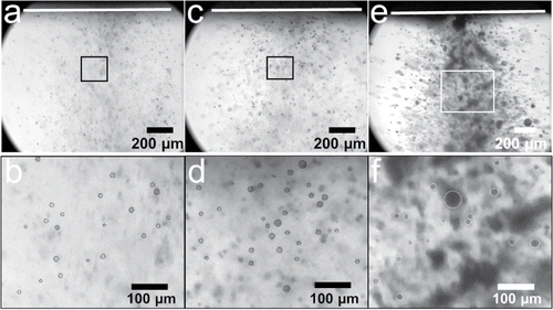
Typical images of aerosols obtained with the ultra-high speed video camera are shown in for ΔP = 200 kPa, Po = 4.2 MPa, and Q = 0.3 mL/min ( and ), Q = 1 mL/min ( and ), and Q = 5 mL/min ( and ). The images correspond to a single frame out of hundred recorded. , , and are the magnified rectangles marked in , , and , respectively. As a guide, some of the droplets are circled with a dashed line. The presented images have been processed with the ImageJ software. Qualitatively, an increase in the droplet size is observed with rising of the liquid flow rate, as would be expected for mass and momentum conservation, which is particularly clear at the higher flow rate, Q = 5 mL/min ( and ). The size increase is also accompanied with an apparent broadening of the lower and upper size limits. The ADM program processes a sequence of 102 frames to track each droplet's position, average size, and speed in every frame while subtracting the static background. Note that the ADM was developed for microfluidics applications, where droplets' images are generally neatly defined. In dense sprays; however, there is a wide range of droplet sizes coming out simultaneously. For these cases, the accuracy of the ADM program depends on the quality of the recorded video. Thus, larger droplets with a sharp perimeter have higher probability of being detected by the software. Smaller droplets without a clear edge and poor contrast with their background go through, in some cases, undetected. Nevertheless, a careful manipulation of the ADM program's features still allows to obtain useful information from FB generated sprays, at least partially. Figure S2 shows a frame of a typical FB atomization extracted from a high-speed video and the observed motions are indicated by arrows. In the image, the background, including optical artifacts and stains, has been removed with ImageJ, thus the black spots are individual droplets or groups of droplets. Although the image may appear blurry, it is the result of a processing with ImageJ to illustrate the overall fluid motions in the chamber. Along the centerline of the spray plume, at a radial distance of zero, there exists a high-speed zone which extends relatively far beyond the frame's vertical length (1.2 mm). At the periphery of the spray plume; however, a low-speed zone (dashed ovals) is created, where relatively large droplets are observed. Furthermore, between the low- and high-speed zones, there appears a motion from the periphery that accelerates droplets toward the inner part of the plume (curved, large arrows). In some videos, it is observed how droplets of relatively large size are pulled into the spray plume by this motion, from the exterior toward r = 0, and further accelerated downstream.
Figure 2. Photographs of water aerosols recorded with the ultra-high speed camera for ΔP = 200 kPa, Po = 4.2 MPa, and Q = 0.3 mL/min (a and b), Q = 1 mL/min (c and d), and Q = 5 mL/min (e and f). The white line at the top indicates the nebulizer's tip. Images (b), (d), and (f) are magnified views of the rectangles in images a, b, and c, respectively.
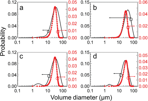
Droplet size distribution data from LSM and ADM analyses are discussed in this section. The number-based data collected with the ADM program were converted to a volume-based size distribution using a lognormal distribution function. shows volume-based droplet size distributions of aqueous aerosols generated with ΔP of 200 kPa (), 1 MPa (), and 2 MPa (), with varying Po, and low liquid flow rates, Q = 0.3 mL/min and Q = 0.5 mL/min for ADM and LSM, respectively. The red circles were obtained from analyses of high-speed videos with a frame width of 1.4 mm and height of 1.2 mm. Note that despite the difference in Q in these set of data, the variation in mean droplet diameter is expected to be less than 10% based on the model developed by Rosell-Llompart and Gañán-Calvo (Citation2008). In the four cases, with ΔP = 200 kPa, the distributions obtained with ADM (red circles) match those from the curve of LS measurements (black line). With ADM, despite the relatively low liquid throughput (0.3 mL/min), a reasonably good size distribution is obtained. For the same Q, the aerosol concentration laid below the detection limit of the LS instrument, as confirmed through many measurements where no reliable signal was obtained. The accuracy of the ADM program may be improved by using higher magnification lenses during recording, at the expense of reducing the field of view. The mean droplet diameter and geometric standard deviation recorded through LSM are summarized in . For constant ΔP (200 kPa) and Q (0.5 mL/min), there seems to be an apparent increase in mean droplet diameter from 8 µm at Po = 1.2 MPa to 10 µm at Po = 4.2 MPa, although such variation may be within the experimental error. Additionally, the standard deviation appears as though it varies slightly from 0.7 down to 0.6 for the same pressure range, thus indicating narrowing of the distribution. That is, for a constant ΔP (and also Q) the mean diameter is not expected to vary significantly. Conversely, as ΔP is increased up to 1 and 2 MPa the mean droplet diameter shifts toward smaller sizes. Such downsize is accompanied by a slight broadening of the distribution, as evidenced by a rise of the standard deviation from ∼ 0.55 to ∼0.70: a bigger ΔP obviously implies not only a larger amount of turbulent energy invested in surface generation per unit liquid volume, but also a wider range of length scales of the turbulent energy cascade.
Figure 3. Particle size distributions of water droplets obtained with the ADM program (red circles, Q = 0.3 mL/min) and with light scattering (black line, Q = 0.5 mL/min) at ΔP = 200 kPa, and Po of (a) 1.2 MPa, (b) 2.2 MPa, (c) 3.2 MPa, and (d) 4.2 MPa, (e) ΔP = 1 MPa (Po = 4 MPa), and (f) ΔP = 2 MPa (Po = 5 MPa).
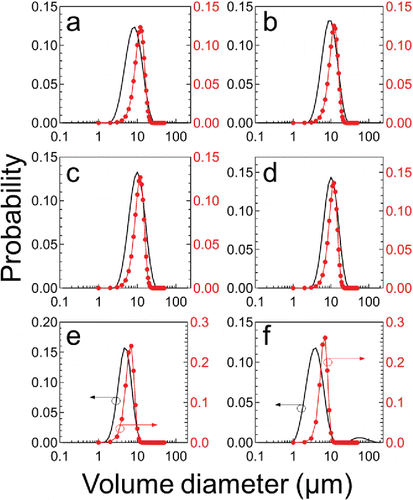
Table 1. Mean droplet diameter and standard deviation based on LS measurements.
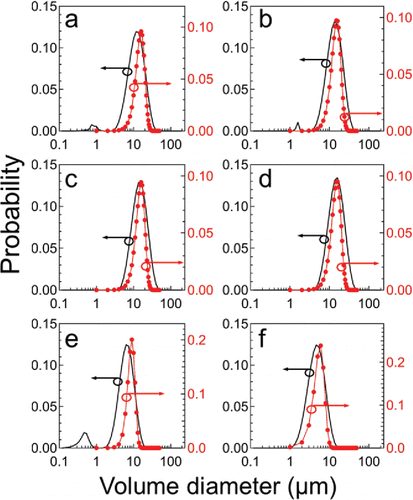
In the case of Q = 1 mL/min for ΔP = 200 kPa and varying Po, the size distributions obtained with ADM fall again under the curve of the LSM, indicating a relatively good correlation (). For these set of data, too, increasing Po from 1.2 to 4.2 MPa apparently raised the mean droplet diameter by nearly 3 µm and the distributions also undergo a slight narrowing, as indicated by a decreasing of the standard deviation (). Again, as in the previous case, the increase may be within experimental error. For ΔP of 1 and 2 MPa, the mean droplet diameter is smaller than that of ΔP = 200 kPa and the diameter reduction is also accompanied by a broadening of the distribution; as mentioned above, bigger ΔP means larger turbulent energy input, thus resulting in larger liquid surfaces (i.e., smaller droplets) with wider range of scales. Furthermore, the mean diameters are larger than those obtained with Q = 0.5 mL/min, for the same ΔP, consistently with the expected decrease of surface generated per unit volume (i.e., the inverse of the Sauter Mean Diameter) under the same energy input.
Figure 4. Particle size distributions of water droplets obtained with the ADM program (red circles) and with light scattering (black line) at Q = 1 mL/min, ΔP = 200 kPa, and Po of (a) 1.2 MPa, (b) 2.2 MPa, (c) 3.2 MPa, and (d) 4.2 MPa, (e) ΔP = 1 MPa (Po = 4 MPa), (f) ΔP = 2 MPa (Po = 5 MPa).
As Q is further increased up to 5 mL/min, for a ΔP of 200 kPa, LSM and ADM analyses match closely (). Such results may arise, partially, due to an increase in the size of the droplets, thus improving the resolution of the analyses with ADM. Note also that while LSM produces a relatively smooth curve, ADM analyses generate discrete sizes and are dependent on the counts of droplets in each frame. However, in the distributions presented herein, the data have been converted to a lognormal distribution. The mean droplet diameter shows an irregular trend for the range of Po explored in the current work. Compared to the smaller Q cases, the larger mean sizes obtained in this data set is justified by an increase in the mass of liquid supplied to the system.
Figure 5. Particle size distributions of water droplets obtained with the ADM program (red circles) and with light scattering (black line) at Q = 5 mL/min, ΔP = 200 kPa, and Po of (a) 1.2 MPa, (b) 2.2 MPa, (c) 3.2 MPa, and (d) 4.2 MPa.
Furthermore, the droplets' speed was investigated with ADM. The average droplet speed distributions of the cases discussed above are shown in – for Q = 0.3 mL/min, Q = 1 mL/min, and Q = 5 mL/min, respectively. The speed has been made non-dimensional by the theoretical speed, Vth, of the gas exiting through the geometrical gap with dimension H, the so-called lateral cylindrical passageway (LCP) (Gañán-Calvo Citation2005), as depicted in . Vth was calculated using Equation (Equation1[1]
[1] ) below and assuming adiabatic expansion of the gas as it exits to the pressurized environment, and the values are listed in :
[1]
[1] where M is the Mach number, γ is the adiabatic expansion coefficient, R is the ideal gas constant, m is the molecular weight of the gas, and T is the absolute temperature of the gas at the exit. Since M = 1 for a convergent discharge geometry like the one considered here, then
, where
is the ambient temperature. For the cases with low Po and low/medium Q values ( and and and ), the distribution depicts a nearly flat profile along the centerline of the spray, that is, at a radial distance of zero, and the speeds in that region are much smaller than Vth.
Figure 6. Average speed profile of water droplets obtained with the ADM at Q = 0.3 mL/min and ΔP = 200 kPa, and Po of (a) 1.2 MPa, (b) 2.2 MPa, (c) 3.2 MPa, and (d) 4.2 MPa, (e) ΔP = 1 MPa (Po = 4 MPa), (f) ΔP = 2 MPa (Po = 5 MPa).
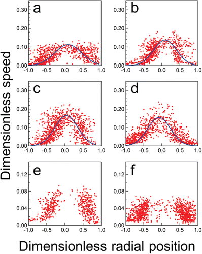
Figure 7. Average speed profile of water droplets obtained with the ADM at Q = 1 mL/min and ΔP = 200 kPa, and Po of (a) 1.2 MPa, (b) 2.2 MPa, (c) 3.2 MPa, and (d) 4.2 MPa, (e) ΔP = 1 MPa (Po = 4 MPa), (f) ΔP = 2 MPa (Po = 5 MPa).
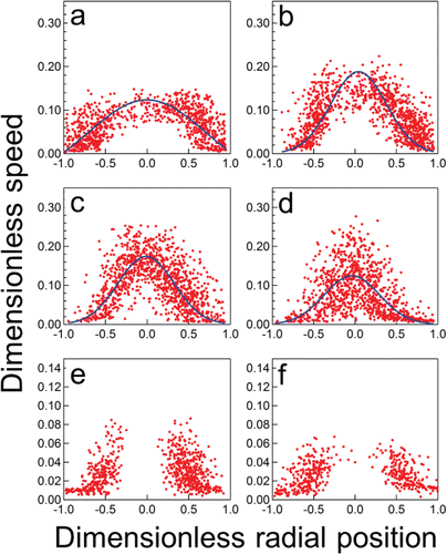
Figure 8. Average speed profile of water droplets obtained with the ADM at Q = 5 mL/min and ΔP = 200 kPa, and Po of (a) 1.2 MPa, (b) 2.2 MPa, (c) 3.2 MPa, and (d) 4.2 MPa.
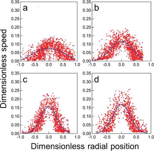
As Po is increased, still for low/medium Q values ( and ), the flat front disappears and instead the distributions become sharper, with the maximum speed being achieved at a radial distance of r = 0. In those cases, the maximum measured mean speed reaches nearly the 20% of Vth. Further increase of Po up to 4.2 MPa, for the same flow rates ( and ), results in speed distributions with a marked sharp profile, where the maximum speed was attained at a radial distance of zero, that is, along the centerline of the spray plume, and with values of the order of 30% of the theoretical speed. For the cases with ΔP ≥ 1 MPa and low/medium values of Q ( and and and ), the distributions are significantly different to the previous cases. It appears as if the droplets, particularly, in the central region (r = 0) of the plume, move faster than the recording threshold speed of the video camera. Indeed, the maximum speed values detected with the ADM program do not reach the 10% of the theoretical speed. In the case of the highest Q (5 mL/min), the speed distributions clearly show a sharp profile (), even for the lowest Po case, which at lower flow rates showed a flat profile.
However, the maximum measured speeds still do not reach their theoretical values. Even when Po is increased >3.2 MPa, droplets in the plume at a radial distance of zero reach approximately 25% of Vth. The speed distributions (for ΔP = 200 kPa) have been fitted with Gaussian profiles (blue line) and it appears they correlate well, except for the data set where the speed profile is nearly flat (). The speed data obtained with ADM agrees qualitatively with FB results reported by other authors (Jiang and Agrawal Citation2015; Fisher et al. Citation2017; and Niguse and Agrawal Citation2017). They as well observe a maximum at the radial distance of zero. Fisher et al. (Citation2017) also report a sharp speed profile in the region near the spray emission point and it transitions to a flat profile at an axial position further away from the emission point (100 mm).
Gañán-Calvo (Citation2005) derived a scaling law for FB at ambient pressure (Pi) in terms of Weber (We) and Ohnesorge (Oh) numbers, and the gas-to-liquid mass ratio (GLR) in the atomizer. The We have been calculated with ρgUg2D(2σ)−1 and using the gas density (ρg) and velocity (Ug = Vth) at the exit of the LCP assuming adiabatic expansion of the gas. Surface tension values, σ, of water and ethanol were calculated as a function of the temperature at the exit of the LCP. The Ohnesorge number, Oh, is given by µ(ρlσD)−1/2, where µ and ρl are the liquid viscosity and density, respectively. The expression of Gañán-Calvo (Citation2005), Equation (Equation2[2]
[2] ), relates a measured mass median diameter (MMD), through a dimensionless parameter δ (= MMD/D), with the dimensionless quantities: We, Oh, and GLR.
[2]
[2]
In , we have plotted a similar relationship using a dimensionless parameter, δ*. That is, the blue circle data points were obtained with = MMDexp/D, where the MMDexp was calculated from our experimental
data with
and using the geometric standard deviation of the distribution,
. Here, is the volume-based mean droplet diameter. In the case of the green squares,
was calculated by introducing a (
/D)1/3 factor to the expression of Gañán-Calvo (Citation2005), that is,
. In , the black, solid line shows the model of Gañán-Calvo (Citation2005) for FB at relatively low pressure conditions. The data points calculated using
(MMDexp) spread above the FB model and they appear to be independent of the Mach number. Although the data follow the general trend of the FB model, there is a relatively large dispersion around a power fit (black, dashed line), which results in
. Conversely, data points calculated with
are aligned below the FB model and the data collapse is improved, compared to the
case, resulting in a power fit (black, dotted line) of
. In this data set, too, the trend appears to be independent of the Mach number.
Figure 9. (a) as function of GLR, where
is given by MMD/D (circles) and
(squares). The black solid line depicts the model of Gañán-Calvo (Citation2005). Crossed circles and squares are data of ethanol. (b) Dimensionless mean diameter,
, as a function of the dimensionless liquid flow rate, (Q/Qo). The closed circles indicate data of ethanol. The dashed, blue line shows a power fitting
. The black, solid line depicts the lowest limit of the FB model and the green, dotted line shows the upper boundary delimited by the Rayleigh + Flow Focusing regime. (c)
as a function of
. The green, crossed circles are data of ethanol. (d)
plotted as a function of
. The closed circles correspond to data of ethanol.
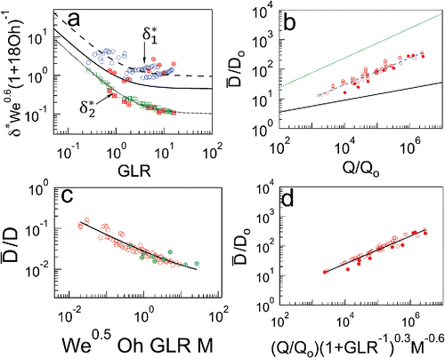
Another scaling relationship is established by the dimensionless mean droplet diameter /Do as function of the dimensionless liquid flow rate Q/Qo, which is plotted in , where Do = σ/ΔP and Qo = (σ4/ρlΔP3)1/2 are of the order of the minimum attainable diameter and flow rate, respectively (Rosell-Llompart and Gañán-Calvo Citation2008). The blue, closed circles correspond to data of ethanol. In the same graph, the lowest limit of a FB model, at relatively low pressure, by Rosell-Llompart and Gañán-Calvo (Citation2008) is also plotted (black solid line) along with an upper boundary set by the so-called Rayleigh + Flow Focusing regime (green, dotted line), in which a liquid micro jet breaks up by growth of axisymmetric waves at a critical hydrodynamic We. Our data fall between both limits, similarly as reported by Rosell-Llompart and Gañán-Calvo (Citation2008), thus indicating the occurrence of the flow blurring phenomenon. A fitting of the data gives
. Note the exponent of approximately 2/5, for the pressure range measured in this work, which is 1/5 for the lower limit as established by the FB model (Rosell-Llompart and Gañán-Calvo Citation2008). In we have plotted a dimensionless droplet diameter (
/D) as a function of We, Oh, the GLR, and the Mach number, which are parameters strongly affecting the described FB process. A relatively good collapse of the data is observed independently of the liquids' properties and the pressure conditions (subsonic or supersonic). The data are fitted by the expression
. In , /Do is depicted as function of Q/Qo, GLR, and M. In this case, a slightly improved data collapse is observed with respect to , in which
/Do is a sole function Q/Qo. A power fit results in an exponent of approximately ∼1/2 for our experimental data. The proposed scaling expressions relate
and MMD to the main parameters of FB atomization in high pressure environments. They provide a guideline for the analyses of droplet sizes in such conditions.
Conclusions
Aqueous and ethanol aerosols produced by a FB® nebulizer under high pressure conditions have been investigated both with direct visualization, using an ultra-high-speed video camera coupled with an in-house developed program, and with light scattering measurements. The ADM program, typically used for analyses of micro-fluidic systems, was successfully applied to aerosols with relatively high throughput and turbulent motions. Droplet size distributions obtained with the ADM program are comparable to those obtained with LSM. Particularly, a good fit is found at the highest liquid flow rate, where the droplets are larger and can be readily detected during image processing. With LS instrument, mean droplet diameters in the range 8–26 µm were obtained with a ΔP = 200 kPa and liquid flow rates in the range 0.3–5 mL/min. Increasing ΔP up to 1 and 2 MPa caused a significant reduction of the mean droplet diameter. As Po is increased (constant ΔP = 200 kPa), the mean droplet speed shifts from a relatively flat profile at low Q to a sharp distribution at medium Q. At high liquid flow rate; however, the mean droplet speed approaches a Gaussian distribution, even for low Po values. Fitting of a number of FB experiments (ϕ = 1/6) for ΔP in the range 200 kPa–3 MPa, and Po as low as 500 kPa, result in (/Do) = 0.47 (Q/Qo)0.45. The experimental mass median diameter obtained at high-pressure conditions appears to have a similar trend as the FB scaling law of Gañán-Calvo (Citation2005) for atmospheric discharge pressure (Pi). Based on the same scaling law, a modified parameter in terms of (
/D)1/3 was proposed to fit the data as a function of the gas-to-liquid mass ratio. In addition, other scaling relationships for the mean droplet diameter of sprays produced by FB at relatively high pressure conditions were established, which incorporate the effect of the external pressure through the Mach number. The approach presented in this study may be a guideline for implementation of FB in high-pressure applications, for instance, in combustion technology.
UAST_1390207_Supplemental_data.pdf
Download PDF (481.4 KB)Additional information
Funding
References
- Aguirre, M. A., Kovachev, N., Almagro, B., Hidalgo, M., and Canals, A. (2010). Compensation for Matrix Effects on ICP-OES by On-line Calibration Methods Using a New Multi-Nebulizer Based on Flow Blurring® Technology. J. Anal. At. Spectrom., 25:1724–1732.
- Bedford, F., Rutland, C., Dittrich, P., Raab, A., and Wirbeleit, F. (2000). Effects of Direct Water Injection on DI Diesel Engine Combustion. SAE 2000-01-2938.
- Chong, Z. Z., Tor, S. B., Gañán-Calvo, A. M., Chong, Z. J., Loh, N. H., and Nguyen, N. T. (2016). Automated Droplet Measurement (ADM): An Enhanced Video Processing Software for Rapid Droplet Measurements. Microfluid. Nanofluid., 20:66.
- Fisher, B. T., Weismiller, M. R., Tuttle, S. G., and Hinnant, K. M. (2017). Effects of Fluid Properties on Spray Characteristics of a Flow-Blurring Atomizer. In ASME. Turbo Expo: Power for Land, Sea, and Air, Volume 4A: Combustion, Fuels and Emissions (11 pp). Charlotte, North Carolina, USA. doi:10.1115/GT2017-63135.
- Gañán-Calvo, A. M. (1998). Generation of Steady Liquid Microthreads and Micron-Sized Monodisperse Sprays in Gas Streams. Phys. Rev. Lett., 80(2):285–288.
- Gañán-Calvo, A. M. (2005). Enhanced Liquid Atomization: From Flow-Focusing to Flow-Blurring. Appl. Phys Lett., 86:214101.
- Gañán-Calvo, A. M. (2008). Procedure and Device for the Micro-Mixing of Fluids Through Reflux Cell. Patent US20080271350 A1.
- Hiroyasu, H. and Kadota, T. (1976). Fuel Droplet Size Distribution in Diesel Combustion Chamber. Bull. JMSE, 19:1064–1072.
- Johansen, G. A., Hampel, U., and Hjertaker, B. T. (2010). Flow Imaging by High Speed Transmission Tomography. Appl. Radiat. Isot., 68:518–524.
- Jiang, L. and Agrawal, A. K. (2015). Spray Features in the Near Field of a Flow-Blurring Injector Investigated by High-Speed Visualization and Time-Resolved PIV. Exp. Fluids, 56:103.
- Kovachev, N., Almagro, B., Aguirre, M. A., Hidalgo, M., Gañán-Calvo, A. M., and Canals, A. (2009). Development and Characterization of a Flow Focusing Multi Nebulization System for Sample Introduction in ICP-Based Spectrometric Techniques. J. Anal. At. Spectrom., 24:1213–1221.
- Modesto-López, L. B. and Gañán-Calvo, A. M. (2017, August-September). Liquid Atomization by Flow Blurring® (FB) in a High-Pressure Environment for Combustion Applications. Paper presented at the European Aerosol Conference 2017, Zurich, Germany.
- Niguse, Y. G. and Agrawal, A. K. (2017). Twin-Fluid Atomized Spray Combustion of Straight Vegetable Oil at Elevated Pressures. In ASME. Turbo Expo: Power for Land, Sea, and Air, Volume 3: Coal, Biomass and Alternative Fuels; Cycle Innovations; Electric Power; Industrial and Cogeneration Applications; Organic Rankine Cycle Power Systems (11 pp). Charlotte, North Carolina, USA. doi:10.1115/GT2017-65191.
- Pereira, C. D., Aguirre, M. A., Nóbrega, J. A., Hidalgo, M., and Canals, A. (2014). Aerosol Generation of As and Se Hydrides Using a New Flow Blurring® Multiple Nebulizer for Sample Introduction in Inductively Coupled Plasma Optical Emission Spectrometry. Microchem. J., 1112:82–86.
- Rosell-Llompart, J. and Gañán-Calvo, A. M. (2008). Turbulence in Pneumatic Flow Focusing and Flow Blurring Regimes. Phys. Rev. E, 77:036321.
- Sahin, Z., Tuti, M., and Durgun, O. (2014). Experimental Investigation of the Effects of Water Adding to the Intake Air on the Engine Performance and Exhaust Emissions in a DI Automotive Diesel Engine. Fuel, 115:884–895.
- Schneider, C. A., Rasband, W. S., and Eliceiri, K. W. (2012). NIH Image to ImageJ: 25 Years of Image Analysis. Nat. Methods, 9(7):671–675.
- Simmons, B. and Agrawal, K. A. (2012). Flow Blurring Atomization for Low-Emission Combustion of Liquid Biofuels. Combust. Sci. Technol., 184:660–675.
- Wittig, S., Klausmann, W., Noll, B., and Himmelsbach, J. (1988). Evaporation of Fuel Droplets in Turbulent Combustor Flow. In ASME 1988 International Gas Turbine and Aeroengine Congress and Exposition: Vol 3. Coal, Biomass and Alternative Fuels; Combustion and Fuels; Oil and Gas Applications; Cycle Innovations (6 pp). Amsterdam, The Netherlands. doi:10.1115/88-GT-107.
