ABSTRACT
Direct ultraviolet (UV) photoionization enables electrical charging of aerosol nanoparticles without relying on the collision of particles and ions. In this work, a low-strength electric field is applied during particle photoionization to capture charge as it is photoemitted from the particles in continuous flow, yielding a novel electrical current measurement. As in conventional photocharging-based measurement devices, a distinct electrical current from the remaining photocharged particles is also measured downstream. The two distinct measured currents are proportional to the total photoelectrically active area of the particles. A three-dimensional numerical model for particle and ion (dis)charging and transport is evaluated by comparing simulations of integrated electric currents with those from charged soot particles and ions in an experimental photoionization chamber. The model and experiment show good quantitative agreement for a single empirical constant, KcI, over a range of particle sizes and concentrations providing confidence in the theoretical equations and numerical method used.
Copyright © 2018 American Association for Aerosol Research
EDITOR:
1. Introduction
Direct ultraviolet (UV) photoionization is a method of electrically charging aerosol nanoparticles distinct from the conventional diffusion charging mechanism which relies on the collision of particles and ions. In direct particle photoionization, photons of sufficient energy are absorbed, causing particles to emit electrons, thus leaving the particles positively charged. Photoionization can yield significantly higher charging efficiencies than diffusion-based methods for some nanoparticle materials over a range of particle sizes in the free molecular regime (Jung et al. Citation1988; Mohr et al. Citation1996; Li and Chen Citation2011). The increased charging, material dependency, and collision-free charging mechanism provide opportunities for sensing (Niessner Citation1986; Burtscher et al. Citation1988; Matter et al. Citation1995), capture (Jiang et al. Citation2007b), and control of aerosol nanoparticles.
Particle photocharging theory was developed to study the enhanced charging efficiency of nanoparticles over flat surfaces (Cardona and Ley Citation1978; Schmidt-Ott et al. Citation1980; Schmidt-Ott and Federer Citation1981; Wood Citation1981). More recent studies have evaluated photocharging theory by measuring the capture efficiency of photocharged particles in a high voltage electrostatic precipitator (Jiang et al. Citation2007a,Citationb; Hontañón and Kruis Citation2008; Li and Chen Citation2011). The equation for photoionization yield generally includes an empirical constant which has been used as a fitting parameter for changes in particle size, light intensity, or flow rate (Jiang et al. Citation2007b; Hontañón and Kruis Citation2008). Li and Chen (Citation2011) investigated the effect of UV light intensity on the photoionization of silver nanoparticles for a range of light intensities. They showed no size dependence for the photoemission constant of 7–30 nm silver particles, which is in agreement with photocharging theory and calculations, yet in contrast with previous research (Jiang et al. Citation2007b; Hontañón and Kruis Citation2008). Further work on modeling and experiments of particle photoionization included the role of particle size, light intensity, residence time, and diffusion losses (Mohr and Burtscher Citation1997; Maisels et al. Citation2002, Citation2003; Van der Zwaag et al. Citation2008). More recently, we have implemented physical models for photoionization and charge motion into a multidimensional numerical model to demonstrate how photoionized particles and ions are transported in convective flows subjected to an electric field (Nishida et al. Citation2017).
Photoemission yield is a linear function of particle active surface which is defined as being proportional to the inverse of particle mobility (Schmidt-Ott et al. Citation1990; Keller et al. Citation2001). Experimental results show photoelectric yield to be a linear function of inverse electrical mobility for carbon agglomerates (Burtscher Citation1992), fractal-like silver agglomerates (Schmidt-Ott et al. Citation1990) (20 < dm < 100 nm, dfm = 2.26) (Schmidt-Ott Citation1988; Wang and Sorensen Citation1999), diesel soot (Burtscher et al. Citation1998), and recrystallized Ag and Au (Keller et al. Citation2001), for particle mobilities largely in the free-molecular regime (20 < d < 100 nm). Photoemission yield is found to be a linear function of total particle (mobility) surface area, a nearly equivalent measurement to total active surface, for polyaromatic hydrocarbon (PAH) coated graphite aerosols (measured by diffusion battery) (Niessner Citation1986), denuded diesel exhaust particles at five representative engine modes (measured by scanning mobility particle sizer, SMPS) (Kittelson et al. Citation2005), and sintered spheres and fractal-like agglomerates of Ag (SMPS) (Zhou et al. Citation2013). Measurements of the aerosol total active surface area are of interest for emissions, environmental, or exposure monitoring, particularly for materials such as elemental carbon and diesel soot, however, the dependence of particle material and morphology on photoemission must be understood. For that reason, photocharging theory (Cardona and Ley Citation1978; Schmidt-Ott et al. Citation1980; Wood Citation1981; Schmidt-Ott and Federer Citation1981) must be adequately validated using combined modeling and experimental techniques (Mohr and Burtscher Citation1997; Maisels et al. Citation2002, Citation2003; Jiang et al. Citation2007a,Citationb; Hontañón and Kruis Citation2008; Van der Zwaag et al. Citation2008; Li and Chen Citation2011; Nishida et al. Citation2017).
In this work, we use the computational fluid dynamics (CFD) model in Nishida et al. (Citation2017) and detailed experiments to demonstrate how photoionization and an electric field can be employed to detect and measure particles in a continuous flow. An experimental photoionization chamber is outfitted with a low-strength electric field (of order 10 V cm− 1) in order to capture ions, reduce recombination, and increase the particle charge state in a continuous flow of aerosol nanoparticles. The electric field enables measurement of two distinct currents: the first from ions captured in the photoionization chamber, and the second from the remaining charged particles. Experimental data are obtained for photoionization of a range of soot particle sizes and concentrations in continuous flow. Measured electrical currents are compared with those calculated from a 3D computational fluid dynamics model which includes equations for particle and ion flow, photocharging, recombination, diffusional wall losses, and electric field transport. A single empirical constant and particle work function are used to account for photoionization. The novel approach of using an electric field to yield two distinct electrical current measurements is demonstrated to be useful for direct measurements of total photoelectrically active surface area of a known aerosol material.
2. Method
2.1. Theory
In direct particle photoionization, absorbed UV photons of sufficient energy cause particles to emit electrons, generating positively charged particles. The emitted electrons quickly collide with surrounding gas molecules, creating negatively charged gaseous ions. The electrostatic fields generated by the positively charged particles in turn create higher energy barriers for further release of photoelectrons. The probability (or combination coefficient) of photocharging spherical particles from charge level q to q + 1, αq → q + 1, is given by (Cardona and Ley Citation1978; Maisels et al. Citation2002)[1] where I is the radiative energy flux, hν is the specific photon energy, and πd2p/4 is the photoelectrically active area of a particle with diameter, dp. The proportionality constant, Kc, is material dependent and empirically determined. The value of the exponent m has been determined as around 2 for metals and a few non-metals (Schmidt-Ott and Federer Citation1981; Müller et al. Citation1988; Jiang et al. Citation2007a). A positive emission probability means that hν > Φ where the particle surface work function, Φ, increases with each electron emission according to
[2] for the work function of a flat surface of the same material, Φ∞, and elementary electron potential, Ve (Cardona and Ley Citation1978; Maisels et al. Citation2002). The range of applicability to different materials is limited to those with a high-enough proportionality constant, Kc, for detection and low enough work function, Φ∞, for photo-emission from available UV sources. Wavelengths of light lower than about 190 nm at high intensity can directly ionize gas molecules or lead to unwanted photochemical reactions (Matter et al. Citation1995).
The rate of ion generation via photoionization is moderated by the rate at which charged particles recombine by collision at a rate β:[3]
[4] according to the method of Hoppel and Frick (Citation1986) and Fuchs (Citation1963) which includes electrostatic and diffusive forces, represented by the first and the second terms in the denominator, respectively. The rate of collision is proportional to the collisional cross-sectional area πδ2, where δ is the limiting sphere radius, the mean molecular velocity c, and ion-particle collision probability, αC, which depends on charge and distance (Reischl et al. Citation1996). The electrostatic potential, ϕ, depends on particle material, diameter, and distance from the center of the particle, r, where K = 1 for a perfectly conducting particle. The number and polarity of particle charges, i, is positive if the ion and particle are of the same polarity. Recombination of an ion with a charged particle assumes the ion transfers charge to the particle, leading to a sink term in the conservation equations for both particles and ions. More detail on the charging and recombination equations can be found in Nishida et al. (Citation2017).
2.2. Operating method
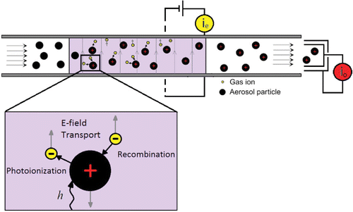
The positively charged particles and negatively charged ions are generated in a continuous flow chamber, where they are allowed to partly recombine, while surrounded by an applied electric field (). The net ionic flux to the electrode surfaces creates a current which can be detected at different locations. Negatively charged ions are transported to the positive electrode, while positively charged particles migrate to the negative electrode, both contributing to electrode current, ie, which can be measured by an external circuit. Negatively charged ions are gaseous and thus have electric mobilities of around 100 times greater than positively particles in the size range of interest (10–300 nm), so in general the corresponding negative ion flux is much higher than that created by the motion of positively charged particles. The remaining positively charged particles and negatively charged ions are transported through the chamber outlet to yield an outlet current, io. The outlet current, io, and the chamber electrode current, ie, are each directly related to the rate and efficiency of particle charging, so they contain information about the particle number and available charging area. Importantly, all measurements are conducted in steady-state, so there is no effect of induced current due to image charges on the electrode current, ie.
Figure 1. Diagram of photoionization chamber. Highly mobile ions and a fraction of the charged particles are transported by the electric field and captured, yielding an electrode current, ie. The remaining charged particles and ions are captured at the outlet yielding outlet current, io.
EquationEquation (1)[1] shows that the probability of photocharging depends directly on the particle area, which is proportional to d2p. The total charged particle flow is expected to therefore be proportional to the integral of the photoelectrically active area of all particles,
[5] where f(dp) is the probability distribution function of the particle size, and Nd is particle concentration as a function of particle size. Owing to charge conservation, the total captured currents ie and io indicated in must be identical, and proportional to the photoelectrically active surface area. However, given the different rate of recombination, transport, and capture of particles and ions through the electric field, the measurable currents from the photocharging process are in effect different functions of concentration, N, and particle diameter, dp, as described in the following sections. This allows for the potential for estimating particle diameter and number independently.
2.3. 3D computational model
Equations for 3D, steady-state advection/diffusion, photoionization, recombination, and electric field transport of particles and ions are solved in three dimensions using computational fluid dynamics. The model includes photoionization and recombination theory as verified by comparison with analytical and 0D numerical models (Hoppel and Frick Citation1986; Maisels et al. Citation2002, Citation2003) presented in Nishida et al. (Citation2017).
The velocity and pressure fields are solved using the incompressible, steady-state Navier–Stokes equations for the carrier gas. The velocity field, , assumes convection of the carrier gas is independent of particle dynamics and electrical effects. Conservation equations for particle concentrations with a given charge q, Nq, for a monosized particle distribution for particle charges between qmin and qmax, and ions of single negative charge, n− 1,
[6a]
[6b] for particle diffusivity, Dp, electrical mobility, Zq, and electric field,
, and particle charging and recombination coefficients α and β given in EquationEquations (1)
[1] and Equation(3)
[3] , respectively. The concentration of particles with charge q is changed by the net rate of particles acquiring or losing an extra charge due to photoemission and ion/particle recombination. The concentration of ions of a single negative charge is changed by the net rate of electron photoemission and ion/particle recombination at all particle charge states. An electric field is applied to influence the trajectory of particles and ions between two electrodes during photoionization. A Laplacian equation is solved for an applied voltage, V, at the electrodes to generate a potential field. The local electric field,
, is the gradient of the potential field according to
[7] where it is assumed that the electric field distribution is independent of the space charge. The flux of particles and ions transported to and captured at the electrode boundaries are integrated over the boundary area to yield an electrode current, ie. The flux of particles and ions convected through the outlet boundary are integrated over the outlet area to yield the charged particle current, io.
2.3.1. Geometry and mesh
The geometry consists of a cylinder containing two concentric electrodes used for electric field transport of ions and particles. The first electrode is a cylinder of 25 mm diameter and 200 mm length. The second electrode is a concentrically located rod of 1.5 mm diameter. An UV light source is placed at the upstream end of the system. The computational mesh comprises a 1/8th section of the tube due to the axisymmetric nature of the solution.
The governing equations are converted to steady-state linear algebraic equations and solved using the CFD package, OpenFOAM v.4. After a study of grid independence, the computational mesh consists of 230,400 cells graded near walls where the largest concentration gradients occur. The minimum charge level of Equation (6) is set to −5 charges per particle such that the concentrations of all neutral and negatively charged particles in this system are calculated. Solution time is a function of the theoretical maximum charge due to photoionization which determines the number of simultaneous concentration equations considered. For a maximum of 14 charges per particle, a solution is computed in 11.5 min on (Intel® CoreTM i7 3.40 GHz) with 16 GB of RAM running on openSUSE 13.1. Parallel processing can readily be incorporated if necessary.
2.3.2. Properties and operating conditions
The particle flow comprises neutrally charged, monodisperse particles in air at NTP conditions. A uniform velocity profile is prescribed at the inlet, no-slip at the walls, and zero gradient at the outlet. Constant air density, viscosity, and ion diffusivity, Di, are assumed. A fixed, neutral concentration of monodisperse particles is prescribed at the inlet, zero concentration at the electrode walls, and zero gradient at the outlet. Monodisperse particles are prescribed in the model as a first-order approximation of the polydisperse distributions produced with the experimental set-up. Modeling the effect of particle polydispersity on the electric current measured from particle photoionization requires source terms for each particle size and charge level and will be considered in future work.
The particle diffusion coefficient and electrical mobility are functions of particle diameter using mechanical mobility and Cunningham slip correction factors for air at NTP as described in Kulkarni et al. (Citation2011). Collision rates, β, are generated using ion properties from Wiedensohler (Citation1988) and EquationEquation (3)[3] .
The product of light intensity I and a constant Kc is adjusted only once to match experimental results, as summarized in along with the remaining operating conditions which correspond to the experiment. The light intensity decreases with the inverse square law in the flow direction and the product KcI is fixed at the inlet, 2 cm from the light source. The particle work function, Φ∞, for carbon particles is extracted from Michaelson (Citation1977).
Table 1. Model parameters and operating conditions.
2.4. Experimental method
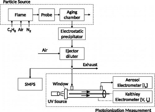
The experimental apparatus used is shown in . Stable, carbonaceous soot particles were produced by propane (65–105 std cm3 min− 1), air (1.2 std L min− 1), and N2 (3 std L min− 1) in a co-flow inverse diffusion flame followed by an ageing chamber as described in Section 2.1 of Stettler et al. (Citation2013). An electrostatic precipitator operated at 9 kV captured particles with any residual charge from the combustion process, confirmed using an aerosol electrometer (Model 3068B, TSI Inc., Shoreview, MN, USA). An ejector diluter with filtered compressed air provided a vacuum to draw the sample through the aging chamber and electrostatic precipitator. The concentration was varied by changing the diameter of the critical orifice in the diluter and the flow rate of dilution air. The particle size was varied by changing the flow rate of propane into the flame. Higher flow rates of propane yielded larger particle sizes. The number-weighted particle mobility diameter distribution was measured with a Scanning Mobility Particle Sizer (SMPS; TSI Inc.: 3080 Electrostatic Classifier, 3081 Differential Mobility Analyzer [DMA], 3025 Condensation Particle Counter [CPC]). The particle mobility diameter is referred to as particle diameter, dp, in this work. Stainless steel and conductive silicone tubing were used to minimize particle losses in the sampling lines.
2.4.1. Photoionization chamber
The experimental photoionization chamber provides a volume in which aerosol particles are irradiated with UV light and subject to an electric field between two electrodes while in continuous flow. The sample aerosol flows from a sample inlet at the side of a cylindrical chamber, through the volume between the two electrodes, and through a sample outlet at the side of the chamber as seen in . The first electrode is a 200 mm long aluminum cylinder of 25 mm diameter. A concentrically located silver steel rod (functioning as the second electrode) of 200 mm in length and 1.5 mm in diameter is mounted at the end of the photoionization chamber nearest the outlet, extending co-axially along the entire length of the photoionization chamber and electrically isolated with PTFE. An UV-extended fused silica optical window of 25 mm diameter and 3 mm thickness makes up one circular side of the cylindrical chamber. A 3 W UV lamp (Model Mini3W-52ozon, Dinies Technologies GmbH, Germany) is located externally, 20 mm from the window. The UV source and window are located nearest the sample inlet such that the flow direction is away from the light source. The lamp outputs narrow lines of ultraviolet light with wavelengths of 185 nm and 254 nm. A high-pass UV filter was used to demonstrate that the 254 nm line yielded negligible photoelectric emission, therefore the 185 nm light was considered the dominant for particle photo-emission. A voltage is applied between the electrodes in series with the electrometer current measurement, both using a Keithley electrometer (Model 6517B, Keithley Instruments Inc., Cleveland, OH, USA). The photoionization chamber is enclosed in an electrically isolated, aluminium box which acts as a Faraday cage and is grounded with the electrometer triaxial measurement cable. The electrometer provides electrode current, ie, with an accuracy of ±3 fA. However, electrical noise from other sources increases the signal error. Flow through the photoionization chamber was sampled from the ejector diluter exhaust line by the aerosol electrometer (1.5 std L min− 1). The aerosol electrometer measures outlet current, io, using a particle filter in a Faraday cup electrometer with a noise level less than 1 fA at 1 s averaging time.
3. Results
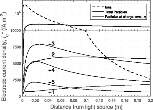
Initially neutral particles flow in the direction perpendicular to the electric field between two electrodes and away from the UV light source. The particles are photoionized, yielding ions and charged particles, which are simultaneously transported to the electrodes and measured as electrical current. Modeling results for the components of the electrode current density, i′′e, as a function of distance from the light source are shown in . The electrode current arises largely from capture of negatively charged ions nearest the light source; the rate of capture of ions decreases with distance from the light source. A much smaller fraction of the current is contributed by particles at each charge level as the flow proceeds away from the light source. The particles are photoionized to gain +1 charges which are further ionized to +2 charges and so on. The positively charged particles are captured at the electrode as the flow moves away from the light source, also contributing to the electrode current, ie. The rate of capture depends on the charge level and particle transport in the electric field. Although particles of higher charge levels such as +4 and +5 charges are more likely to be captured due to their higher electrical mobility compared to particles with +2 or +3 charges, their concentrations are lower, as there is insufficient irradiation time or light intensity to reach the higher charge levels.
Figure 3. Contributions to electrode current density, i′′e, as a function of distance from the light source for ions, particles from charge level, q = 1 → 5, and the sum total of all charged particles (dp = 80 nm, N = 105 cm− 3) at an applied voltage 25 V (20 V cm− 1). The y-axis scale changes to log scale at 1 × 10⁴ fA m− 2.
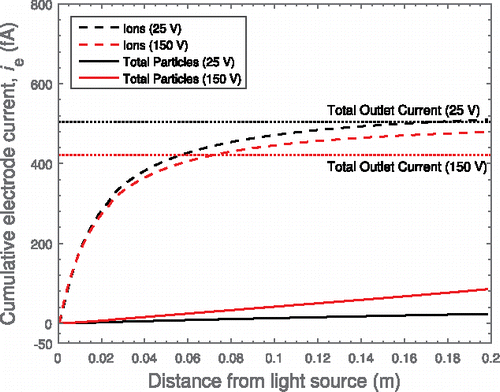
The components of the integrated electrode current are shown as a function of distance from the light source along the electrodes in for applied voltages of 25 V (20 V cm− 1) and 150 V (120 V cm− 1). As ions are captured at the electrode near the light source, the total current increases to nearly its maximum value in the first half of the chamber. The capture of particles occurs further along the chamber after sufficient time for the electric field to transport the particles to an electrode. In the 150 V (120 V cm− 1) case, the contribution to electrode current from particle capture is significantly higher than the 25 V (20 V cm− 1). The captured particles in the 150 V (120 V cm− 1) case cannot contribute to the outlet current io, and therefore reduce the total outlet current. In the 25 V (20 V cm− 1) case, the electrode current, ie, arises largely due to the cross transport of negative ions, whereas the outlet current, io, has equal magnitude and opposite sign, largely due to positively charged particles. After testing a range of electric field strengths over 0–150 V cm− 1 (6 points logarithmically spaced, not shown) for the given flow rates and particle sizes, the field level corresponding to 25 V (20 V cm− 1) is nearly optimum to yield maximum outlet current, io, and directly measure the total effect of particle photoionization. Applied voltages lower than ≈10 V (8 V cm− 1) provide insufficient ion capture, therefore allow more particle–ion recombination and reduce the electrical current at the outlet, io. For applied voltages higher than ≈25 V (20 V cm− 1), charged particle capture becomes significant as demonstrated by the analysis for 150 V (120 V cm− 1). Further discussion of the effect of electric field strength on output electrical current can be found in Nishida et al. (Citation2017). For particle sizes smaller than 80 nm diameter, the particle capture at the electrode becomes more significant, and can affect the electrode current, as discussed below.
Figure 4. Contributions to total cumulative current at the electrode, ie, as a function of distance from the light source for ions and particles (dp = 80 nm, N = 105 cm− 3) at applied voltages of 25 V (20 V cm− 1) and 150 V (120 V cm− 1).
3.1. Photoelectrically active surface
The electrode current, ie, and outlet current, io, were measured for the photoionization of fractal-like, agglomerate soot particles (characterized in Stettler et al. Citation2013) over a range of count median (mobility) diameters, CMD (25–80 nm), and total concentrations, N (9 × 10⁴ to 1.1 × 106 cm− 3) as measured by SMPS. Numerical calculations for the geometry and operating conditions considered were performed, in which a single empirical parameter corresponding to the product, KcI, adjusted to fit the model to the experiment for a single measurement. shows how the CFD model results shown in the surface plot obtained for the outlet current compare with the measurements.
Figure 5. Outlet current, io, as a function of particle concentration and diameter for applied voltage of 25 V (20 V cm− 1) from model (colored surface) and experiment (black).
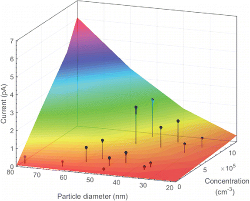
The outlet current, io, increases with both increasing particle concentration and diameter. The experimental and model results agree well for a range of particle mobility diameters (25–80 nm) (25–65 nm) with agreement up to 80 nm and concentrations (9 × 10⁴ to 1.1 × 106 cm− 3) using a single value for KcI. The results show that the mobility diameter can be used as the characteristic particle diameter, dp, in EquationEquation (1)[1] even for aggregates (Keller et al. Citation2001; Burtscher Citation2005; Zhou et al. Citation2013), agreeing with previous research for the range of soot morphology measured in this work (Stettler et al. Citation2013). For this reason, the CMD for mobility diameter is represented by dp in the remaining discussion.
The form of the dependence of current on diameter and concentration suggests a power law of the form:[8] with power fit coefficients δ and ε. Any current independent of the particle photoionization process, e.g., photoemission from housing walls is represented in the intercept coefficient, γ, and the absolute values of the remaining coefficients, ln i = ln γ + δln N + εln dp , as long as it remains constant between measurements. The relative effect of particle concentration and size on electrical current remains independent of background current, therefore the ratio ε/δ remains constant. Fit parameters for both and can be obtained from either the CFD model or directly from the experiments, and are shown in for an applied voltage of 25 V (20 V cm− 1). Once the power fit parameters in EquationEquation (8)
[8] are obtained, it is possible to obtain the expected particle concentration for a given measured diameter and current. shows the expected concentration, ⟨N⟩ = (iγ− 1d−εp)1/δ, obtained using the CFD model fit parameters of EquationEquation (8)
[8] and experimentally measured currents, io and ie, as a function of measured concentrations for an applied voltage of 25 V (20 V cm− 1). Likewise, shows the expected diameter, ⟨dp⟩ = (iγ− 1N− δ)1/ε, extracted from CFD model fit parameters of EquationEquation (8)
[8] and measured currents, and concentrations for an applied voltage of 25 V (20 V cm− 1). Experimental values of currents were measured with lognormal particle size distributions of soot featuring count median diameters 25–80 nm and geometric standard deviations between 1.54 and 1.75. These results for polydisperse measurements agree well with modeling results for monodisperse particle diameters of 40–80 nm and concentrations of 1 × 10⁴ to 1.2 × 106 cm− 3 as shown by the correlation plot in and . Monodisperse modeling results outside of this range cannot capture the current from a small concentration of larger particles that are present in polydisperse distributions. Uncertainty of the mean particle diameter and total concentration from the SMPS is 1% and 10%, respectively, consistent with published values (Mulholland et al. Citation2006; Wiedensohler et al. Citation2012). The error bars represent the standard error in io and ie current measurements which average less than 1 fA and 70 fA, respectively, for 30 s of measurements per data point at a rate of 1 s per measurement. The outlet current is more adequately shielded from electronic noise yielding more accurate measurements. Both and show the CFD model agrees well with the experiment for measurements of concentration and diameter for a single KcI fit parameter of 1.15 × 1034 J− 1m− 2s− 1.
Figure 6. Expected concentration from measured currents, io and ie, as a function of measured concentration using linear regression fit parameters from CFD model results: ⟨N⟩ = (iγ− 1d− εp)1/δ at 25 V (20 V cm− 1). The coefficients of determination are 0.97 and 0.90 for io and ie, respectively.
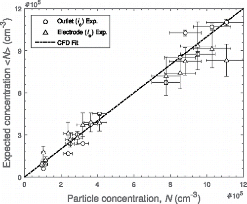
Figure 7. Expected diameter from measured currents, io and ie, as a function of measured diameter using linear regression fit parameters from CFD model results: ⟨dp⟩ = (iγ− 1N− δ)1/ε at 25 V (20 V cm− 1). The coefficients of determination are 0.88 and 0.87 for io and ie, respectively.
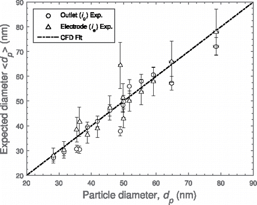
Table 2. Power-law regression fit parameters for an applied voltage of 25 V (20 V cm− 1). Uncertainty is quantified by standard error in brackets.
The independent power regression fits for experimental and CFD model results show that the outlet current, io, depends on the particle diameter according to ie∝d2.04p and ie∝d2.02p for experimental and modeling results, respectively, as shown in . The electrode current shows ie∝d1.90p and ie∝d1.92p from experimental and modeling results, respectively. The capture of a fraction of the positively charged particles as well as the negative ions at 25 V (20 V cm− 1) increases the ratio of coefficients from the value of 2 in EquationEquation (1)[1] for the outlet current and decreases it for the electrode current.
Figure 8. Expected particle diameter function from measured currents, io and ie, as a function of measured particle diameter using independent linear regression fit parameters from experiment and CFD model results: ⟨dε/δp⟩ = (iγ− 1N− δ)1/δ at 25 V (20 V cm− 1).
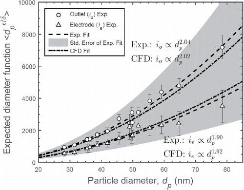
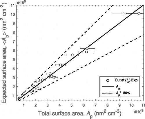
For an applied voltage of 25 V, the outlet current, io, is linearly proportional to concentration and nearly proportional to the square of diameter, i.e., io ≈ CNd2p + b. This convenient relationship gives a direct measure of total expected particle surface area, ⟨Ap⟩, defined in EquationEquation (5)[5] . The total photoelectric surface area estimates generated using io at 25 V (20 V cm− 1) are plotted as a function of the total measured surface area from the SMPS in . All the estimates generated by the photoionization device are within 30% of the SMPS values for Ap, demonstrating that under these conditions, the total photoelectrically active surface area represents the total mobility surface area as measured by SMPS.
Figure 9. Expected photoelectrically active surface area from measured current, io, as a function of total measured surface area using linear regression fit parameters from experiment: at 25 V (20 V cm− 1). (C = 2.2 × 10− 7, b = 151 fA, R2 = 0.98).
The photoemission response of soot particles from a propane flame subject to an applied electric field are analyzed in the present work. Real world aerosols contain mixtures of photo-emitting and some weakly photo-emitting materials. For example, photoemission from NaCl aerosols was below the detection limits of the present set-up. However, with further understanding, the photoionization may provide the opportunity for material selective measurements in real-world aerosols.
4. Conclusions
A novel charging and measurement method is introduced by applying an electric field to allow the direct measurement of photoemitted charge from particles captured in the electric field in continuous flow. A 3D computational fluid dynamics model is described, which includes particle photocharging, recombination, diffusional wall losses, and electric field transport. An applied voltage of 25 V (20 V cm− 1) is shown to be nearly optimum for the capture of ions at the electrode without largely capturing charged particles for the particular geometry and particle range. The model shows good agreement for measurements of two distinct electrical currents (electrode, ie, and outlet, io) with those from experimental photocharging of soot particles in a range of sizes and concentrations, for a single fitted parameter for all cases, to account for light intensity. This demonstrates that the physics of the problem is suitably captured by the model and that the method can be used to estimate material-dependent fitting parameters such as KcI. At a low applied voltage of 25 V (20 V cm− 1), for which ε/δ ≈ 2, a direct measurement of photoelectrically active surface area of soot particles becomes possible, with an accuracy of within 30% of total surface area from an SMPS (Ap). Mobility diameter is confirmed as a suitable characteristic diameter used in photoionization equations, agreeing with previous research.
Nomenclature
| Roman symbols | ||
| A | = | surface area, nm2 cm− 3 |
| c | = | mean molecular velocity, m s− 1 |
| D | = | diffusion coefficient, m2 s− 1 |
| dp | = | particle diameter, nm |
| e | = | electron charge, 1.602 × 10− 19 C |
| = | electric field, V m− 1 | |
| hν | = | light energy, eV |
| I | = | irradiation intensity, W m− 2 |
| i | = | current, A; number and polarity of particle charges |
| K | = | particle conductivity parameter |
| kB | = | Boltzmann constant, 1.38e-23 m2 kg s− 2 K− 1 |
| Kc | = | photoemission constant, J− 2 |
| m | = | empirically determined constant |
| N | = | particle concentration, cm− 3 |
| n | = | ion concentration, cm− 3 |
| Q | = | volumetric flow rate, std L min− 1 |
| q | = | particle charge level |
| r | = | distance from particle center, m |
| T | = | temperature, K |
| t | = | time, s |
| = | velocity, m s− 1 | |
| Ve | = | elementary electron potential |
| V | = | voltage, V |
| Z | = | particle electric mobility, m2 V− 1 s− 1 |
| Greek symbols | ||
| αq → q + 1 | = | combination coefficient for photoionization, s− 1 |
| αC | = | ion-particle collision probability |
| β | = | attachment coefficient for recombination, cm3 s− 1 |
| δ | = | limiting sphere radius, m; power fit concentration exponent |
| ϵ | = | power fit diameter exponent |
| γ | = | power fit pre-factor |
| Φ | = | work function, eV |
| ϵ0 | = | vacuum dielectric constant, F m− 1 |
| ϕ | = | electrostatic potential, V |
| Subscripts and superscripts | ||
| d | = | diameter |
| e | = | electrode |
| i | = | ion |
| ∞ | = | flat surface |
| irr | = | irradiation |
| max | = | maximum |
| min | = | minimum |
| o | = | outlet |
| p | = | particle |
| Acronyms and abbreviations | ||
| CMD | = | count median diameter |
| CPC | = | condensation particle counter |
| CFD | = | computational fluid dynamics |
| DMA | = | differential mobility analyzer |
| NTP | = | normal temperature and pressure |
| PTFE | = | polytetrafluoroethylene |
| RAM | = | random access memory |
| SMPS | = | scanning mobility particle sizer |
| UV | = | ultraviolet |
Additional information
Funding
References
- Burtscher, H. (1992). Measurement and Characteristics of Combustion Aerosols With Special Consideration of Photoelectric Charging and Charging by Flame Ions. J. Aerosol Sci., 23(6):549–595.
- Burtscher, H. (2005). Physical Characterization of Particulate Emissions From Diesel Engines: A Review. J. Aerosol Sci., 36:896–932.
- Burtscher, H., Künzel, S., and Hüglin, C. (1998). Characterization of Particles in Combustion Engine Exhaust. J. Aerosol Sci., 29(4):389–396.
- Burtscher, H., Schmidt-Ott, A., and Siegmann, H. C. (1988). Monitoring Particulate Emissions From Combustions by Photoemission. Aerosol Sci. Technol., 8(2):125–132.
- Cardona, M., and Ley, L. (1978). Topics in Applied Physics: Photoemission in Solids I. Springer, Berlin, Heidelberg. https://doi.org/10.1007/3-540-08685-4
- Fuchs, N. A. (1963). On the Stationary Charge Distribution on Aerosol Particles in a Bipolar Ionic Atmosphere. Geo. Pura Appl., 56(2):185–193.
- Hontañón, E., and Kruis, F. E. (2008). Single Charging of Nanoparticles by UV Photoionization at High Flow Rates. Aerosol Sci. Technol., 42(October 2013):310–323.
- Hoppel, W. A., and Frick, G. M. (1986). Ion-Aerosol Attachment Coefficients and the Steady-State Charge Distribution on Aerosols in a Bipolar Ion Environment. Aerosol Sci. Technol., 5(1):1–21.
- Jiang, J., Hogan, C. J., Chen, D. R., and Biswas, P. (2007a). Aerosol Charging and Capture in the Nanoparticle Size Range (6–15 nm) by Direct Photoionization and Diffusion Mechanisms. J. Appl. Phys., 102:034904. https://doi.org/10.1063/1.2768061
- Jiang, J., Lee, M. H., and Biswas, P. (2007b). Model for Nanoparticle Charging by Diffusion, Direct Photoionization, and Thermionization Mechanisms. J. Electrostat., 65(4):209–220.
- Jung, T., Burtscher, H., and Schmidt-Ott, a. (1988). Multiple Charging of Ultrafine Aerosol Particles by Aerosol Photoemission (APE). J. Aerosol Sci., 19(4):485–490.
- Keller, A., Fierz, M., Siegmann, K., Siegmann, H. C., and Filippov, A. (2001). Surface Science With Nanosized Particles in a Carrier Gas. J. Vacuum Sci. Technol. A: Vacuum, Surfaces Films, 19:1–8. https://doi.org/10.1116/1.1339832
- Kittelson, D. B., Watts, W. F., Savstrom, J. C., and Johnson, J. P. (2005). Influence of a Catalytic Stripper on the Response of Real Time Aerosol Instruments to Diesel Exhaust Aerosol. J. Aerosol Sci., 36(9):1089–1107.
- Kulkarni, P., Baron, P., and Willeke, K. (2011). Aerosol Measurement. John Wiley & Sons, Inc., Hoboken, New Jersey. https://doi.org/10.1002/9781118001684
- Li, L., and Chen, D. R. (2011). Aerosol Charging Using Pen-Type UV Lamps. Aerosol Air Quality Res., 11:791–801.
- Maisels, A., Jordan, F., and Fissan, H. (2002). Dynamics of the Aerosol Particle Photocharging Process. J. Appl. Phys., 91(2002):3377–3383.
- Maisels, A., Jordan, F., and Fissan, H. (2003). On the Effect of Charge Recombination on the Aerosol Charge Distribution in Photocharging Systems. J. Aerosol Sci., 34:117–132.
- Matter, D., Mohr, M., Fendel, W., Schmidt-Ott, A., and Burtscher, H. (1995). Multiple Wavelength Aerosol Photoemission by Excimer Lamps. J. Aerosol Sci., 26(7):1101–1115.
- Michaelson, H. B. (1977). The Work Function of the Elements and Its Periodicity. J. Appl. Phys., 48(1977):4729–4733.
- Mohr, M., and Burtscher, H. (1997). Photoelectric Aerosol Charging at High Particle Concentrations. J. Aerosol Sci., 28(4):613–621.
- Mohr, M., Matter, D., and Burtscher, H. (1996). Efficient Multiple Charging of Diesel Particles by Photoemission. Aerosol Sci. Technol., 24(January 2015):14–20.
- Mulholland, G. W., Donnelly, M. K., Hagwood, C. R., Kukuck, S. R., Hackley, V. A., and Pui, D. Y. H. (2006). Measurement of 100 nm and 60 nm Particle Standards by Differential Mobility Analysis. J. Res. Natl. Inst. Standard. Technol., 111(4):257–312. https://doi.org/10.6028/jres.111.022
- Müller, U., Schmidt-Ott, A., and Burtscher, H. (1988). Photoelectric Quantum Yield of Free Silver Particles Near Threshold. Zeitschrift Phys. B Condense. Matter, 73:103–106.
- Niessner, R. (1986). The Chemical Response of the Photoelectric Aerosol Sensor (PAS) to Different Aerosol Systems. J. Aerosol Sci., 17(4):705–714. https://doi.org/10.1016/0021-8502(86)90050-9
- Nishida, R. T., Boies, A. M., and Hochgreb, S. (2017). Modelling of Direct Ultraviolet Photoionization and Charge Recombination of Aerosol Nanoparticles in Continuous Flow. J. Appl. Phys., 121(2):023104. https://doi.org/10.1063/1.4972335
- Reischl, G. P., Mäkelä, J. M., Karch, R., and Necid, J. (1996). Bipolar Charging of Ultrafine Particles in the Size Range Below 10 nm. J. Aerosol Sci., 27(6):931–949.
- Schmidt-Ott, A. (1988). New Approaches to In Situ Characterization of Ultrafine Agglomerates. J. Aerosol Sci., 19(5):553–557.
- Schmidt-Ott, A., Baltensperger, U., Gäggeler, H., and Jost, D. (1990). Scaling Behaviour of Physical Parameters Describing Agglomerates. J. Aerosol Sci., 21(6):711–717.
- Schmidt-Ott, A., and Federer, B. (1981). Photoelectron Emission From Small Particles Suspended in a Gas. Surface Sci. Lett., 32(11):710–713. https://doi.org/10.1063/1.89915
- Schmidt-Ott, A., Schurtenberger, P., and Siegmann, H. C. (1980). Enormous Yield of Photoelectrons From Small Particles. Phys. Rev. Lett., 45(15):1284–1287.
- Stettler, M. E. J., Swanson, J. J., Barrett, S. R. H., and Boies, A. M. (2013). Updated Correlation Between Aircraft Smoke Number and Black Carbon Concentration. Aerosol Sci. Technol., 47(March 2014):1205–1214.
- Van der Zwaag, T., Haep, S., and Schmidt, K. G. (2008). Simulation of Electrical Effects With Respect to Fine Particle Separation at Conditions of Pressurized Pulverized Coal Combustion. Powder Technol., 180(1–2):97–101.
- Wang, G. M., and Sorensen, C. M. (1999). Diffusive Mobility of Fractal Aggregates Over the Entire Knudsen Number Range. Phys. Rev. E, Statist. Phys. Plasmas, Fluids. Related Interdisciplinary Topics, 60(3):3036–3044.
- Wiedensohler, A. (1988). An Approximation of the Bipolar Charge Distribution for Particles in the Submicron Size Range. J. Aerosol Sci., 19(1):387–389.
- Wiedensohler, A., Birmili, W., Nowak, A., Sonntag, A., Weinhold, K., Merkel, M., Wehner, B., Tuch, T., Pfeifer, S., Fiebig, M., Fjäraa, A. M., Asmi, E., Sellegri, K., Depuy, R., Venzac, H., Villani, P., Laj, P., Aalto, P., Ogren, J. A., Swietlicki, E., Williams, P., Roldin, P., Quincey, P., Hüglin, C., Fierz-Schmidhauser, R., Gysel, M., Weingartner, E., Riccobono, F., Santos, S., Grüning, C., Faloon, K., Beddows, D., Harrison, R., Monahan, C., Jennings, S. G., O’Dowd, C. D., Marinoni, A., Horn, H. G., Keck, L., Jiang, J., Scheckman, J., McMurry, P. H., Deng, Z., Zhao, C. S., Moerman, M., Henzing, B., De Leeuw, G., Löschau, G., and Bastian, S. (2012). Mobility Particle Size Spectrometers: Harmonization of Technical Standards and Data Structure to Facilitate High Quality Long-Term Observations of Atmospheric Particle Number Size Distributions. Atmos. Measur. Tech., 5(3):657–685.
- Wiedensohler, A., Lütkemeier, E., Feldpausch, M., and Helsper, C. (1986). Investigation of the Bipolar Charge Distribution at Various Gas Conditions. J. Aerosol Sci., 17(3):413–416.
- Wood, D. M. (1981). Classical Size Dependence of the Work Function of Small Metallic Spheres. Phys. Rev. Lett., 46(11):749. https://doi.org/10.1103/PhysRevLett.46.749
- Zhou, L., You, R., Tan, J., and Zachariah, M. R. (2013). Wavelength-Resolved UV Photoelectric Charging Dynamics of Nanoparticles: Comparison of Spheres and Aggregates. Aerosol Sci. Technol., 47(2014):672–680.

