ABSTRACT
While our knowledge of fiber formation by using conventional nanofiber spinning techniques has increased to a considerable extent, there are still few studies on centrifugal spinning either in academia or in the industry. Centrifugal spinning is a comparatively new method of producing fibers having nano- or microscale diameters. In this study, three main parameters (nozzle orifice diameter, rotational speed, polymer concentration) of centrifugal spinning were optimized to produce air filter media from thermoplastic polyurethane nanofibers. The effect of concentration of polymer solution was found to be a major contributor in TPU fibers optimization estimating 77.5%. After the optimization studies, the average fiber diameter of nanofiber sample produced at optimum conditions (22G needle as an orifice, 4000 rpm, and 10 wt% concentration of polymer solution) was 205 ± 84 nm. Aerosol filtration performance of the produced webs was analyzed. Filtration efficiency of the optimized sample was found to be 99.4% for 0.3 µm particle size at an expense of 98 Pa pressure drop.
Copyright © 2018 American Association for Aerosol Research
EDITOR:
1. Introduction
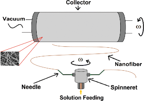
Nanofibers are widely studied materials in filtration (Polat et al. Citation2016), energy (Simon et al. Citation2016), textile (Simsek et al. Citation2016), and biomedical and automotive applications (Hassiba et al. Citation2016). Those are produced via electrospinning, electroblowing, solution blowing, template synthesis, phase separation, self-assembly and fibrillated island-in-the-sea methods (Stojanovska et al. Citation2016; Weng et al. Citation2015). Electrospinning is the most commonly used technique to produce ultrafine nanofibers (Krifa and Yuan Citation2015). Despite its simplicity for lab scale production, electrospinning method has known disadvantages such as high voltage necessity (>10 kV) and low production rate, which limits its usage for industrial applications. Moreover, nanofiber production is very much dependent on material properties such as viscosity, surface tension, conductivity and dielectric constant (Sebe et al. Citation2013). Centrifugal spinning (C-spin) is one of the latest technology, which overcomes the limitations of the electrospinning (Loordhuswamy et al. Citation2014). In the C-spin method, the polymer solution is fed into a rotating chamber (spinneret), consisting of orifices (Mary et al. Citation2013). The centrifugal force generated due to spinneret rotation, pushes the polymer solution towards the inner surfaces of the chamber. When the centrifugal forces overcome the surface tension and viscous forces, the polymer jet exits from the orifices. The polymer jet elongates and the solution evaporates until reaching to the collector, where the nanofibrous web is obtained (Weitz et al. Citation2008).
An important operational parameter of the C-spinning is the rotational speed which was investigated by T. O'Haire et al. This study indicated that the diameter of PP/CNT nanofibers were reduced with the increase of spinneret rotational speed (O'Haire et al. Citation2013). Average nanofiber diameter decreased from 706 nm to 649 nm, when rotational speed was increased from 13000 rpm to 16000 rpm. Other important factors that impact nanofiber morphology are concentration of the polymer solution, the nozzle diameter, and the distance from nozzle to the collector. In a recent study, Lu et al. studied effects nozzle diameter and nozzle-collector distance on the morphology of C-spun polyacrylonitrile (PAN) nanofibers. Effect of nozzle-collector distance on the average fiber diameter was investigated by adjusting the nozzle-collector distance. The average fiber diameters were calculated to be 665, 658, and 647 nm, for the nozzle-collector distances of 10, 20 and 30 cm respectively. It was determined that nozzle-collector distance did not change fiber diameter significantly(Lu et al. Citation2013). However, polymer jet needs a minimum critical nozzle-collector distance to allow the fiber solidification. When the distance is too short, polymer jets could not complete solidification. However, after exceeding the critical distance, fibers cannot get thinner significantly. Similarly, Zander et al. (Citation2015) and Li et al. (Citation2012) also showed that there is not the statistically significant effect of the needle-collector distance on fiber diameter in their studies.
In a study with polyethylene oxide (PEO) nanofibers, it was found that that fiber diameter reduction is proportional to the spinneret orifice and jet diameter (Padron et al. Citation2013). Moreover, it is known that polymer viscosity is directly correlated with its concentration. Badrossamay et al. determined that the diameter of PLA nanofibers increases while polymer concentration increases (Badrossamay et al. Citation2010). While rotational speed was fixed at a constant value, at lower concentrations (4 wt%) they could not produce nanofibers. At higher concentrations (4 wt% < c < 10 wt%), solution viscosity stabilized the jet, resulting in fiber formation. At higher values of the optimal concentration (>10 wt%), solution viscosity limits fiber attenuation resulting in denser microfiber production together with nanofibers.
Average fiber diameter, its distribution and solidity are the main factors on the filtration performance of nanofibrous mats. It can be said that the filtration efficiency improves when the fiber diameter was smaller (Yoon et al. Citation2008; Hung and Leung Citation2011; Ma et al. Citation2011a,Citationb; Barhate and Ramakrishna Citation2007). Liu et al. (Citation2015) found higher performance when the PA66 fiber diameter was below 200 nm. In addition to that, a significant relation was found between the quality factor and the fiber diameter. Mei et al. found that the quality factor decreased (from 0.0375 Pa−1 to 0.0236 Pa−1) when the average fiber diameter increased (from 358 to 1290 nm) for their samples which have similar basis weights (Mei et al. Citation2013). In this research, thermoplastic polyurethane (TPU) nanofibers were produced for air filtration applications. The three dominant parameters (nozzle orifice diameter, rotational speed, polymer concentration) of the centrifugal spinning process were optimized to get thinner fibers. Design of experiment was formed according to Taguchi method and optimum conditions were obtained. The effects of each parameter on the fiber diameter were discussed. Air filtration efficiency tests were done on nanofibrous webs which were produced under optimum conditions.
2. Experimental
2.1. Materials
Polyester based thermoplastic urethane C95 (Mw = 107.010 g/mol) was purchased from BASF Corporation, Germany. TPU was dissolved in the N, N-dimethylformamide (DMF 98%) and heated at 90°C for six hours. Ethyl acetate (13% concentration) was added to this solution and stirred at 50°C for 4 h. The final polymer concentrations were set to 10, 15, and 20 wt%. The nanofibers were collected over a 40 g/m2 spunbond nonwoven polypropylene substrate with an average fiber diameter of 14 ± 2.1 µm.
2.2. Nanofiber production
Nanocentrino L1.0™ (Areka Group LLC.) was used to produce nanofibrous webs. A schematic of the system is given in . The system consists of a spinneret, orifices, and needles. The needles mount onto the orifices. A high-speed motor drives the spinneret. A rotating collector operated via a scalable vacuum pump collects fibers uniformly on its surface. The droplet formation is minimized due to the location of the collector on top of the spinneret.
Three most important factors associated with fiber formation are selected as design factors (Hammami, Krifa, and Harzallah Citation2014). An orthogonal design with three levels was constructed using Taguchi method, which is shown in . The system was operated for different timings to obtain similar basis weights of nanofiber coating around 2.0 ± 0.1 gm−2.
Table 1. Design of experiment.
2.3. Fiber morphology
The morphology of the centrifugally spun nanofibers was examined using a Zeiss EVO MA10 scanning electron microscope (SEM) at 10.00 kV, with magnifications ranging from 1.00 to 10.00 KX. We have taken 100 measurements from the 9 sample images. We have calculated the mean, standard deviations, and distributions from this data. A series of statistical operations were performed as well using the Minitab 18 Software. To determine the optimum parameter levels, the signal to noise (S/N) ratios were calculated based on each level of the parameter. Finally, the analysis of variance (ANOVA) was conducted to determine the effects of parameters and their significance.
2.4. Air filtration performance
Certitest® Automated Air Filter Tester Model 8127 & 8130 was used to measure filtration efficiency. Filtration properties of nanofibrous webs were evaluated with Emery 3004 aerosols in 0.3 µm range at a face velocity of 5.3 cm s−1. Aerosols were generated by using a collision type atomizer and then evaporated through a membrane dryer. Emery 3004 aerosol were fed through a filter with 100 cm2 of effective area and its upstream and downstream concentration levels were measured by using two light-scattering laser photometers simultaneously. The particle penetration value is determined by the ratio of these two levels. Moreover, the pressure drop and the flow rate were measured by using electronic pressure transducers. The quality factor values were calculated using these parameters.
3. Results and discussion
3.1. Fiber morphology
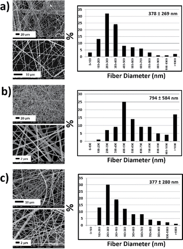
The average fiber diameters and relevant SEM images are shown in through . From the figures, it can be observed that the lowest average fiber diameter was observed in the 8th sample. Although the droplets were eliminated mostly, they were observed locally. Moreover, the beaded structures were at negligible levels. The effect of concentration on the fiber attenuation was clearly seen through all images. Independent from other process factors, larger nozzle diameter led to thicker fibers in all trials. Not only fiber diameter, but also the fiber diameter distribution increased dramatically with the polymer concentration. As a mixture of fine and thicker nanofibers, the samples were fluffier for 20% TPU samples. On the other side, the lowest defect density was also obtained at high concentration. The samples produced at 20% TPU concentrations exhibited the lowest density of defects such as beads and droplets. As it can be seen, samples produced from 10% TPU concentrations had more beads. It is possible to obtain submicron fibers (over 1 µm fiber diameter) in all concentrations, but at high concentrations the density of thicker fibers increases abruptly. Around 15% of the fibers in samples 3 and 5 were submicron fibers, both of which are produced at 20% TPU solution. This is one of the reasons behind the observed large deviation.
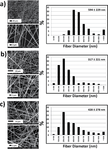
Figure 2. SEM images and diameter distribution of the samples produced with 16G needles. (a) sample 1 (4000 rpm and 10 wt%), (b) sample 2 (8000 rpm and 15 wt%), and (c) sample 3 (12,000 rpm and 20 wt%).
The SEM images of the first three samples with 16G orifice diameter are given in . It can be observed that the ratio of fibers which have submicron diameters was decreased with the increasing concentration and rotational speed. The average fiber diameter was the largest for the sample 3, though the rotation speed was 12,000 rpm and the needle diameter was the lowest. Most probably, the increasing polymer solution feed rate at high rotational speeds led to larger initial jet diameters, which resulted with larger nanofibers. The larger nanofibers might have been produced according to the amount of solution inside rotor reservoir. Though we fixed the solution feed rate via a syringe pump, large solution amount might reach to nozzles at a moment and the centrifugal forces will eject the solution instantly.
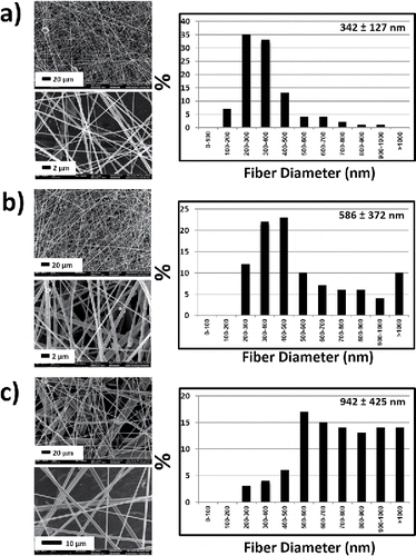
In , the SEM images from 4th to 6th experiments (same orifice diameter, 18G) are shown. When the results of these three experiments evaluated, it was also observed that the diameters increase with high rotational speed and concentration. The effect of polymer solution concentration on the average fiber diameter is clear compared to other parameters.
Figure 3. SEM images and diameter distribution of the samples produced with 18G needles. (a) sample 4 (4000 rpm and 15 wt%), (b) sample 5 (8000 rpm and 20 wt%), and (c) sample 6 (12,000 rpm and 10 wt%).
The SEM images of the last three experimental samples (produced with 22G needles) were shown in . Among all 9 samples, the lowest diameter was observed from sample 8. There were less fibers having a diameter over 1 µm for samples spun from 10% TPU concentration, while there are such microfibers on other samples.
3.2. Optimum conditions
The Taguchi method is an efficient technique to determine the optimum design of experiments. It adopts a signal to noise ratio (S/N) to identify the optimum parameter levels. There are three main approaches for S/N ratios defined by different formulas. These are the “smaller-is-better” approach, the “larger-is-better” approach, and the “nominal-is-best” approach depending on the aim. In order to minimize the fiber diameters, the “lower- is-better” approach is used. The S/N ratio is calculated using EquationEquation (1)[1] (Lin and Chou Citation2010):
[1]
where Yi is the value of average fiber diameters of the ith experiment and n is the number of experiments. The S/N ratios of parameters for each level were shown in . “Level 1” corresponds to the S/N ratios of the first level of each design factors, while “Level 2” and “Level 3” also correspond to the 2nd and 3rd levels, respectively. In addition, “Delta” equals to the difference between the maximum and minimum S / N ratios in the same design factor.
Table 2. S/N ratios of design factors: smaller is better.
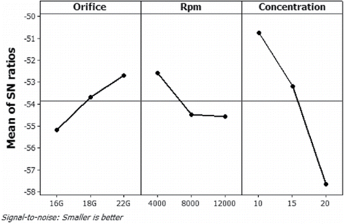
The purpose is the maximization of S/N ratio in order to the determination of optimum levels of parameters. As the signal is increased, the variance is decreased. The corresponding S/N ratios of design factors and S/N ratio graphs were shown in and respectively, according to the average fiber diameters given in .
Figure 5. Average fiber diameters corresponding to the experiments. The boundaries in box plot represent the upper (75th %) and lower (25th %) quartiles. The line represents the median and the plus sign also represents the mean value of fiber diameters.
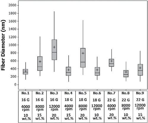
The levels, where S/N ratios are at maximum, give the optimum conditions. From , the O3R1C1 (22G needle as an orifice, 4000 rpm, and 10 wt% concentration of polymer solution) was suggested as optimum conditions. These conditions also assert the best condition for lower fiber diameter among all possible conditions (27 experiments). In , the ranks were ordered by descending delta values for all the factors. The factors which have higher rank and higher delta values are more effective on the fiber diameters. This situation can be explained by analysis of variance in a more detailed way.
Table 3. Analysis of variance for means.
3.3. Analysis of variance (ANOVA)
After analyzing the design of the experiment, the analysis of variance (ANOVA) is required for identification of the significance of determined factors and their interactions. In this study, we have used ANOVA analysis of the average fiber diameter values to determine the effects of various parameters and their significance. This will help us to determine the optimum nanofiber production process parameters. Results from this analysis are indicated in .
It was found that the concentration of polymer solution has a dominant effect on fiber diameter due to the highest percentage contribution (77.52%) according to results of ANOVA as shown in . Moreover, the ANOVA was resulted in about 0.34% of error because of interactions between parameters. It can be seen that this optimization study is not much affected by interactions of parameters. On the other hand, these results are in accordance with the studies of Krifa et al. and Hammami et al. They studied on the beads number on fibers and fiber diameters with ANOVA which showed the concentration as a highly significant effect (Hammami et al Citation2014; Krifa et al. Citation2015).
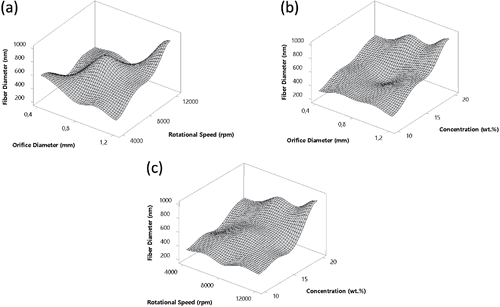
The effects of parameters on the average fiber diameters were given in . The figures show 3D surface plots of optimized parameter values of fiber diameters. The data indicate that the effect of concentration has a dominant impact on fiber diameter. The effect of orifice diameter and rotational speed on fiber diameter is not clearly evident from . On the contrary, the effect of concentration and rotational speed was clearly observed fiber diameter ( and ).
Figure 7. Effect of different C-spin parameters on the average fiber diameters. (a) Orifice diameter and rotational speed, (b) orifice diameter and solution concentration, and (c) rotational speed and solution concentration. The 3rd process parameters which do not appear in graphs have also an effect on diameters.
3.4. Confirmation test
After the analysis of variance, one more experiment under the optimum conditions will be essential to control the consistency. However, average fiber diameter for the optimum conditions can be estimated before performing the confirmation experiment. The optimum conditions are already selected as O3, R1, and C1. Thus, the predicted average fiber diameter under this condition has been computed as (Chaulia and Das Citation2008; Singh and Kumar Citation2004; Harris Citation1989):[2]
where is the overall average fiber diameter corresponding to .
,
and
are the average values of the fiber diameter with parameters at the optimum condition levels and μ is the estimated average fiber diameter for the optimum condition. According to this equation, the average diameter of the optimum condition has been predicted to be 172.4 nm.
Figure 8. SEM images and fiber diameter distributions of the optimum condition (22G, 4000 rpm, 10 wt%), respectively.
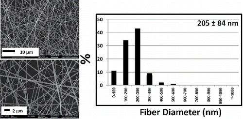
Figure 9. Average fiber diameters corresponding to all the 9 experiments, sample 8, and the experiment at the optimum condition, respectively. The boundaries in box plot represent the upper (75th%) and lower (25th%) quartiles. The line and plus sign represents median and represent the mean value of fiber diameters, respectively.
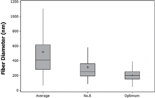
In order to confirm the predicted results, an experiment was implemented using the optimum levels which are the 22G gauge of the needle as an orifice, the 4000 rpm as a rotational speed of spinneret, and the 10 wt% concentration of polymer solution. The average fiber diameter at the optimum conditions was 205±84 nm as shown in and . Compared to experiment 8the result showed a 35% reduction in fiber diameter. Moreover, the optimized value was 61% lower than the average fiber diameters of all 9 experiments with a lower standard deviation.
3.5. Air filtration performance
The produced nanofibrous substrates with different fiber diameters were tested as single, double and triple layers. Sample 3 (16G, 12,000 rpm, 15 wt%), sample 8 (22G, 8000 rpm, 10 wt%) and optimized samples were analyzed. In addition to these, the uncoated polypropylene (PP) spunbond nonwoven was also tested as a reference media.
The penetration values (P) was determined by the ratio of downstream and upstream particle concentrations (P = Cdown/Cup) (Chang et al. Citation2015). The resistance values corresponding to the penetration percentages of samples were plotted on semilog graphs () where linear regression lines were also drawn.
Figure 10. Percentage of penetration versus resistance curves of fibrous samples challenged with 0.3 µm Emery 3004 particles.
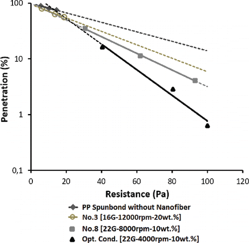
The filter efficiencies were calculated using the equation η = 1-P (Chang et al. Citation2015) The reference spunbond media exhibited minor efficiency (around 20%) at an expense of 15 Pa pressure drop. However, the performance of the fabrics increased significantly after nanofibrous coating. The efficiency of the optimized sample was found to be highest at a significantly low pressure drop. Nanofibrous webs having an average diameter of 942 nm and 317 nm exhibited capture efficiency of 45.4% and 95.9%, respectively, while optimized sample with a diameter of 205 nm exhibited 99.4%. The linear regression curves for penetration vs. resistance clearly show that as the fiber diameter decreased, the filtration efficiency increased significantly.
In addition, the quality factor values were determined, which is related to the capture efficiency of aerosol particles by the air resistance across the filter media (Kilic et al. Citation2015). It was also calculated as QF = –lnP/Δp. where P is the penetration and Δp is the pressure drop across the media. The results were shown in . From the plot, it can be observed that with a reduction in fiber diameter, the quality factor values increased. The optimized sample exhibited the highest quality factor, which is due to low penetration ratio at an expense of lower air resistance. The smaller fiber diameter allowed the slip flow regime through the filter media, which is confirmed by dimensionless Knudsen number. The Knudsen number (Kn) can be defined as the ratio of the mean free path length to the fiber diameter (EquationEquation (3)[3] and describe flow type through porous media (Balgis et al. Citation2015; Bao et al. Citation2016):
[3]
Figure 11. Quality factor values of different triple layer samples challenged with Emery 3004 aerosols. The Knudsen number for PP spunbond without NF is 0.007, while No 3 is 0.140, No 8 is 0.416, and Opt. Cond. is 0.644.
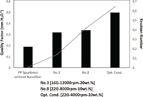
where λ is a mean free path length of carrier gas (λ = 0.065 µm for air at standard conditions) and df is the fiber diameter. Slip flow occurs when Kn is greater than 0.1. The results indicate that the nanofiber layers experience a slip flow effect () which is most probably the reason behind the high quality factors.
4. Conclusion
This research aimed to investigate the optimum conditions to produce C-spun TPU nanofibers. 9 samples were produced based on an L9 orthogonal array and the optimum process parameter levels were found by Taguchi method. TPU solutions with three different concentrations were processed at three different rotational speeds using orifices with three different diameters. The minimum average fiber diameter (205 ± 84 nm) at the optimum conditions was observed at the 22G orifice, 4000 rpm, and 10 wt% concentration of polymer solution. Moreover, the ANOVA was performed to find the effects of process parameters on fiber diameter. The results were statistically significant. The effect of concentration of polymer solution was found to contribute approximately 77.5% on the fiber diameter variation.
The filtration performances of the nanofibrous substrate composed of various fiber diameters (including the optimized condition) were analyzed. The maximum filtration efficiency, Knudsen number, and quality factor values with the minimum penetration were observed for the optimized sample. The filtration performance was dominated by the average fiber diameter. It was also observed that the filtration efficiency of the optimized sample approximates to E12 level efficiency at an expense of 98 Pa pressure drop. This indicates that centrifugal spinning with higher fiber production efficiency is a viable route to produce high performance air filters. In addition, reduction of fiber diameters using novel polymer solutions and original rotor designs might open new possibilities in nanofibrous media and air filtration studies.
Acknowledgments
The authors gratefully acknowledge AREKA LLC. for the lab scale centrifugal spinning system.
Additional information
Funding
References
- Badrossamay, M. R., McIlwee, H. A., Goss, J. A., and Parker, K. K. (2010). Nanofiber Assembly by Rotary Jet-Spinning. Nano Lett., 10(6):2257–2261. doi:10.1021/nl101355x.
- Balgis, R., Kartikowati, C. W., Ogi, T., Gradon, L., Bao, L., Seki, K., and Okuyama, K. (2015). Synthesis and Evaluation of Straight and Bead-Free Nanofibers for Improved Aerosol Filtration. Chem. Eng. Sci., 137:947–954. doi:10.1016/j.ces.2015.07.038.
- Bao, L., Seki, K., Niinuma, H., Otani, Y., Balgis, R., Ogi, T., Gradon, L., and Okuyama, K. (2016). Verification of Slip Flow in Nanofiber Filter Media through Pressure Drop Measurement at Low-Pressure Conditions. Sep. Purif. Technol., 159:100–107. doi:10.1016/j.seppur.2015.12.045.
- Barhate, R. S., and Ramakrishna, S. (2007). Nanofibrous Filtering Media: Filtration Problems and Solutions from Tiny Materials. J. Membr. Sci., 296(1):1–8. doi:10.1016/j.memsci.2007.03.038.
- Chang, D.-Q., Chen, S.-C., Fox, A. R., Viner, A. S., and Pui, D. Y. H. (2015). Penetration of Sub-50 Nm Nanoparticles Through Electret HVAC Filters Used in Residence. Aerosol Sci. Technol., 49(10):966–976. doi:10.1080/02786826.2015.1086723.
- Chaulia, P. K., and Das, R. (2008). Process Parameter Optimization for Fly Ash Brick by Taguchi Method. Mater. Res., 11(2):159–164. doi:10.1590/S1516-14392008000200008.
- Hammami, M. A., Krifa, M., and Harzallah, O. (2014). Centrifugal Force Spinning of PA6 Nanofibers – Processability and Morphology of Solution-Spun Fibers. J. Text. Inst., 105(6):637–64. doi:10.1080/00405000.2013.842680.
- Harris, L. N. (1989). Taguchi Techniques for Quality Engineering, Philip J. Ross, Mcgraw-Hill Book Company, 1988. Qual. Reliability Eng. Int., 5(3):249–249. doi:10.1002/qre.4680050312.
- Hassiba, A. J., El Zowalaty, M. E., Nasrallah, G. K., Webster, T. J., Luyt, A. S., Abdullah, A. M., and Elzatahry, A. A. (2016). Review of Recent Research on Biomedical Applications of Electrospun Polymer Nanofibers for Improved Wound Healing. Nanomedicine, no. 0. doi:10.2217/nnm.15.211.
- Hung, C.-H., and Leung, W. W.-F. (2011). Filtration of Nano-Aerosol Using Nanofiber Filter under Low Peclet Number and Transitional Flow Regime. Sep. Purif. Technol., 79(1):34–42. doi:10.1016/j.seppur.2011.03.008.
- Kilic, A., Shim, E., and Pourdeyhimi, B. (2015). Electrostatic Capture Efficiency Enhancement of Polypropylene Electret Filters with Barium Titanate. Aerosol Sci. Technol., 49(8):666–673. doi:10.1080/02786826.2015.1061649.
- Krifa, M., Hammami, M. A., and Wu, H. (2015). Occurrence and Morphology of Bead-on-String Structures in Centrifugal Forcespun PA6 Fibers. J. Text. Inst., 106(3):284–294. doi:10.1080/00405000.2014.917812.
- Krifa, M., and Yuan, W. (2015). Morphology and Pore Size Distribution of Electrospun and Centrifugal Forcespun Nylon 6 Nanofiber Membranes. Text. Res. J., 0040517515609258.
- Li, X., Liu, H., Wang, J., and Li, C. (2012). Preparation and Characterization of Poly(ϵ-Caprolactone) Nonwoven Mats via Melt Electrospinning. Polymer, 53(1):248–253. doi:10.1016/j.polymer.2011.11.008.:10.1016/j.polymer.2011.11.008.
- Lin, H.-L., and Chou, C.-P. (2010). Optimization of the GTA Welding Process Using Combination of the Taguchi Method and a Neural-Genetic Approach. Mater. Manuf. Processes, 25(7):631–636. doi:10.1080/10426910903365711.
- Liu, B., Zhang, S., Wang, X., Yu, J., and Ding, B. (2015). Efficient and Reusable Polyamide-56 Nanofiber/Nets Membrane with Bimodal Structures for Air Filtration. J. Colloid Interface Sci., 457:203–211. doi:10.1016/j.jcis.2015.07.019.
- Loordhuswamy, A. M., Krishnaswamy, V. R., Korrapati, P. S., Thinakaran, S., and Rengaswami, G. D. V. (2014). Fabrication of Highly Aligned Fibrous Scaffolds for Tissue Regeneration by Centrifugal Spinning Technology. Mater. Sci. Eng.: C, 42:799–807. doi:10.1016/j.msec.2014.06.011.
- Lu, Y., Li, Y., Zhang, S., Xu, G., Fu, K., Lee, H., and Zhang, X. (2013). Parameter Study and Characterization for Polyacrylonitrile Nanofibers Fabricated via Centrifugal Spinning Process. Eur. Polym. J., 49(12):3834–3845. doi:10.1016/j.eurpolymj.2013.09.017.
- Ma, H., Burger, C., Hsiao, B. S., and Chu, B. (2011a). Ultra-Fine Cellulose Nanofibers: New Nano-Scale Materials for Water Purification. J. Mater. Chem., 21(21):7507–7510. doi:10.1039/c0jm04308g.
- Ma, H., Hsiao, B. S., and Chu, B. (2011b). Thin-Film Nanofibrous Composite Membranes Containing Cellulose or Chitin Barrier Layers Fabricated by Ionic Liquids. Polymer, 52(12):2594–2599. doi:10.1016/j.polymer.2011.03.051.
- Mary, L. A., Senthilram, T., Suganya, S., Nagarajan, L., Venugopal, J., Ramakrishna, S., and Giri Dev, V. R. (2013). Centrifugal Spun Ultrafine Fibrous Web as a Potential Drug Delivery Vehicle. Exp. Polym. Lett., 7(3):238–248. doi:10.3144/expresspolymlett.2013.22.
- Mei, Y., Wang, Z., and Li, X. (2013). Improving Filtration Performance of Electrospun Nanofiber Mats by a Bimodal Method. J. Appl. Polym. Sci., 128(2):1089–1094. doi:10.1002/app.38296.
- O'Haire, T., Rigout, M., Russell, S., and Carr, C. (2013). Influence of Nanotube Dispersion and Spinning Conditions on Nanofibre Nanocomposites of Polypropylene and Multi-Walled Carbon Nanotubes Produced through ForcespinningTM. J. Thermoplast. Compos. Mater., 0892705713495222.
- Padron, S., Fuentes, A., Caruntu, D., and Lozano, K. (2013). Experimental Study of Nanofiber Production through Forcespinning. J. Appl. Phys., 113(2):024318. doi:10.1063/1.4769886.
- Polat, Y., Pampal, E. S., Stojanovska, E., Simsek, R., Hassanin, A., Kilic, A., Demir, A., and Yilmaz, S. (2016). Solution Blowing of Thermoplastic Polyurethane Nanofibers: A Facile Method to Produce Flexible Porous Materials. J. Appl. Polym. Sci., 133(9). http://onlinelibrary.wiley.com/doi/10.1002/app.43025/full. doi:10.1002/app.43025.
- Sebe, I., Szabó, B., Nagy, Z. K., Szabó, D., Zsidai, L., Kocsis, B., and Zelkó, R. (2013). Polymer Structure and Antimicrobial Activity of Polyvinylpyrrolidone-Based Iodine Nanofibers Prepared with High-Speed Rotary Spinning Technique. Int. J. Pharm., 458(1):99–103. doi:10.1016/j.ijpharm.2013.10.011.
- Simon, B., Bachtin, K., Kiliç, A., Amor, B., and Weil, M. (2016). Proposal of a Framework for Scale-up Life Cycle Inventory: A Case of Nanofibers for Lithium Iron Phosphate Cathode Applications. Integr. Environ. Assess. Manage. http://onlinelibrary.wiley.com/doi/10.1002/ieam.1788/abstract. doi:10.1002/ieam.1788.
- Simsek, R., Polat, Y., Pampal, E. S., Agma, O., and Kilic, A. (2016). Ultrasonic Coating of Nanofibrous Webs: A Feasible Approach to Photocatalytic Water Filters. J. Coat. Technol. Res., 13(1):89–95. doi:10.1007/s11998-015-9718-8.
- Singh, H., and Kumar, P. (2004). Tool Wear Optimization in Turning Operation by Taguchi Method. Indian J. Eng.Mater. Sci., 11(1):19–24.
- Stojanovska, E., Canbay, E., Pampal, E. S., Calisir, M. D., Agma, O., Polat, Y., Simsek, R., Gundogdu, N. A. S., Akgul, Y., and Kilic, A. (2016). A Review on Non-Electro Nanofibre Spinning Techniques. RSC Advances, 6(87):83783–83801. doi:10.1039/C6RA16986D.
- Weitz, R. T., Harnau, L., Rauschenbach, S., Burghard, M., and Kern, K. (2008). Polymer Nanofibers via Nozzle-Free Centrifugal Spinning. Nano Lett., 8(4):1187–1191. doi:10.1021/nl080124q.
- Weng, B., Xu, F., Garza, G., Alcoutlabi, M., Salinas, A., and Lozano, K. (2015). The Production of Carbon Nanotube Reinforced Poly (Vinyl) Butyral Nanofibers by the Forcespinning® Method. Polym. Eng. Sci., 55(1):81–87. doi:10.1002/pen.23872.
- Yoon, K., Hsiao, B. S., and Chu, B. (2008). Functional Nanofibers for Environmental Applications. J. Mater. Chem., 18(44):5326–5334. doi:10.1039/b804128h.
- Zander, N. E. (2015). Formation of Melt and Solution Spun Polycaprolactone Fibers by Centrifugal Spinning. J. Appl. Polym. Sci., 132(2):n/a–n/a. doi:10.1002/app.41269.

