
Abstract
Previous numerical studies that have used computational fluid dynamics (CFD) and experimental software to address the effects of the geometric parameters of pleats on the pressure drop and air flow rate through a fibrous filter are analyzed. The analysis establishes that using a test dust with gradually smaller particle sizes (10, 5, and 1 μm) results in a more intense increase in the filter pressure drop, thus decreasing the service life of the filter. The benefits of using a multicyclone as the first stage of air filtration are discussed. Selecting the air filter by determining the active surface of the filter medium Ac based on the allowable filtration rate is not sufficient; to select the filter medium of a motor vehicle air filter, the dust mass retained per unit of filtration area (mass loading of dust km) must be known for a specific allowable pressure drop Δpfdop. New methods and conditions for determining the mass loading of dust km for filter paper and non-woven fabric in single-stage and two-stage filtration systems are presented. The characteristics of the separation efficiency and filtration performance as well as the pressure drop of a filter set comprising a single cyclone and a filter element with a specific filter medium surface are determined. The effects of the particle size distribution of the dust in the air downstream of the cyclone on the mass loading of dust km of the filter paper and non-woven fabric in a two-stage filtration system are presented. The mileage of a truck fitted with a single-stage or two-stage filtration system in a “multicyclone–panel filter” configuration is estimated based on the calculated mass loading of dust km of the filter paper and non-woven fabric.
© 2018 American Association for Aerosol Research
EDITOR:
1. Introduction
The inlet air filtration systems in the engines of modern passenger cars use single-stage filters with panel filters constructed from pleated filter paper or, less often, non-woven fabric. Trucks, heavy vehicles, military vehicles (mostly tanks, infantry combat vehicles, and armored personnel carriers) subjected to high dust concentration conditions are usually fitted with two-stage filtration systems. The first stage is an inertial filter featuring a multicyclone or a mono-cyclone with vortex-inducing guide vanes, and the second filtration stage is a cylindrical porous panel filter consisting of pleated filter paper. A multicyclone is a set of several cyclones arranged side by side with an internal diameter not exceeding D = 40 mm.
Filter paper is the filter medium predominantly used in the inlet air filtration systems of modern motor vehicles. The filter paper is arranged in the filter element as a pleated band; V-shaped pleats are the most commonly used. The filter element shape should feature a maximum surface area at a minimum volume while maintaining a maximum air flow rate—filtration rate υFmax, which should not exceed 0.07–0.12 m/s for passenger car filters and 0.03–0.06 m/s for truck filters (Erdmannsdörfer Citation1971; Taufkirch and Mayr Citation1984; Bugli Citation2001; Durst et al. Citation2005). In passenger cars, the air filter is attached to the car body in the engine compartment, and the design of the filter thus corresponds to the limited space available in the engine compartment.
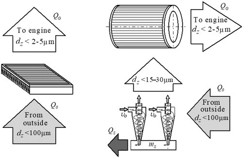
Filter elements made of pleated paper shaped as cuboidal panels are widely used in many modern passenger cars and trucks. Depending on the operating conditions of the vehicle, the intake air contains dust particles with a diameter dz of 50–100 µm. Silicone oxide (SiO2), which has a Mohs hardness of 7, is the main component of mineral dust, and its content in the total dust mass may be as high as 95%. In a two-stage filter, large dust particles are first retained in the inertial filter, while small dust particles (dz < 15–30 µm) are retained at a pleated filter paper with performance above dz = 2–5 µm ().
Figure 1. Air filtration process: (a) single-stage filter (porous panel filter); (b) two-stage filter (multicyclone–porous panel filter) of a truck.
The time required by the air filtration system in the motor to reach the allowable pressure drop Δpfdop is extended (Taufkirch and Mayr Citation1984; Bugli Citation2001; Durst et al. Citation2005).
This extends (over 200%) the time of using air engine filtration system (vehicle mileage Sp), until permissible value of pressure drop Δpfdop (Bugli Citation2001; Durst et al. Citation2005; Taufkirch and Mayr Citation1984) is reached, which is a signal to replace filter cartridge with a new one. Filter cartridges from pleated paper can be regenerated with a pulsed-jet air. Experimental studies in this area have been presented (Lo, Chen, and Pui Citation2010; Yan, Liu, and Chen Citation2013; Li, Li, and Zhou Citation2015).
In practice, the filter paper is selected by determining its surface area based on the allowable filtration rate υFdop and the air demand Qs of the engine. The study shows that this is not sufficient to ensure a required air filter service life, which is limited by an allowable pressure drop Δpfdop, used as a criterion of the end of its service life. The service life of the filter until the allowable pressure drop Δpfdop is reached depends not only on the air filtration parameters of the porous panel filter but also on its absorption capacity, which is related to its structure and the size of the retained dust particles.
A single-stage filter, usually with a pleated filter paper as its filter element, sucks dust particles up to dz = 100 μm directly from the surrounding air. According to Jaroszczyk and Ptak (Citation1985), Yang, Sun, and Gao (Citation2013), Haig et al. (Citation2014), Baltrėnas and Chlebnikovas (Citation2015) and studies of a single cyclone system by Dziubak and Szwedkowicz (Citation2013a), Dziubak (Citation2006, Citation2017), in the two-stage intake air filtration systems (multicyclone–filter paper) used in trucks and special-purpose vehicles, the dust downstream of the cyclones has a disparate particle size distribution, and thus the second stage of filtration (filter paper) is only reached by small dust particles up to dz = 15–35 μm.
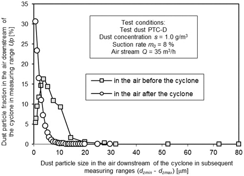
shows the granulometric composition of the PTC-D test dust (Arizona test dust) in the air before, and after the cyclone. The air in front of the cyclone contains particles with a maximum size of 80 μm. In the cyclone, particles of the largest size and mass are released from the air, which results in remaining particles below about dzmax = 30 µm. The numerical fraction of the particles with the maximum size of dzmax = 0.7 µm in the air, before the cyclone has the value Up1 = 5.4%, and after the cyclone Up2 = 30.6%. The particle size is moved toward a smaller size.
Figure 2. Granulometric dust composition in the air, before and after cyclone for air stream QG =35 m3/h.
Thus, the filtration process may differ for filter paper used as the second filtration stage (downstream of the multicyclone) compared to a single-stage filtration system. If a porous panel filter (filter paper or non-woven fabric) is subjected to small dust particles, the dust particles will form a more compact and less permeable structure, resulting in increased pressure drop due to the lower air permeability of the dust layer. The filter therefore reaches the allowable pressure drop Δpfdop much earlier and at a lower mass of retained dust. The dust mass retained per unit of filtration area will be lower due to the significantly lower capacity of the filter panel to retain small dust particles. This effect has been observed during numerical tests of fibrous materials (Saleh and Tafreshi Citation2014; Saleh et al. Citation2013, Citation2014, Citation2015) and experimental tests of a “cyclone–pleated filter paper” filtration system (Dziubak and Szwedkowicz Citation2013b, Citation2015). Under actual operating conditions, the service life of the filter is reduced because the filter reaches the allowable pressure drop Δpfdop. Knowledge of the mass loading of dust km of the filter medium used as the second filtration stage (downstream of the multicyclone) is important when designing an air filter to determine the vehicle mileage at which the allowable pressure drop Δpfdop will be reached.
To design a two-stage air filter, the mass loading of dust km must be determined for actual operating conditions. The filtration process of small dust particles at the pleated filter paper (non-woven filter) has not been thoroughly studied and described in the literature.
This study analyses test results available in the literature based on computational fluid dynamics (CFD) software. The included studies examined the effects of the geometry of the filter medium pleats, aerosol properties, and mass of retained dust on the pressure drop and separation efficiency both inside and on the surface of fibrous panel filters. The aim of this analysis was to use the results in the design of paper panel filters for use in trucks. To select a suitable air filter for a truck, an innovative method was used to determine the mass loading of dust km of the filter medium used as the second filtration stage (filter paper or non-woven fabric) directly downstream of the inertial filter.
2. Modeling filtration in fibrous panel filters
The aerosol filtration process in a porous panel filter is a very complex process variable in time that depends on many factors and is characterized by the interactions of particles in the dispersed phase (dust) and the dispersion phase (air) with the filter elements of the porous panel filter. Dust particles are retained inside the filter and on its surface via various filtration mechanisms. At the initial stage, the particles settle on the fibers, form branched dendritic structures, couple with each other, and fill the voids between the fibers. The structure and porosity of the filter bed change as a result of the filtration process and settling of dust particles on the filter elements of the porous panel filter.
The basic parameters used to determine air filter quality are separation efficiency (φ) and pressure drop (Δp). Air filters with pleated paper elements are capable of reaching a separation efficiency of 99.9%, filtration performance >2–5 µm, and an allowable pressure drop Δpfdop of 4–7 kPa. Similar Δpfdop values cannot be reached by inertial filters and electrostatic precipitators (Kim et al. Citation2013; Feng, Long, and Chen Citation2014).
The separation efficiency of motor vehicle air filters using a pleated filter paper element depends on many parameters, including the dust, filter bed, air, and operating conditions. The separation efficiency of an inertial air filter (multicyclone) is a function of the following parameters: the dust, cyclone geometry (inlet port, vanes, cyclone body, outlet port), cyclone type, gas flow conditions (clean gas flow rate as the average flow rate at the inlet port υ0), and dust extraction rate from the dust collector.
Given the large number of parameters determining the efficiency of a pleated filter paper, the high processing power of modern computers and CFD software can be used to eliminate time-consuming and expensive experimental tests at the design stage. Although experimental tests are the most reliable means of evaluating the efficiency of engine air filters and pollen filters, they are not widely used due to their high complexity and costs.
Numerical tests of fibrous materials, including filter papers, are complicated by their randomly distributed, unordered microstructure, which is difficult to model. Reported numerical simulations usually focus on three categories: uni-directional structures in which the axes of all cylindrical fibers are parallel (Spielman and Goren Citation1968; Jackson and James Citation1986; Chen and Papathanasiou Citation2006) random structures in which the axes of cylindrical fibers are randomly distributed in parallel planes, usually parallel to the flow direction (Koponen et al. Citation1998; Dhaniyala and Liu Citation1999; Wang et al. Citation2007; Zobel et al. Citation2007; Jaganathan et al. Citation2008; Tafreshi et al. Citation2009) and 3D isotropic structures in which the axes are randomly oriented in any direction in a 3D space (Spielman and Goren Citation1968; Jackson and James Citation1986; Higdon and Ford Citation1996).
Flow through a 3D structure of randomly distributed bars in all three dimensions was solved by (Spielman and Gorena Citation1968) using analytical techniques. Jackson and James (Citation1986) proposed a new expression for 3D structures with horizontally arranged fibers or fibers randomly distributed in all directions in a 3D space. Higdon and Ford (Citation1996) calculated the permeability of 3D models of a fibrous structure based on an ordered networks of fibers. Further studies of fibrous 3D structures were presented in Chen, Pui, and Liu (Citation1995), Clague and Phillips (Citation1997), Tung et al. (Citation2006), Tahir and Tafreshi (Citation2009), and Hosseini and Tafreshi (Citation2010a).
The first use of numerical simulation to study the effects of pleat geometry on the operation of fibrous filters was presented in 1995 by Chen et al. (Citation1995), who calculated the pressure drop in the absence of dust particles in a fibrous filter with rectangular pleats. Chen et al. proved there is an optimum number of pleats at which the pressure drop in a clean filter medium has a minimum value. Similar tests were published by Lücke and Fissan (Citation1996). Simulations of airflow in clean filters to optimize the geometry of the filter medium pleats have also been performed for cylindrical filters and panel filters for various applications (Caesar and Schroth Citation2002; Del Fabbro et al. Citation2002; Subrenat, Bellettre and Cloirec Citation2003; Tronville and Sala Citation2003; Wakeman et al. Citation2005; Waghode et al. Citation2007; Lo et al. Citation2010; Rebai et al. Citation2010).
The first numerical simulation of dust-laden filters focused mainly on modeling dust settling on individual fibers. The results of the study were further used to predict the performance of the filter as a whole as a system of many unordered fibers characterized by different aerodynamic and dust loading properties. These pioneering studies, first by (Payatakes and Tien Citation1976) and then by other researchers (Payatakes and Gradoń Citation1980; Kanaoka, Emi, and Myojo Citation1980; Filippova and Hanel Citation1997; Kanaoka, Hiragi, and Tanthapanichakoon Citation2001; Lantermann and Hänel Citation2007; Li and Marshall Citation2007; Hosseini and Tafreshi Citation2012), each contributed to the development of modeling techniques for individual dust-laden fibers.
The simulation results for individual fibers cannot be used to accurately predict the performance of the fibrous filter as a whole. Saleh et al. (Citation2013) and Subrenat, Bellettre, and Cloirec (Citation2003) developed a 3D simulations methods at the micro-scale (corresponding to the fiber diameter) to predict the momentary pressure drop and separation efficiency of fibrous media depending on the dust particle parameters.
Macro-scale calculation methods (CFD) have been used to simulate the accumulation of dust particles and a layer of dust (filter cake) on the surface of a fibrous filter bed and its effects on the efficiency of pleated fibrous materials (Saleh et al. Citation2013, Citation2014, Citation2015; Saleh and Tafreshi Citation2014; Fotovati et al. Citation2011, Citation2012; Tien and Ramarao Citation2013; Théron et al. Citation2017). Data from previous numerical studies of both clean and dust-laden filter papers in a flat configuration (Wang et al. Citation2006; Hosseini and Tafreshi Citation2010b,c; Fotovati et al. Citation2010; Théron et al. Citation2017) were used in calculations.
In another study, Saleh et al. (Citation2015) presented a 2D model to simulate the instantaneous pressure drop and separation efficiency of a circular (ring type) filter made of pleated paper as a function of time, both inside and on the surface of the filter. The filter medium was a filter bed in the form of triangular pleats 25.4 mm high and 0.7 mm thick with a fiber diameter of 15 μm. The panel filter material was shaped to form two and four pleats with a length of one inch at inclination angles γ1 = 7.125° and γ2 = 14.25°. The circular filters included 28 and 32 pleats, resulting in inlet diameters of 64.8 and 56.8 mm, respectively. The efficiency was tested using 1- and 10-μm monodisperse dust. The study showed that the circular filters made of pleated non-woven fabric with a high inlet-to-outlet diameter ratio had higher efficiency than their flat equivalents but a higher pressure drop. This effect was more pronounced at higher inclination angles γ because the dust particles tended to settle deep inside the filter medium due to the high inlet-to-outlet diameter ratio, leaving a thin, relatively more permeable filter cake at the surface of the pleats.
Flow tests were performed for three different geometric configurations of the filter (different pleat heights and widths) at u = 0.8 m/s (Théron et al. Citation2017). The filter medium was a filter bed made of cotton and polyester fibers 2.8 mm thick with a fiber diameter of 13.8 μm and a unit weight of 65 ± 5 g/m2. For a specific pleat height, the pressure drop decreased with increasing pleat width. Within the range of tested widths and heights, the minimum pressure drop was achieved using high-width and low-height pleats. The effects of the geometric properties of the pleats on the pressure drop was more pronounced as the air filtration rate increased.
Saleh and Tafreshi (Citation2014) presented a semi-numerical 2D model simulating the effects of pleat geometry, aerosol properties, and dust loading on the pressure drop and separation efficiency both inside and on the surface of fibrous filters (panel filters with rectangular or triangular pleats). The material was shaped to form two or four rectangular pleats per inch. The filter efficiency was tested as a function of time and the dust mass retained per unit of filtration area using 1-, 5-, and 10-μm monodisperse dust particles with an aerosol mass concentration of 0.252 mg/m3 and filtration rates of 0.1, 0.5, and 1 m/s.
Retention of the dust particles on the fibrous layer resulted in increases in separation efficiency and pressure drop; however, the values of both parameters were lower for the filter with a greater number of pleats and a greater filtration area. As the number of pleats increased, a lower dust mass was retained by each channel formed by two adjacent pleats in a unit of time. As the particle size of the test dust gradually decreased (10, 5, and 1 μm), the increase in pressure drop became greater, and consequently, the allowable pressure drop was reached earlier. Thus, the dust mass retained per unit of filtration area was lower. Regardless of the filtration rate, the filters with rectangular plates exhibited a higher dust absorption capacity per unit of filtration area than the equivalent filters with triangular pleats.
The numerical studies involved simulations of 1-, 5-, and 10-µm monodisperse dust particles and 1–10-µm polydisperse dust particles. Under the actual operating conditions of an internal combustion engine of a motor vehicle used on public roads, the filter sucks from air significantly larger polydisperse dust particles up to 100 µm in diameter (Jaroszczyk Citation1987; Dziubak Citation2000; Mahowald et al. Citation2014; Rivera and Rodriguez Citation2016).
The mass concentration of particles in the air was used in the numerical simulations s = 0.252 mg/m3 (Saleh and Tafreshi Citation2014). The dust concentration in the air surrounding the vehicle when used on hard surfaces was ∼s = 0.1–3 mg/m³, whereas on soft surfaces, at construction sites or quarries, the concentration was >80 mg/m3 (Schulze and Taufkirch Citation1991; Barris Citation1995; Durst et al. Citation2005; Sanders et al. Citation2007). For tracked vehicles used on testing grounds, the dust concentration in the air exceeded s = 1000 mg/m³ by a large margin (Jaroszczyk Citation1987; Schaeffer and Olson Citation1998; Dziubak Citation2000; Grafe et al. Citation2001). However, none of the analyzed numerical models included a model simulating air filtration in a two-stage filter system in series with a “multicyclone–pleated paper” configuration supplied with a stream of air with a high concentration (s = 1000–7000 mg/m3) of polydisperse dust. Such studies would greatly aid the design of a two-stage inlet air filtration system for motor vehicles used under high dust concentration conditions.
Due to the characteristics (separation efficiency and pressure drop) of a complete single stage (with pleated filter paper) and two-stage (multicyclone–pleated paper) air filter, in this study, motor vehicle engines were tested on a test stand as a function of a single selected parameter, e.g., mass of dust retained on the filter element, stream of air flow, and dust particle size, which is both expensive and time-consuming.
3. Method of selecting a filter paper for the air filter
To select an inlet air filter, the active filtration area of the filter medium Ac (most often paper or non-woven fabric) that meets the condition of the allowable air flow rate through the filter bed, i.e., υFdop, at the nominal air demand of the engine must be determined. The active filtration area is calculated using the following formula:
(1)
where QNs—nominal air demand of the engine [m3/h].
This study shows that the active filtration area is not sufficient to ensure the required air filter service life, which is limited by the allowable pressure drop Δpfdop. The allowable pressure drop Δpfdop is used as a criterion for the end of the filter service life. The service life of the filter until Δpfdop is reached depends not only on the air filtration parameters of the porous panel filter but also on its absorption capacity, which is related to the structure of the filter and the size of the retained dust particles.
Whether the surface area Ac selected based on the allowable filtration rate guarantees the required service life τp of the filter (vehicle mileage) against maintenance (replacement of the filter element) at the allowable pressure drop Δpfdop is also important. Service life of the filter can be determined based on the performance tests of a complete air filter directly on the vehicle or in the laboratory conditions. It is much easier to estimate the service life τp of a two-stage air filter from a theoretical formula (Melzer and Brox Citation1984).
(2)
where km—filter paper mass loading of dust [g/m2], kc—coefficient corresponding to the differences in parameters between test dust particles and actual dust particles, s—dust concentration at the filter inlet [g/m3], φm—multicyclone separation efficiency, φp—filter paper separation efficiency.
Using this formula to predict the service life of a filter requires the availability of many experimental data characterizing a specific filter paper. Filter paper manufacturers usually specify the parameters defining the paper structure: thickness, pore size, basis weight, mechanical strength, pressure drop (permeability), and density.
To determine the required vehicle mileage (service life of the filter) under specific operating conditions, the dust absorption capacity of the filter medium, i.e., the dust mass retained per unit of filtration area, must be known. This property is characterized by the mass loading of dust km of the filter medium, which is defined as the ratio of the total dust mass mcw retained by the filter element until reaching the allowable pressure drop Δpfdop to the active filtration area Ac of the paper used as the filter element.
(3)
It was assumed that the retained dust mass is evenly distributed on the filtration surface. From the research presented in Fotovati et al. (Citation2011); Saleh et al. (Citation2013, Citation2014, Citation2015), Saleh and Tafreshi (Citation2014), Théron et al. (Citation2017), the dust layer is unevenly deposited on a pleated filter layer.
For standard cellulose-based filter media and standard dusts with particle sizes <100 μm, km = 240 g/m2 (Bugli Citation2000, Citation2001; Durst et al. Citation2005). Discrepant values of the mass loading of dust have been reported for non-woven fabrics. Dhaniyala and Liu (Citation1999) reported an mass loading of dust km of 54.5–89.3 g/m2 for a non-calendered non-woven fabric with a thickness of 3.2 mm at a pressure drop of 0.3 kPa but 85.5–112.3 g/m2 for an identical calendered fabric. Durst et al. (Citation2005) demonstrated that the mass loading of dust km of non-woven fabric filters with a gradient structure was 900–1100 g/m2. The pressure drop value at which km was determined was not specified. Mass loading of dust km for non-woven filter fabrics exceeding 400–480 g/m2 have also been reported (www.retopfibre.en.alibaba 2017).
The mass loadings of dust km were determined for the materials used in a single-stage filtration system of a passenger car. Calculating the service life τp of a two-stage air filter based on the mass loading of dust km of a filter medium determined for a single-stage filter can be misleading. Thus, the mass loading of dust km must be determined for the filter medium for operation in a two-stage “multicyclone–panel filter” configuration.
This study presents a less expensive and less complex method to determine the mass loading of dust of paper and non-woven fabric filters. This method consists of testing a section of the actual two-stage filtration system. The two-part section of the filter, referred to as the “filter set,” includes the cyclone and tested filter element installed in series and represents a section of the filter paper used in the actual filter element. Provided that the operating conditions of the tested filter element and cyclone correspond to the actual operating conditions throughout the tests, the results can be treated as representative of the actual filter element.
4. Purpose, scope, and subject of the tests
The purpose of the study was to evaluate the effects of the particle-size distribution of dust (standard and modified by a flow-through cyclone) on the mass loadings of dust km of filter paper and non-woven fabric used as the second filtration stage (downstream of the cyclone) and without a cyclone. The subjects of the study were a 1703 VH206 filter paper by Hollingsworth & Vose and an AC-301 non-woven fabric by Korea Filtration Technologies Co. (for the material parameters, see ). The two filter media have different structural parameters.
Table 1. Parameters of the 1703 VH 206 filter paper (WIX Filtron Citation2017) and AC-301 non-woven fabric (www.retopfibre.en.alibaba 2017).
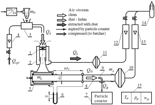
For the purpose of the study, a cylindrical test filter element () was prepared from each filter medium. The paper surface area Ap and non-woven fabric surface area Aw were selected to ensure that the condition of an allowable (maximum) filtration rate υFdop ≤ 0.06 m/s was met at the maximum air stream flow rate for a cyclone QG resulting from the engine’s air demand QNs at a speed corresponding to the maximum engine power nN. A single flow-through cyclone with an internal diameter D of 35 mm (), internal diameter of the inlet opening of its outlet port dw of 23.4 mm and total length H of 124 mm was used as the first stage of the “filter set.” Air turbulence was forced using four guide vanes.
Figure 3. Functional diagram of the test stand for testing filter media in the “cyclone–panel filter” configuration: 1–cyclone, 2–dust collector, 3–dust dispenser, 4–compressed air rotameter, 5–tested filter element, 6–liquid pressure gauge, 7–particle counter, 8–duct, 9–dust probe, 10–absolute rated filter—main line, 11–absolute rated filter—extraction line, 12–extraction stream rotameter, 13–main stream rotameter, 14–extraction fan, and 15–ambient temperature, pressure, and air humidity gauge.
The filtration efficiency, filtration performance, and pressure drop of the two filter elements with different properties used as the second filtration stage (downstream of the flow-through cyclone) of the “filter set” and without a cyclone were determined as follows at a constant filtration rate υF of 0.06 m/s:
Separation efficiency φ = f(km),
Filtration performance dzmax = f(km),
Pressure drop Δp = f(km).
The tests were conducted until the filter element reached the allowable pressure drop Δpdop of 5 kPa.
5. Test methods and conditions
To determine the mass loading of dust km, the mass of the dust mcw retained over 1 m2 of the filter medium (paper or non-woven fabric) before the allowable pressure drop Δpfdop is reached must be known. Tests were performed on a test stand (). The test stand included a Pamas-2132 particle counter with an HCB-LD-2A-2000-1 sensor, which was used to determine the number and size of dust particles in the air stream downstream of the tested filter element. The measurement range was 0.7–100 µm, which was divided into 32 measurement intervals by (dzmin–dzmax) diameters. The device sensor can detect particles up to a maximum particle concentration in the air of 1,000/ml, corresponding to a mass dust concentration s of ∼0.25 g/m3.
The duct was also fitted with an absolute rating filter to simultaneously protect the rotameter against dust ingress and determine the dust mass mA flowing through the filter element and, consequently, its separation efficiency φ.
The dust retained by the cyclone is transferred to the dust collector and removed by the ejection dust removal system. The intensity of dust extraction from the cyclone’s dust collector can be expressed as the extraction rate m0, defined as the ratio of the air stream flow rate QS in the extraction system to the air stream flow rate QG at the cyclone outlet. A dust extraction rate m0 of 8% was used for the cyclone’s dust collector during the tests.
The filtration parameters of the tested filter media were determined using a gravimetric method (to determine the masses of retained and supplied dust) in subsequent j measurement cycles at specific intervals. PTC-D test dust, which is equivalent to AC-fine test dust, was used. The chemical composition and particle-size distribution of the test dust in ISO 12103, part 1: arizona test dust (PN-ISO 5011. Citation1994).
During the tests of the “filter set,” the dust concentration at the cyclone inlet was s = 1 g/m3. During the tests of the panel filter (filter element), the concentration was s = 0.5 g/m3.
The tests were conducted for j measurement cycles with a duration (uniform dust batching time) of τp = 180 s in the initial period. The duration of the measurement cycle τp was increased four times in the main operation period. After each measurement cycle j, the filtration efficiency, filtration performance, pressure drop, and mass loading of dust were determined for the filter element.
The pressure drop Δp was determined from the drop in static pressure at the outlet line at a distance of 6dw from the filter element outlet edge based on the U-tube manometer Δhj (mm H2O) readouts using the following relationship:
(4)
Where: rm – manometric liquid density [kg/m−3], rH – air density [kg/m−3], and g – gravity acceleration [m/s2].
The separation efficiency of the filter element without a cyclone was determined after each jth measurement cycle as the ratio of the dust mass mZj retained in time τp by the filter element to the dust mass mDj introduced uniformly to the filter element by the stream of inlet air:
(5)
The separation efficiency of the filter element used as the second filtration stage (downstream of the flow-through cyclone) was determined using the following relationship:
(6)
where mAj is the dust mass retained by the absolute rated filter during time τp of a subsequent measurement cycle j.
The filtration performance of the filter element was determined based on the measurements of the number and size of dust particles, with the largest dust particles dz = dzmax in a single test cycle present in the air stream downstream of the filter element.
The mass loading of dust kmj was calculated using the following formula:
(7)
6. Analysis of the test results
The service life of the filter element could be divided into two periods based on filtration efficiency. The first period (Ip, IZp—, Iw, IZw—) was characterized by low filtration efficiency, which systematically and rapidly increased as the mass of dust retained by the filter paper (non-woven fabric) increased, which in turn increased the mass loading of dust km.
Figure 4. The properties of the filter paper used as the second filtration stage of the filter set (downstream of the flow-through cyclone) and in a single-stage system: (a) separation efficiency φp = f(km) and pressure drop Δpp = f(km); (b) separation efficiency φp = f(km) and filtration performance dzmax = f(km) as a function of the mass loading of dust km.
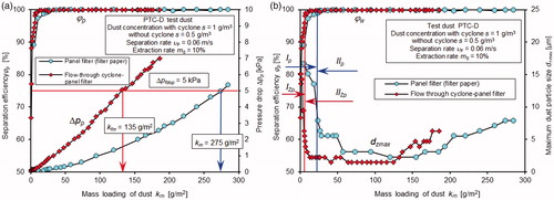
Figure 5. The properties of the non-woven fabric used as the second filtration stage of the “filter set” (downstream of the flow-through cyclone) and in a single-stage system: (a) separation efficiency φw = f(km) and pressure drop Δpw = (km); (b) separation efficiency φw = f(km) and filtration performance dzmax = f(km) as a function of the mass loading of dust km.
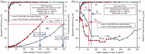
The initial filtration period lasted from the beginning of the filtration process until the maximum separation efficiency of the filter paper (non-woven fabric) was reached. The changeover between filtration periods was observed at a separation efficiency φ of 99.5% (EquationEquation (1)(1) ). The main filtration period (IIp, IIZp) was characterized by stable separation efficiency φ of 99.5–99.98% and a constantly increasing pressure drop (). After the first measurement cycle, the separation efficiency of the filter paper element was φp1 = 89% without a cyclone and φp2 = 66% with a cyclone (). The initial filtration efficiencies of the non-woven fabric were φw1 = 93% and φw2 = 78%, respectively ().
In the initial filtration period, the maximum dimension of dust particles (flowing through the filter element) in the air downstream of the filter paper (without a cyclone) was dzmax = 16.7 µm, whereas the maximum dimension of dust particles downstream of the non-woven fabric was dzmax = 22 µm. As the mass loading of dust km increased, the dust particle diameters dzmax decreased, and for the paper element without a cyclone, the values stabilized at dzmax = 5.5 µm after reaching km = 28.5 g/m2. With a cyclone, the average values stabilized at a lower level (dzmax = 2.3 µm) and significantly earlier, at km = 12.7 g/m2.
Similar effects were observed for the non-woven fabric; however, the dust particle diameter dzmax stabilized at a slightly higher level and at higher mass loading of dust km compared to the filter paper. The initial filtration period of the non-woven fabric filter (Iw, Izw) was longer. After the non-woven fabric without a cyclone reached a km of 72.2 g/m2, the air contained dust particles with a diameter dzmax of 6.2 µm, whereas the diameters stabilized at a dzmax of ∼3.8 µm for the filter element with a cyclone.
Once the dust particles with the maximum dimension of dzmax were stabilized, the main (stable) operation period of the filter element commenced, ending when the allowable pressure drop Δpfdop of 5 kPa was reached.
The initial dust particles retained by the panel filter acted as a source of secondary structural elements, as indicated by the shapes of the filtration performance and pressure drop curves. Dust particles can be retained not only by fibers but also by previously retained particles. Bulky agglomerates that fill voids form between the fibers and retain increasingly smaller dust particles, simultaneously reducing the aerosol flow and increasing the pressure drop as the dust mass retained by the filter element increases.
A simple explanation of this effect is not easy to provide since the aerosol filtration process is stochastic in nature and difficult to quantify and qualify. The particle retention process in a porous panel filter depends on many forces and phenomena. The particles and elements of the porous medium are irregularly shaped, with an irregular surface microstructure. The dust particles settle uniformly on the fiber surfaces. The porosity of the panel filter is reduced, and the retained particles can be trapped by the flowing stream of air.
The pressure drop Δp of the tested filter elements increased gradually as the mass loading of dust km increased. For the filter paper without a cyclone, Δpp was 5 kPa at an mass loading of dust km of 285 g/m2; with the cyclone, the mass loading of dust km was 50% lower, 132.3 g/m2.
The pressure drop Δp, a criterion for replacement of the filter element, increased more rapidly when the panel filter was subjected to dust whose particle size distribution was modified by the cyclone due to the resultant variation of effects and filtration mechanisms. The dust did not contain any large particles with diameters >25–35 µm.
Filters clog more quickly when loaded with smaller aerosol particles (Walsh and Stenhouse Citation1997). As dendrites grow more quickly when filter samples are loaded with smaller particles, they become clogged at lower mass deposits, and the mechanical contribution to the separation efficiency becomes significant more at an earlier degree of deposition; so penetration reaches a maximum more quickly. Further, a cake forms at the surface more quickly and thus the penetration falls to zero more quickly with smaller particles.
Experimental test results ( and ) are showing faster fiber filters pressure drop increase for small particles, which also confirmed model tests results obtained by the authors: Saleh et al. (Citation2014, Citation2015), Saleh and Tafreshi (Citation2014), Fotovati et al. (Citation2011), Thomas et al. (Citation2001), Cheng and Tsai (Citation1998), Jaroszczyk (Citation1987), Poon and Liu (Citation1997). Model tests were carried out with usage of monodisperse and polydispersed dust with grain diameters in the range of 1 μm ÷ 10 μm
It depends on the particles size, capture mechanisms, and the filter structure. Fine particles are more clogging than coarse particles because they have higher surface area to volume ratios ag. Thus they have higher drag and pressure drop per unit volume/mass of particles. The collection mechanism affects the structure of the particles deposits. Particles collected by diffusion and interception are more clogging because they form dendritic particles structures. The tree-like dendrites expose more particles to the flow, resulting in higher pressure drops. Particles collected by impaction form a closely packed deposit. Fewer particles are exposed to the flow and the resulting flow resistance is lower.
Mineral dust grains have an irregular shape, and therefore theoretical considerations assume the shape of a sphere with equivalent diameter. The phenomenon of pore tight filling in filter paper by small-particle dust particles can be explained by the example of two dust deposits. One bed made up of spherical particles with small ones and the other with large sizes. The model of the bed formed from regularly arranged spheres was taken into consideration. A section of such deposit in the form of a cube with a side d is shown in , where d is also the diameter of the sphere. The porosity of such deposit does not depend on particle diameter and equals:
(8)
where V = d3—cube volume. ε ≈ 0.48 = 48%
Figure 6. Bed model of similar spherical particles.
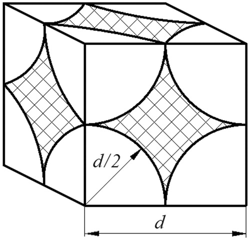
V1 = volume of the space between the particles equals the volume of the cube V minus the volume occupied by the particles V2 according to the equation:
(9)
(10)
From the above equation, we can assume that volume of space between particles V1 depends on the diameter of the particles d in the third power. V1 volume between consecutive particles forms a channel (conventionally noted by diameter dε), in which air flows. For smaller and smaller particle diameters d, the volume between V1 particles becomes smaller and smaller.
The volume of space between V1 particles with equivalent diameter d = 80 μm has the value V1(80) = 244,053 µm3. The volume of space between V1 particles with equivalent diameter d = 40 μm has a value V1(40) = 30,506 µm3, so eight times less than for d = 80 μm. For d = 20 μm—the value of V1(20) is 64 times smaller. For d = 8 μm—V1(8) is 1000 times lower than for d = 80 μm, and for d = 2 μm—V1(2) is 64,000 times smaller.
For the same value of the air flow Q (filtration rate υF) flowing through the filter bed formed of particles of smaller and smaller diameters, the actual velocity υε in the channels between the particles assumes increasing values. Therefore, the pressure drop Δp of the filter bed will assume increasing values in accordance with the modified Darcy’s, Weisbach’s equation.
(11)
where ρ—fluid density, λ—friction coefficient, gw—filter bed thickness, dε—contractual channel diameter created by the particles, υε—the actual velocity in the channels between the particles.
The curves show that the inertial filter as the first filtration stage retained larger particles (>25–35 µm), while small particles passed through the filter, reducing the dust capacity of the filter paper used as the second filtration stage. The analysis of the separation efficiency and pressure drop as a function of dust mass in the inlet air () shows that the service life of the “cyclone–porous panel” system until the allowable pressure drop Δpdop = 5 kPa was reached was ∼100% longer than that of the filter paper without a cyclone, validating the filtration properties of the system.
Figure 7. The characteristics of separation efficiency φw = f(km) and pressure drop Δpw = f(km) as a function of dust mass in the inlet air of the filter paper used as the second filtration stage of the “filter set” (downstream of the flow-through cyclone) and in the single-stage filtration system.
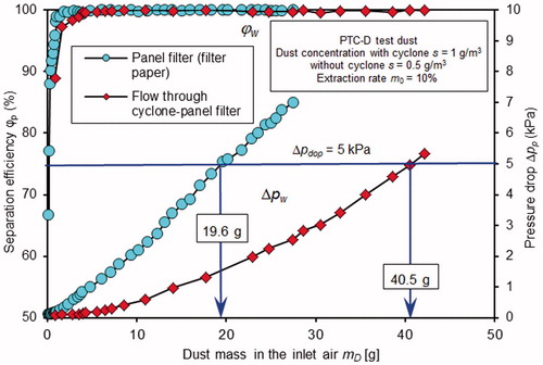
When a cyclone was used as the first filtration stage upstream of the filter paper, most of the supplied dust (∼80% of the dust mass for the tested filter set) was retained by the cyclone. The filter element retained 20% of the dust mass introduced to the “cyclone–panel filter” system.
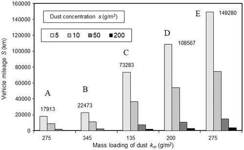
shows the predicted mileage (for various dust concentrations in the air) for a truck with a Vss = 12.88 dm3 internal combustion engine with a supercharged air cooler with a single-stage filtration system (filter paper or non-woven fabric) or a two-stage filtration system (cyclone–filter paper or cyclone–non-woven fabric).
Figure 8. Predicted mileage of a vehicle fitted with a single-stage or two-stage filtration system: A–paper, B–non-woven fabric, C–cyclone–paper, D–cyclone: non-woven fabric, E–cyclone–paper.
Dust mass loading km by the filter material is defined as the average dust mass per unit of filtration area. It was also assumed that the dust is evenly deposited on the entire active surface. The above assumption was taken based on conditions of experimental research, during which dust mass loading km was determined. Laboratory tests were carried out at a constant filtration rate υF = 0.06 m/s, and constant concentration of dosed dust to the filter s = 0.5 g/m3. The polydispersive test dust PTC-D (AC-fine) was dosed evenly in test cycles with a duration of t = 180 s and 360 s.
The mass loadings of dust km for the filter paper and non-woven fabric were used in the calculations. The predicted mileage is 18,000 km or 22,500 km for a vehicle fitted with a single-stage filtration system using filter paper or non-woven fabric, respectively, at a dust concentration s of 5 mg/m3. When the same filter elements are used in a two-stage filtration system (downstream of the multicyclone), the vehicle mileage improves significantly: SII = 73,000 km and SII = 108,000 km, respectively, after reaching the allowable pressure drop Δpdop of 5 kPa. The greater mileage of the vehicle fitted with the non-woven fabric filter element in the single-stage or two-stage filtration system is due to the greater thickness of the non-woven fabric (g = 2.34 mm) compared to the filter paper (g = 0.56 mm). The lower the dust concentration in the air, the greater the predicted vehicle mileage.
At a dust concentration s of 5 mg/m3 and filter paper mass loading of dust km of 275 g/m2, selecting two-stage filtration for the truck’s engine doubles the predicted vehicle mileage to SII = 150,000 km compared to single-stage filtration (). The vehicle mileage determined using this method is incorrect and misleading.
Author is aware of the fact that the nonuniformity of particle deposition in the filter occurs, but the aim of the study was to show that the coefficient km has much smaller (two to four times) value, when for porous partition (filter paper, nonwoven) flows air with fine dust. Such situation occurs in the two-stage car air filtration system “multicyclone–porous partition.” Therefore, the filter obtains the value of Δpfdop much earlier, and for a smaller mass of retained dust. This has a direct effect on the filter’s working time, and thus on the vehicle mileage. Assuming constant value of km coefficient during simulation of vehicle mileage () is an approximation of which the author is aware of. Less important to the author is the unevenness of particle deposition in the filter.
7. Conclusions
The developed method permits the determination of the basic characteristics of filter media used as a second filtration stage with a wide range of structural parameters and changes in filtration conditions corresponding to air filter operation at high dust concentrations.
The developed method is unconventional as the filter medium is subjected to dust with a chemical composition and particle-size distribution modified by the actual filtration process in the cyclone.
Using filter media in a “multicyclone–porous panel filter” configuration results in an mass loading of dust that is two to four times lower than that achieved using the same media in a single-stage filtration system due to differences in the particle-size distribution of the dust. This lower mass loading of dust directly affects the service life until the allowable flow rate is reached and, consequently, vehicle mileage.
A low separation efficiency (φ = 55–77%) of the filter medium and a large particle size (dzmax = 14 μm) in the air in an initial, short period of operation may result in accelerated wear of the pistons, piston rings and cylinder liners.
| Nomenclature | ||
| Ac | = | active filter paper area (m2) |
| b | = | pleat height (m) |
| dw | = | fiber diameter (µm) |
| dz | = | dust particle diameter (µm) |
| g | = | gravity acceleration (m/s2) |
| gw | = | filter bed thickness |
| h | = | pleat width (m) |
| ip | = | no. of pleats |
| kc | = | coefficient corresponding to the differences in parameters between test dust particles and actual dust particles |
| km | = | filter paper mass loading of dust (kg⋅m–2) |
| kzp | = | dust particle shape |
| mp | = | mass of retained dust (kg) |
| p | = | ambient pressure (Pa) |
| s | = | dust concentration at the filter inlet (g⋅m–3) |
| t | = | ambient air temperature (°C) |
| QNs | = | nominal air demand of the engine (kg⋅s–1) |
| w | = | ambient air humidity (%) |
| Greek symbols | ||
| ρzp | = | dust particle density (kg⋅m–3) |
| ρ | = | fluid density (kg⋅m–3) |
| ρm | = | manometric liquid density (kg/m–3) |
| ρH | = | air density (kg/m–3) |
| ε | = | Porosity (%) |
| υF | = | air flow rate through the filter layer–filtration rate (m⋅s–1) |
| υε | = | the actual velocity in the channels between the particles (m⋅s–1) |
| λ | = | friction coefficient |
| μ | = | ambient air viscosity (kg⋅m–1⋅s–1) |
| τ | = | filter service life from replacement (s) |
| Δpfdop | = | allowable pressure drop (Pa) |
| φm | = | multicyclone separation efficiency (%) |
| φp | = | filter paper separation efficiency (%) |
References
- Baltrėnas, P., and A. Chlebnikovas. 2015. Experimental Research on the Dynamics of Airflow Parameters in a Six-Channel Cyclone-Separator. Powder Technol. 283:328–33. doi:10.1016/j.powtec.2015.06.005.
- Barris, M. A. 1995. Total Filtration TM. The Influence of Filter Selection on Engine Wear, Emissions, and Performance. SAE Technical Paper Series 952557.
- Bugli, N. J. 2000. Service Life Expectations and Filtration Performance of Engine Air Cleaners. SAE Tech. Paper Ser. 2000:01–3317.
- Bugli, N. 2001. Automotive Engine Air Cleaners—Performance Trends. SAE Tech. Paper 2001:01–1356.
- Caesar, T., and T. Schroth. 2002. The Influence of Pleat Geometry on the Pressure Drop in Deep–Pleated Cassette Filters. Filtr. Sep. 39 (9):48–54. doi:10.1016/S0015-1882(02)80247-6.
- Chen, X., and T. D. Papathanasiou. 2006. On the Variability of the Kozeny Constant for Saturated Flow Across Unidirectional Disordered Fiber Arrays. Compos. Part A 37 (6):836–46. doi:10.1016/j.compositesa.2005.01.018.
- Chen, D. R., D. Y. H. Pui, and B. Y. H. Liu. 1995. Optimization of Pleated Filter Designs Using a Finite-Element Numerical Model. Aerosol Sci. Technol. 23 (4): 579–90. doi:10.1080/02786829508965339.
- Cheng, Y. H., and C.-J. Tsai. 1998. Factors Influencing Pressure Drop Through a Dust Cake During Filtration. Aerosol Sci. Technol. 29 (4): 315–28.
- Clague, S., and R. J. Phillips. 1997. A Numerical Calculation of the Hydraulic Permeability of Three-Dimensional Disordered Fibrous Media. Phys. Fluids 9 (6): 1562–72. doi:10.1063/1.869278.
- Del Fabbro, L., J. C. Laborde, P. Merlin, and L. Ricciardi. 2002. Air Flows and Pressure Drop Modeling for Different Pleated Industrial Filters. Filtr. Sep. 39 (1): 34–40. doi:10.1016/S0015-1882(02)80055-6.
- Dhaniyala, S., and B. Y. H. Liu. 1999. An Asymmetrical, Three-Dimensional Model for Fibrous Filters. Aerosol Sci. Technol. 30 (4): 333–48. doi:10.1080/027868299304543.
- Durst, M., G. Klein, and N. Moser. 2005. Filtration in fahrzeugen. Mann + hummel GMBH. Ludwigsburg, Germany: Mann + Hummel GMBH.
- Dziubak, T. 2017. Problems of Dust Removal from Multicyclones of Engine Air Cleaners in Cross-Country Motor Vehicles. Arch. Autom. Eng. 76: 37–62. doi:10.14669/AM.VOL76.ART2.
- Dziubak, T., and S. Szwedkowicz. 2015. Operating Properties of Non-woven Fabric Panel Filters for Internal Combustion Engine Inlet Air in Single and Two-Stage Filtration Systems. EiN 17 (4): 519–27. doi:10.17531/ein2015.4.6.
- Dziubak, T., and S. Szwedkowicz. 2013a. Experimental Research of Axial Cyclones of Combustion Engines Air Filters. Bull. Military Univ. Technol. 2: 201–17.
- Dziubak, T., and S. Szwedkowicz. 2013b. Experimental Research of Filtration Paper Operating in Cyclone-Porous Barrier System. Bull. Military Univ. Technol. 1: 271–86.
- Dziubak, T. 2000. The Problems of the Filtration in the Vehicle Engines Exploitated in Large Pollution Conditions. Exploit. Prob. Mach. Polish Acad. Sci. 124: 181–97.
- Dziubak, T. 2006. Modification of Returnable Cyclone with a Tangent Inlet Construction. Bull. Military Univ. Technol. 2: 279–301.
- Erdmannsdörfer, H. 1971. Leistungsmöglichkeiten von papierfiltern zur reinigung der ansaugluft von diselmotoren. MTZ 32: 123–31.
- Feng, Z., Z. Long, and Q. Chen. 2014. Assessment of Various CFD Models for Predicting Airflow and Pressure Drop through Pleated Filter System. Build. Environ. 75: 132–41. doi:10.1016/j.buildenv.2014.01.022.
- Filippova, O., and D. Hanel. 1997. Lattice–Boltzmann simulation of gas-particle flow in filters. Comput. Fluids 26 (7): 697–712. doi:10.1016/S0045-7930(97)00009-1.
- Fotovati, S., H. V. Tafreshi, and B. Pourdeyhimi. 2010. Influence of Fiber Orientation on Performance of Aerosol Filtration Media. Chem. Eng. Sci. 65 (18): 5285–93. doi:10.1016/j.ces.2010.06.032.
- Fotovati, S., S. A. Hosseini, H. Vahedi Tafreshi, and B. Pourdeyhimi. 2011. Modeling Instantaneous Pressure Drop of Pleated Thin Filter Media During Dust Loading. Chem. Eng. Sci. 66 (18): 4036–46. doi:10.1016/j.ces.2011.05.038.
- Fotovati, S., H. V. Tafreshi, and B. Pourdeyhimi. 2012. A Macroscale Model for Simulating Pressure Drop and Collection Efficiency of Pleated Filters Over Time. Sep. Purif. Technol. 98: 344–55. doi:10.1016/j.seppur.2012.07.009.
- Grafe, T., M. Gogins, M. Barris, J. Schaefer, and R. Canepa. 2001. Nanofibers in Filtration Applications in Transportation. Paper presented at Filtration 2001 International Conference and Exposition of the INDA, Chicago, Illinois, December 3–5.
- Haig, C. W., A. Hursthouse, S. McIlwain, and D. Sykes. 2014. The Effect of Particle Agglomeration and Attrition on the Separation Efficiency of a Stairmand Cyclone. Powder Technol. 258: 110–24. doi:10.1016/j.powtec.2014.03.008.
- Higdon, J. J. L., and G. D. Ford. 1996. Permeability of Three-Dimensional Models of Fibrous Porous Media. J. Fluid. Mech. 308 (1): 341–61. doi:10.1017/S0022112096001504">10.1017/S0022112096001504.
- Hosseini, S. A., and H. V. Tafreshi. 2010. Modeling Permeability of 3-D Nanofiber Media in Slip Flow Regime. Chem. Eng. Sci. 65 (6): 2249–54. doi:10.1016/j.ces.2009.12.002.
- Hosseini, S. A., and H. V. Tafreshi. 2010. Modeling Particle Filtration in Disordered 2-D Domains: A Comparison with Cell Models. Sep. Purif. Technol. 74 (2): 160–69. doi:10.1016/j.seppur.2010.06.001.
- Hosseini, S. A., and H. V. Tafreshi. 2010. 3-D simulation of Particle Filtration in Electrospun Nanofibrous Filters. Powder Technol. 201 (2): 153–60. doi:10.1016/j.powtec.2010.03.020.
- Hosseini, S. A., and H. V. Tafreshi. 2012. Modeling Particle-Loaded Single Fiber Efficiency and Fiber Drag Using ANSYS-Fluent CFD Code. Comput. Fluid. 74: 157–66. doi:10.1016/j.compfluid.2012.06.017.
- Jackson, G., and D. James. 1986. The Permeability of Fibrous Porous Media. Can. J. Chem. Eng. 64: 364–75. doi:10.1002/cjce.5450640302.
- Jaganathan, S., H. V. Tafreshi, and B. Pourdeyhimi. 2008. A Case Study of Realistic Two-Scale Modeling of Water Permeability in Fibrous Media. Sep. Sci. Technol. 43 (8): 1901–16. doi:10.1080/01496390802063960.
- Jaroszczyk, T. 1987. Air Filtration in Heavy-Duty Motor Vehicle Applications. Paper presented at the Proceedings of the Dust Symposium III Vicksburg MS, September 15–17.
- Jaroszczyk, T., and T. Ptak. 1985. Experimental Study of Aerosol Separation Using a Minicyclone. Paper presented at 10th Annual Powder and Bulk Solids Conference. O’Hare Expo Center Rosemont, Illinois, May 7–9.
- Kanaoka, C., S. Hiragi, and W. Tanthapanichakoon. 2001. Stochastic Simulation of the Agglomerative Deposition Process of Aerosol Particles on an Electret Fiber. Powder Technol. 118 (1-2): 97–106. doi:10.1016/S0032-5910(01)00299-6.
- Kim, H., B. Han, Y. Kim, T. Oda, and H. Won. 2013. Submicrometer Particle Removal Indoors by a Novel Electrostatic Precipitator with High Clean Air Delivery Rate, Low Ozone Emissions and Carbon Fiber Ionizer. Indoor Air 23 (5): 369–78. doi:10.1111/ina.12037.
- Kanaoka, C., H. Emi, and T. Myojo. 1980. Simulation of the Growing Process of a Particle Dendrite and Evaluation of a Single Fibre Collection Efficiency with Dust Load. J. Aerosol Sci. 11 (4): 377–89. doi:10.1016/0021-8502(80)90046-4.
- Koponen, A., D. Kandhai, E. Hellén, M. Alava, A. Hoekstra, M. Kataja, K. Niskanen, P. Sloot, and J. Timonen. 1998. Permeability of Three Dimensional Random Fiber Webs. Phys. Rev. Lett. 80 (4): 716–19. doi:10.1103/PhysRevLett.80.716.
- Lantermann, U., and D. Hänel. 2007. Particle Monte Carlo and Lattice-Boltzmann Methods for Simulations of Gas-Particle Flows. Comput. Fluid. 36 (2): 407–22. doi:10.1016/j.compfluid.2005.10.005.
- Li, J., S. Li, and F. Zhou. 2015. Effect of Cone Installation in a Pleated Filter Cartridge During Pulse-Jet Cleaning. Powder Technol. 284: 245–52. doi:10.1016/j.powtec.2015.06.071.
- Li, S. Q., and J. S. Marshall. 2007. Discrete Element Simulation of Micro-Particle Deposition on a Cylindrical Fiber in an Array. J. Aerosol Sci. 38 (10): 1031–46. doi:10.1016/j.jaerosci.2007.08.004.
- Lo, L. M., D. R. Chen, and D. Y. Pui. 2010. Experimental Study of Pleated Fabric Cartridges in a Pulse-Jet Cleaned Dust Collector. Powder Technol. 197 (3): 141–49. doi:10.1016/j.powtec.2009.09.007.
- Lo, L. M., S. C. Hu, D. R. Chen, and D. Y. H. Pui. 2010. Numerical Study of Pleated Fabric Cartridges During Pulse–Jet Cleaning. Powder Technol. 198 (1): 75–81. doi:10.1016/j.powtec.2009.10.017.
- Lücke, T., and H. Fissan. 1996. The Prediction of Filtration Performance of High Efficiency Gas Filter Elements. Chem. Eng. Sci. 51 (8): 1199–208. doi:10.1016/0009-2509(95)00366-5.
- Mahowald, N., S. Albani, J. F. Kok, S. Engelstaeder, R. Scanza, D. S. Ward, and M. G. Flanner. 2014. The Size Distribution of Desert Dust Aerosols and Its Impact on the Earth System. Aeolian Res. 15: 53–71. doi:10.1016/j.aeolia.2013.09.002
- Melzer, H. H., and W. Brox. 1984. Ansauggerauschdampfer und luftfilter für BMW 524 td. MTZ 45: 223–27.
- Payatakes, A. C., and L. Gradoń. 1980. Dendritic Deposition of Aerosols by Convective Brownian Diffusion for Small, Intermediate and High Particle Knudsen Numbers. AIChE J. 26 (3): 443–54. doi:10.1002/aic.690260316.
- Payatakes, A. C., and C. Tien. 1976. Particle Deposition in Fibrous Media with Dendrite-Like Pattern: a Preliminary Model. J. Aerosol Sci. 7(2):85–100. doi:10.1016/0021-8502(76)90067-7.
- PN-ISO 5011. 1994. Air filters for internal combustion engines and compressors. Research and activities, PKN.
- Poon, W. S., and B. Y. H. Liu. 1997. Dust loading behavior of engine and general purpose air cleaning filters. SAE 970676, international congress & exposition. Detroit, Michigan.
- Rebai, M., M. Prat, M. Meireles, P. Schmitz, and R. Baclet. 2010. Clogging Modeling in Pleated Filters for Gas Filtration. Chem. Eng. Res. Des. 88 (4): 476–86. doi:10.1016/j.cherd.2009.08.014.
- Rivera, B. H., and M. G. Rodriguez. 2016. Characterization of Airborne Particles Collected from Car Engine Air Filters Using SEM and EDX Techniques. Int. J. Environ. Res. Public Health 13 (10): 985. doi:10.3390/ijerph13100985.
- Saleh, A. M., H. V. Tafreshi, and B. Pourdeyhimi. 2015. Service Life of Circular Pleated Filters vs. that of Their Flat Counterpart. Sep. Purif. Technol. 156: 881–88. doi:10.1016/j.seppur.2015.09.041.
- Saleh, A. M., and H. V. Tafreshi. 2014. A Simple Semi-numerical Model for Designing Pleated Air Filters Under Dust Loading. Sep. Purif. Technol. 137: 94–108. doi:10.1016/j.seppur.2014.09.029.
- Saleh, A. M., S. Fotovati, H. V. Tafreshi, and B. Pourdeyhimi. 2014. Modeling Service Life of Pleated Filters Exposed to Poly-Dispersed Aerosols. Powder Technol. 266: 79–89. doi:10.1016/j.powtec.2014.06.011.
- Saleh, A. M., S. A. Hosseini, H. V. Tafreshi, and B. Pourdeyhimi. 2013. 3-D Microscale Simulation of Dust-Loading in Thin Flat-Sheet Filters: A Comparison with 1-D Macroscale Simulations. Chem. Eng. Sci. 99: 284–91. doi:10.1016/j.ces.2013.06.007.
- Sanders, R., A. Bühler, M. Durst, N. Moser, and A. Pelz. 2007. Effiziente motorluftfiltration durch den einsatz von nanofasern. MTZ 68 (2): 112–118.
- Schaeffer, J. W., and L. M. Olson. 1998. Air Filtration Media for Transportation Applications. Filtr. Sep. 35 (2): 124–29.
- Schulze, M., and G. Taufkirch. 1991. Papierluftfilter nutzfahrzeugen. Rechnerische zur bestimmung spezifischer kennwerte und standzeit-Vorausberechnungen. MTZ 52: 598–607.
- Spielman, L., and S. L. Goren. 1968. Model for Predicting Pressure Drop and Separation Efficiency in Fibrous Media. Environ. Sci. Technol. 2 (4): 279–87.
- Subrenat, A., J. Bellettre, and P. L. Cloirec. 2003. 3D Numerical Simulations of Flows in a Cylindrical Pleated Filter Packed with Activated Carbon Cloth. Chem. Eng. Sci. 58 (22): 4965–73. doi:10.1016/j.ces.2003.07.012.
- Tafreshi, H. V., M. S. Rahman, S. Jaganathan, Q. Wang, and B. Pourdeyhimi. 2009. Analytical Expressions for Predicting Permeability of Bimodal Fibrous Porous Media. Chem. Eng. Sci. 64 (6): 1154–59. doi:10.1016/j.ces.2008.11.013.
- Tahir, M. A., and H. V. Tafreshi. 2009. Influence of Fiber Orientation on the Transverse Permeability of Fibrous Media. Phys. Fluid. 21 (8): 083604–083605. doi:10.1063/1.3211192.
- Taufkirch, G., and G. Mayr. 1984. Papierluftfilter für motoren in nutzfahrzeugen. MTZ 45: 95–105.
- Théron, F., A. Joubert, and L. L. Coq. 2017. Numerical and Experimental Investigations of the Influence of the Pleat Geometry on the Pressure Drop and Velocity Field of a Pleated Fibrous Filter. Sep. Purif. Technol. 182: 69–77. doi:10.1016/j.seppur.2017.02.034.
- Thomas, D., P. Penicot, P. Contal, D. Leclerc, and J. Vendel. 2001. Clogging of Fibrous Filters by Solid Aerosol Particles Experimental and Modelling Study. Chem. Eng. Sci. 56 (11): 3549–61.
- Tien, C., and B. V. Ramarao. 2013. Can Filter Cake Porosity Be Estimated Based on the Kozeny–Carman Equation? Powder Technol 237: 233–40. doi:10.1016/j.powtec.2012.09.031.
- Tung, K. L., Y. L. Li, K. T. Lu, and W. M. Lu. 2006. Effect of Calendering of Filter Cloth on Transient Characteristics of Cake Filtration. Sep. Purif. Technol. 48 (1): 1–15. doi:10.1016/j.seppur.2005.07.026.
- Tronville, P., and R. Sala. 2003. Minimization of Resistance in Pleated–Media Air Filter Design: Empirical and CFD Approach. HVAC&Res. 9 (1): 95–106. doi:10.1080/10789669.2003.10391058.
- Yan, C., G. Liu, and H. Chen. 2013. Effect of Induced Airflow on the Surface Static Pressure of Pleated Fabric Filter Cartridges during Pulse Jet Cleaning. Powder Technol. 249: 424–30. doi:10.1016/j.powtec.2013.09.017.
- Yang, J., W. G. Sun, and C. Gao. 2013. Effect of the Inlet Dimensions on the Maximum-Efficiency Cyclone Height. Sep. Purif. Technol. 105: 15–23. doi:10.1016/j.seppur.2012.12.020.
- Waghode, A. N., N. S. Hanspal, R. J. Wakeman, and V. Nassehi. 2007. Numerical Analysis of Medium Compression and Losses in Filtration Area in Pleated Membrane Cartridge Filters. Chem. Eng. Commun. 194 (8): 1053–64. doi:10.1080/00986440701293140.
- Wang, Q., B. Maze, H. V. Tafreshi, and B. Pourdeyhimi. 2006. A Case Study of Simulating Submicron Aerosol Filtration via Lightweight Spun-Bonded Filter Media. Chem. Eng. Sci. 61 (15): 4871–83. doi:10.1016/j.ces.2006.03.039.
- Wang, Q., B. Maze, H. V. Tafreshi, and B. Pourdeyhimi. 2007. Simulating through plane permeability of fibrous materials with different fiber lengths. Model. Simul. Mater. Sci. Eng. 15 (8): 855–68. doi:10.1088/0965-0393/15/8/003.
- Wakeman, R. J., N. S. Hanspal, A. N. Waghode, and V. Nassehi. 2005. Analysis of Pleat Crowding and Medium Compression in Pleated Cartridge Filters. Chem. Eng. Res. Des. 83 (10): 1246–55. doi:10.1205/cherd.04183.
- Walsh, D. C., and J. I. T. Stenhouse. 1997. The Effect of the Size of the Loading Particles on These Points Is Explained by the Rate of Dendritic Growth, and Ultimately Filter Clogging, Under the Different Loading Conditions. J. Aerosol Sci. 28 (2): 307–21.
- WIX Filtron, Filter catalog, Gostyń, 2017. www.retopfibre.en.alibaba. 25.05.2017.
- Zobel, S., B. Maze, H. V. Tafreshi, Q. Wang, and B. Pourdeyhimi. 2007. Simulating Permeability of 3-D Calendered Fibrous Structures. Chem. Eng. Sci. 62 (22): 6285–96. doi:10.1016/j.ces.2007.07.007.