
Abstract
Transmission electron microscopy of soot aggregates is performed using a tilting-stage with view angles from –60 to +50 degrees. The resulting series of images was used to produce videos and solid models to aid in the visualization of the structure. The images from 31 angles for each aggregate were analyzed using various 2D image processing techniques. It was found that the measurements of primary particle size varied by less than 16% as angles changed. Projected area measurements only varied by 6% as viewing angle changed. These variations are comparable to the errors expected from the image processing. Practically, 2D images are adequate for determining primary particle size and projected area with little noise or bias introduced by random projection angles. In addition, it was found that most of the aggregates contained closed ring structures, implying that during aggregation, a small amount of rotation at contact points occurs. This structural feature is not apparent in 2D images and suggests that tomography may be useful in studying soot formation and aging processes.
Copyright © 2019 American Association for Aerosol Research
1. Introduction
Measuring the properties of soot aggregates is fundamental to the understanding of their impact, the prediction of emission rates and the climate forcing effects of black carbon particles (Chen et al. Citation2017). The morphology of the aggregates is one the main properties of interest for understanding the soot formation process and its impact on health and the environment (Amin, Bennett, and Roberts Citation2018). Combustion-generated soot is generally an aggregate of primary particles that exhibits a fractal-like structure. Transmission electron microscopy (TEM) remains one of the best techniques for characterizing this structure, but produces images that are two-dimensional (2D) projections of the true three-dimensional (3D) structure. Measurements of aggregate area, primary particle size, aspect ratio, and fractal dimension are prone to artifacts due to shielding or orientation biases. If images of two aggregates are found to have differing geometric properties, it is not clear how much of the discrepancy is due to true differences in the 3D structures or is simply due to orientation effects. Orientation might be biased by the collection process and procedure (Brugière et al. Citation2014), or it might be random (Chandler, Teng, and Koylu Citation2007; Tian et al. Citation2006).
A few researchers have studied the projection artifacts using computer-simulated aggregates (Lin et al. Citation1989). This has been especially useful in understanding how the fractal dimension of images is related to the true 3D fractal dimension (Farias, Köylü, and Carvalho Citation1996; Soewono and Rogak Citation2013; Wentzel et al. Citation2003), and the relationship between projected area and total surface area. However, the simulated aggregates are composed of spherical primary particles (Eggersdorfer et al. Citation2012). Despite the success of the Diffusion-Limited Cluster Aggregation model in producing soot aggregates that appear similar to 2D images of real soot, it is unclear whether the simulated soot aggregates capture all relevant structural features. Even if the simulated soot aggregate has an accurate structure, real TEM images contain noise and limited contrast, which, despite recent developments (Tian et al. Citation2007), is difficult to reproduce in simulated images.
Projection artifacts can be studied using real images from a microscope with a tilting stage. Gray et al. used two view angles to create stereographic visualizations of aggregates to facilitate accurate counting of primary particles (Gray et al. Citation1985). It was found that counting the number of primary particles in diesel aggregates was 36 ± 5% greater when using stereopsis when compared to viewing 2D TEM images. Many modern microscopes have the capability of imaging particles at many angles such that computed tomography can be used to reconstruct the 3D aggregate. A few studies have analyzed 3D images of soot or nanoparticles aggregates (Adachi, Chung, and Buseck Citation2010; Adachi et al. Citation2007; Heinson et al. Citation2016; Moran et al. Citation2018; Orhan et al. Citation2016; Pandey et al. Citation2015; Van Poppel et al. Citation2005). These studies found that properties such as geometric surface area, volume, radius of gyration and number of primary particles are substantially different for the 3D object and its 2D projection (Adachi et al. Citation2007; Okyay et al. Citation2016; Orhan et al. Citation2016; Van Poppel et al. Citation2005). However, properly calibrated processing of 2D images can be used to derive 3D quantities (De Temmerman et al. Citation2014).
Two properties that are physically important are the projected area (usually well correlated with particle drag) and primary particle diameter (central to fractal models of aggregates). Projection artifacts in these quantities have not been studied, but might exist if aggregate sampling results in strongly biased orientations. Often measurements of aggregate area and primary particle size show great scatter (e.g., Dastanpour et al. Citation2016), and it has been impossible to disaggregate the contributions to this variance from image processing artifacts, projection artifacts, and true particle-particle differences.
Also, prior work does not mention the presence or absence of structural features that cannot be detected in 2D images, such as ring structures that might form during partial restructuring of aggregates during or after growth. In fact, the first tomographic video that we obtained showed such rings, which was an important factor in pursing this research.
2. Materials and methods
2.1. Generation of soot
The soot studied here was generated at the Carleton University Vertical Flare Facility in the Energy and Emissions Research Lab. Details of the methods and the 3 fuel blends “L6,” “M6,” “H6” are described in the online supplementary information (SI). Flares had an exit velocity of 0.5 m/s and were up to 3 m tall. Detailed characterization of soot from this facility is described by Kazemimanesh et al. (Citation2019). Although it cannot be expected to represent all soot sources, it does seem to be typical in terms of the aggregate size, primary particle size, and Raman spectra.
For simplicity in the following sections the aggregates are named using letters as no trend between the soot morphology and the production conditions has been found. Measurements of effective density (mass-mobility exponent 2.55) and EC/TC ratios (>90%) confirmed that this was typical uncoated soot suitable as a model material for the purposes of the present study.
2.2. Collection of soot
Particles were collected using a portable thermophoretic sampler, developed at the University of British Columbia. Particles were deposited onto 3 mm lacey formvar/carbon copper TEM grids (01881, 200 mesh, Ted Pella). Two of the particles in this study were collected on carbon type-B copper TEM grids (01840, 200 mesh, Ted Pella). However, these grids resulted in reduced resolution due to a more limited tilt angle at higher magnifications and to the presence of a carbon film which reduced the transmittance of the beam.
2.3. Imaging
Images of the soot aggregates were taken with a High-Resolution Transmission Electron Microscope (HRTEM) (FEI Tecnai G2), located in the Bioimaging Facility at the University of British Columbia. The device allows a magnification range of up to 700 kx, a point resolution (nm) 0.27, and a flexible high tension (20, 40, 80, 120, 160, 200 kV). Images at each plane were recorded using a magnification of approximately 100 kx, depending on the soot aggregate size, and a tension of 80 kV. Each soot aggregate has been exposed to the beam for about 450 s. Previous literature references showed that shorter time can be enough to initiate an oxidation process in soot nanoparticles. Although, a higher voltage is used, 300 kV. Furthermore, changes are visible in a size range below 2 nm (Toth, Ek, and Wiinikka 2019). The TEM grid was placed on a holder, which was able to tilt from an angle of –60° to +50°. An image of the soot aggregate was taken at each rotation degree between the ranges of –60 to –20 and +20 to +50°, and at each 2° between the range of –20 and +20°. A total of 91 images each soot aggregate were taken. Nine soot aggregates were imaged.
2.4. 2D Image processing
The 2D images used to create the tomographic reconstructions were used individually to test the effect of orientation on particle measurements. Three different 2D image processing algorithms were applied. The focus of this study was the automated algorithm described by Dastanpour, Boone, and Rogak which employs the pair correlation method (PCM) for estimating average primary particle size in an aggregate (Dastanpour, Boone, and Rogak Citation2016). As a comparison another automated code employing a Hough transformation for estimating primary particle size was tested (Kook and Pickett Citation2012). Manual sizing was employed as the robust albeit tedious reference method (details in the SI). Each aggregate had approximately 90 images taken with 1–2 degree changes between images. Approximately 30 images per aggregate were analyzed with each image processing code.
2.5. Tomographic reconstruction
The 91 images taken per soot aggregate were processed using Inspect 3D (Rösner et al. Citation2007). The Simultaneous Iterative Reconstruction Technique (SIRT) was used for the volume reconstruction. SIRT is a well-established technique used for tomography (Jacob et al. Citation2018; Mendes Citation2009; Okariz et al. Citation2017). The SIRT method re-projects from the current estimation of the tomogram by adding up densities along projection lines through the tomogram, taking the difference between the original projection data and this re-projection at each pixel (Brzostowski and McMechan Citation1992). This difference shows the amount of error in the current estimation; in the next iteration the error is distributed among the pixels along the ray contributing to it (Batenburg et al. Citation2009; Brzostowski and McMechan Citation1992; Messaoudil et al. Citation2007).
2.6. Construction of a printable solid model
Z-direction image stacks were used to create a 3D model using the tomographic image processing program IMOD (Kremer et al. Citation1996). Z-direction stacks were loaded into the 3dmod tool where the “join” drawing tool was used to manually draw contours around the particle slices. Each aggregate contained between 800 and 1100 z-direction sections and approximately 1 out of 10 sections were manually contoured. Once a sufficient stack of contours has been created, the mesh tool was used to create a solid model. The model could then be exported as a .stl file. Due to the manual contouring, the models often had sharp edges which were smoothed with Amira’s surface simplification algorithm, which collapses as edges to points on the surface mesh, as long as the original surface points remain close to the triangulated surface mesh. A detailed explanation of the process used to produce the 3D printable .stl files and the final files, are contained in the SI.
3. Results
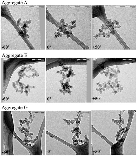
We first consider the effect of projection angle on 2D image analysis results for seven soot aggregates lettered “A” through “G”Footnote1. shows a series of three different viewing angles for three different soot aggregates illustrating substantially different morphology at different projection angles. One of the most obvious differences is the change in aspect ratio across the tilt angles.
Figure 1. Two-dimensional images of three soot aggregates at three different inclination angles. Top: aggregate A; middle: aggregate F; bottom: aggregate G.
shows the variations in primary particle diameter, projected area-equivalent diameter, and aspect ratio, with projection angle.
Figure 2. (a) Primary particle diameter is shown for seven soot aggregates (A–G). (b) Normalized area equivalent diameter is shown for seven soot aggregates (A–F, and G). (c) Particle aspect ratio is shown for seven soot aggregates (A–G).
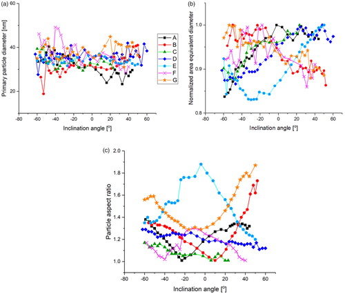
depicts only the results from the PCM method to determine average primary particle size, a graph comparing the different methods can be found in the SI. As the stage is rotated from –60° to +50°, the average primary particle size fluctuates around its mean value, but shows no correlation with angle or aspect ratio . This implies that, even if there are orientation biases in the sampling process, it is unlikely to affect the mean primary particle size. It is possible that in a larger sample or with different collection procedures a trend in particle orientation might become visible. Previous studies have suggested that thermophoresis, which was used to collect the particles studied here, can preferentially orient the particles (Brugiere et al. 2014; Mackowski Citation1990). Other studies assume thermophoresis results in random particle orientation (Chandler, Teng, and Koylu Citation2007; Tian et al. Citation2006). Likely, the magnitude of the temperature gradient (relatively small in the sampler used here) would influence such orientation biases.
shows the area-equivalent diameter normalized by the maximum area-equivalent diameter of each soot aggregate. For several aggregates, larger area is correlated with lower aspect ratio. This implies that these aggregates have a bounding envelope that is more oblate than prolate. However, not all aggregates exhibited the same behavior and given the small sample size, we do not know how typical this is. The diameters in are normalized by the maximum value so that the average must be less than unity. For most aggregates, the normalized diameter at 0 degrees is not far from the average, so we see no obvious bias with angle. The maximum variation in diameter is about 15%, corresponding to a variation in area of roughly 30%. For aggregates with uniform primary particle size, the variations in area should be indicative of the number of countable primary particles. Thus, our variations with angle appear to be lower than Gray’s earlier report that counts from 2D images were 36% too low.
summarizes the mean and standard deviation of image-derived parameters obtained by the three image processing codes. In this very small sample of aggregates we do not see an increase of primary particle diameter with projected–area, predicted by the correlation of (Dastanpour and Rogak Citation2014); this is unsurprising given that the geometric standard deviation of primary particle size around the previously reported correlation was 1.3 to 1.4.
Table 1. Image analysis results including manual, PCM, and Hough transformation algorithm comparisons given as the mean ± the standard deviation of the results across the series of angles for a particular aggregate.
The variations of primary particle size with projection angle were characterized by a standard deviation up to 4 nm or 16%. While the Hough transformation method implemented by Kook et al. and the manual sizing gave consistent bias relative to the PCM results, all methods showed nearly identical variation with projection angle (SI). The relative bias between the methods is likely due to details of the image quality as the PCM code and the Kook code use different methods to handle the grayscale images. The PCM code was originally tuned against manual sizing for zero bias over hundreds of particles, but typically would give 14% higher or lower values than manual sizing. In this study the PCM code regularly overestimated the manual results. This is attributed to lower than normal image quality of these projections when compared to conventional TEM projections. Primary particles are more affected by the image definition; a low resolution does not allow the PCM code to easily identify the overlapping areas or the primary particles edges. A detailed description of the algorithm's methods is included in the SI. There is a notable difference in the mean aspect ratios calculated with the PCM code and the manual code due to a difference in the way the length and width of a particle are defined (see SI). However, the quantity of interest is the standard deviation of the values analyzed across inclination angles which is comparable for both methods. The PCM and manual method use the same algorithm to determine the projected area-equivalent diameter. The results are not identical as human judgment is used in the thresholding of the grayscale image, resulting in slightly different binary images.
The videos and solid reconstructions, which can be found in the SI, exhibited some features that could not have been determined from 2D images. For example, the videos sometimes show that a small separate particle underneath a large aggregate; in the 2D images it is often impossible to tell that the small particle is distinct from the large aggregate.
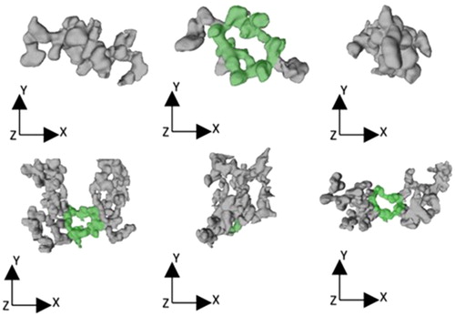
The videos and tomography also revealed the presence of ring structures. shows an example of the 3D solid model rendering of a soot aggregate, with a ring structure highlighted in green. Eight of the nine aggregates examined exhibited ring structures. The only aggregate that did not exhibit a ring structure was aggregate B, which is one of the smallest aggregates, while larger aggregates sometimes contained many ring structures. The rings present in soot aggregates are hidden at certain angles, and even if visible, cannot be distinguished (in 2D) from individual branches that overlap at a given viewing angle. For example, the 3D imaging revealed cases where large aggregates overlapped smaller (unattached) soot aggregates that did not appear distinct in an ordinary projection. Evidence of this can be found in the video of aggregate D in the SI. Given that the 3D model creation resulted in slightly smoothed (and perhaps thickened) structures, one might wonder if the rings are artificially closed by the modeling. However, the videos in the SI involve no such modeling yet exhibit the ring structures clearly.
Figure 3. Two 3D models of soot from three different angles. The observed ring structure is highlighted in green. Top: aggregate A; bottom: aggregate F.
Early studies simulating the aggregation process (Meakin Citation1987) suggested that when the particle-particle sticking probability is reduced substantially, denser aggregates result. However, 2D TEM images of fresh soot typically have the appearance of the simulated aggregates produced with perfect sticking. On the other hand, studies have shown that condensation of liquids or electric fields (Nyeki and Colbeck Citation1995) can cause substantial restructuring of aggregates. However, the flare-derived soot examined here appears to be free from any coatings, through the formation and dilution process, as indicated by an effective density typical of fresh soot (Kazemimanesh et al. Citation2019). The ring structures we observe are relatively subtler and would require only small rotations at the contact points between primary particles. Our imaging cannot determine whether such rotations occur during the soot formation, during dilution, or post sampling. However, it seems likely that restructuring could occur during formation, when the temperatures are high and the primary particles have not yet become “welded” by further surface growth.
4. Conclusions
This study showed that average primary particle size, projected area-equivalent diameter and aspect ratio can be reasonably estimated from 2D projections, at least for “typical” dry, fractal-like soot aggregates with a substantial number of primary particles. Different image processing algorithms, including manual measurements, produced slightly different measurements, but none were strongly dependent on orientation angle or projected aspect ratio. Primary particle size varied by less than 16% as projection angled changed, while projected area-equivalent diameter varied by only 6% across projection angles. Only seven aggregates were analyzed in detail, but the magnitude of the variations were very similar for all aggregates, so perhaps the sample size is representative, at least for aggregates with many primary particles. With the small sample size, we were not able to see any orientation biases from sampling, but even if there are preferential orientations, the impact on the measurements of primary particle size or projected area measurements should be very small, based on the discussion above. As automated image processing methods improve, it will be possible to strengthen the conclusions with larger sample sizes.
However, there are some inherently 3D features that are visible only using tomography. For example, the 3D imaging revealed cases where large aggregates overlapped smaller (unattached) aggregates that did not appear distinct in an ordinary projection. As another example, the tomographic videos and solid models highlighted the presence of ring structures in most of the aggregates—suggestive of aggregate restructuring after aggregation. As far as we know, this has not been observed experimentally before, but it would be a natural consequence of weak bonds between newly-connected primary particles. These ring structures are clearly visible in the videos produced directly from the tomographic imaging, without any of the expensive solid model creation needed to produce, for example, 3D printed soot models.
Supplemental data for this article can be accessed on the publisher's website.
Download Zip (185.1 MB)Acknowledgments
The authors thank Yiling Kang for her time processing images and manually contouring tomographic slices for the 3D model and Matt Johnson for the use of the Carleton University Vertical Flare Facility.
Notes
1 Nine aggregates were tomograpically imaged, but two of the aggregates had large portions which fell outside of the imaged area making it impossible to reliably measure aggregate area and aspect ratio.
Related Research Data
References
- Adachi, K., S. H. Chung, and P. R. Buseck. 2010. Shapes of soot aerosol particles and implications for their effects on climate. J. Geophys. Res. Atmos. 115.
- Adachi, K., S. H. Chung, H. Friedrich, and P. R. Buseck. 2007. Fractal parameters of individual soot particles determined using electron tomography: Implications for optical properties. J. Geophys. Res. Atmos. 112.
- Amin, H. M., and A. Bennett, W. L. Roberts. 2018. Determining fractal properties of soot aggregates and primary particle size distribution in counterflow flames up to 10 atm. Proc. Combust. Inst. 37.
- Batenburg, K. J., S. Bals, J. Sijbers, C. Kübel, P. Midgley, J. Hernandez, U. Kaiser, E. Encina, E. Coronado, and G. Van Tendeloo. 2009. 3D imaging of nanomaterials by discrete tomography. Ultramicroscopy 109 (6):730–740. doi: 10.1016/j.ultramic.2009.01.009.
- Brugière, E., F. Gensdarmes, F. Ouf, J. Yon, and A. Coppalle. 2014. Increase in thermophoretic velocity of carbon aggregates as a function of particle size. J. Aerosol Sci. 76:87–97. doi: 10.1016/j.jaerosci.2014.06.007.
- Brzostowski, M. A., and G. A. McMechan. 1992. 3D tomographic imaging of near-surface seismic velocity and attenuation. Geophysics 57 (3):396–403. doi: 10.1190/1.1443254.
- Chandler, M. F., Y. Teng, and U. O. Koylu. 2007. Diesel engine particulate emissions: A comparison of mobility and microscopy size measurements. Proc. Combust. Inst. 31 (2):2971–2979. doi: 10.1016/j.proci.2006.07.200.
- Chen, J., C. Li, Z. Ristovski, A. Milic, Y. Gu, M. S. Islam, S. Wang, J. Hao, H. Zhang, C. He, H. Guo, et al. 2017. A review of biomass burning: Emissions and impacts on air quality, health and climate in China. Sci. Total Environ. 579:1000–1034. doi: 10.1016/j.scitotenv.2016.11.025.
- Dastanpour, R., J. M. Boone, and S. N. Rogak. 2016. Automated primary particle sizing of nanoparticle aggregates by tem image analysis. Powder Technol. 295:218–224. doi: 10.1016/j.powtec.2016.03.027.
- Dastanpour, R., and S. N. Rogak. 2014. Observations of a correlation between primary particle and aggregate size for soot particles. Aerosol sci. Technol. 48 (10):1043–1049. doi: 10.1080/02786826.2014.955565.
- De Temmerman, P. J., E. Verleysen, J. Lammertyn, J. Mast. 2014. Semi-automatic size measurement of primary particles in aggregated nanomaterials by transmission electron microscopy. Powder Technol. 261:191–200.
- Eggersdorfer, M. L., D. Kadau, H. J. Herrmann, and S. E. Pratsinis. 2012. Aggregate morphology evolution by sintering: Number and diameter of primary particles. J. Aerosol Sci. 46:7–19. doi: 10.1016/j.jaerosci.2011.11.005.
- Farias, T. L., Ü. Ö. Köylü, and M. D G. Carvalho. 1996. Effects of polydispersity of aggregates and primary particles on radiative properties of simulated soot. J. Quant. Spectrosc. Radiat. Transfer 55 (3):357–371. doi: 10.1016/0022-4073(95)00166-2.
- Gray, R., G. Kanapilly, Y. Cheng, and R. Wolff. 1985. Image enhancement of aggregate aerosols by stereopsis. J. Aerosol sci. 16 (3):211–216. doi: 10.1016/0021-8502(85)90027-8.
- Heinson, Y. W., J. B. Maughan, W. R. Heinson, A. Chakrabarti, and C. M. Sorensen. 2016. Light scattering q‐space analysis of irregularly shaped particles. J. Geophys. Res. Atmos. 121:682–691. doi: 10.1002/2015JD024171.
- Jacob, M., T. Sanders, N. Bernier, A. Grenier, R. B. Pinheiro, F. Mazen, P. Bayle-Guillemaud, and Z. Saghi. 2018. Multivariate analysis and compressed sensing methods for spectroscopic electron tomography of semiconductor devices. Microsc. Microanal. 24 (S1):500–501. doi: 10.1017/S1431927618002994.
- Kazemimanesh, M., A. Moallemi, K. Thomson, G. Smallwood, P. Lobo, J. S. Olfert. 2019. A novel miniature inverted-flame burner for the generation of soot nanoparticles. Aerosol Sci Technol. 53 (2):184–195. doi: 10.1080/02786826.2018.1556774.
- Kook, S., and L. M. Pickett. 2012. Soot volume fraction and morphology of conventional, fischer-tropsch, coal-derived, and surrogate fuel at diesel conditions. SAE Int. J. Fuels Lubricants 5 (2):647–664. doi: 10.4271/2012-01-0678.
- Kremer, J. R., N. M. David, R. J. McIntosh. 1996. Computer visualization of three-dimensional image data using IMOD. J Struct Biol. 116.1:71–76.
- Lin, M., H. Lindsay, D. Weitz, R. Ball, R. Klein, and P. Meakin. 1989. Universality of fractal aggregates as probed by light scattering. Proc. R. Soc. Lond. A 423 (1864):71–87. doi: 10.1098/rspa.1989.0042.
- Mackowski, D. W., R. A. Altenkirch, M. P. Menguc. 1990. Internal absorption cross sections in a stratified sphere. Appl Opt. 29 (10):1551–1559.
- Meakin, P. 1987. Fractal aggregates. Adva Colloid Interface Sci. 28: 249–331.
- Mendes, M. 2009. A hybrid fast algorithm for first arrivals tomography. Geophys. Prospect. 57 (5):803–809. doi: 10.1111/j.1365-2478.2008.00755.x.
- Messaoudil, C., T. Boudier, C. O. S. Sorzano, and S. Marco. 2007. Tomoj: Tomography software for three-dimensional reconstruction in transmission electron microscopy. BMC Bioinformatics 8:288. doi: 10.1186/1471-2105-8-288.
- Moran, J., J. Cuevas, F. Liu, J. Yon, and A. Fuentes. 2018. Influence of primary particle polydispersity and overlapping on soot morphological parameters derived from numerical tem images. Powder Technol. 330:67–79. doi: 10.1016/j.powtec.2018.02.008.
- Nyeki, S., I. Colbeck. 1995. Fractal dimension analysis of single, in-situ, restructured carbonaceous aggregates. Aerosol Sci Technol. 23 (2):109–120.
- Okariz, A., T. Guraya, M. Iturrondobeitia, and J. Ibarretxe. 2017. A methodology for finding the optimal iteration number of the sirt algorithm for quantitative electron tomography. Ultramicroscopy 173:36–46. doi: 10.1016/j.ultramic.2016.10.013.
- Okyay, G., E. Héripré, T. Reiss, P. Haghi-Ashtiani, T. Auger, and F. Enguehard. 2016. Soot aggregate complex morphology: 3d geometry reconstruction by SEM tomography applied on soot issued from propane combustion. J. Aerosol Sci. 93:63–79. doi: 10.1016/j.jaerosci.2015.11.009.
- Orhan, O., E. Haffner-Staton, A. La Rocca, and M. Fay. 2016. Characterisation of flame-generated soot and soot-in-oil using electron tomography volume reconstructions and comparison with traditional 2d-tem measurements. Tribology Int. 104:272–284. doi: 10.1016/j.triboint.2016.09.015.
- Pandey, A., R. K. Chakrabarty, L. Liu, and M. I. Mishchenko. 2015. Empirical relationships between optical properties and equivalent diameters of fractal soot aggregates at 550 nm wavelength. Opt. Exp. 23 (24):A1354–A1362. doi: 10.1364/OE.23.0A1354.
- Rösner, H., S. Parida, D. Kramer, C. Volkert, and J. Weissmüller. 2007. Reconstructing a nanoporous metal in three dimensions: An electron tomography study of dealloyed gold leaf. Adv. Eng. Mater. 9 (7):535–541. doi: 10.1002/adem.200700063.
- Soewono, A., and S. N. Rogak. 2013. Morphology and optical properties of numerically simulated soot aggregates. Aerosol Sci. Technol. 47 (3):267–274. doi: 10.1080/02786826.2012.749972.
- Tian, K., F. Liu, M. Yang, K. A. Thomson, D. R. Snelling, and G. J. Smallwood. 2007. Numerical simulation aided relative optical density analysis of tem images for soot morphology determination. Proc. Combust. Inst. 31 (1):861–868. doi: 10.1016/j.proci.2006.07.064.
- Tian, K., K. A. Thomson, F. Liu, D. R. Snelling, G. J. Smallwood, and D. Wang. 2006. Determination of the morphology of soot aggregates using the relative optical density method for the analysis of tem images. Combust. Flame 144 (4):782–791. doi: 10.1016/j.combustflame.2005.06.017.
- Toth, P. J. D., M. Ek, and H. Wiinikka. 2019. Real-time, in situ, atomic scale observation of soot oxidation. Carbon Press.
- Van Poppel, L. H., H. Friedrich, J. Spinsby, S. H. Chung, J. H. Seinfeld, and P. R. Buseck. 2005. Electron tomography of nanoparticle clusters: Implications for atmospheric lifetimes and radiative forcing of soot. Geophys. Res. Lett. 32.
- Wentzel, M., H. Gorzawski, K.-H. Naumann, H. Saathoff, and S. Weinbruch. 2003. Transmission electron microscopical and aerosol dynamical characterization of soot aerosols. J. Aerosol Sci. 34 (10):1347–1370. doi: 10.1016/S0021-8502(03)00360-4.