
 ?Mathematical formulae have been encoded as MathML and are displayed in this HTML version using MathJax in order to improve their display. Uncheck the box to turn MathJax off. This feature requires Javascript. Click on a formula to zoom.
Abstract
We examined two emission abatement systems of some vulcanization ovens, serving a unit producing small rubber-based parts for automotive application. Each emission control unit treats the gases exhausted by three to five ovens. A heat exchanger cools down the fumes to a temperature suitable for the correct operation of a couple of two-stage electrostatic precipitators in series. We performed quantitative analysis of concentrations and size distributions in these rubber fumes using aerosol technology instrumentation, namely optical particle spectrometers and electrical mobility particle sizers. The size of sampled particles was mainly between 100 nm and 1000 nm. We evaluated the performance of the exhaust fume abatement units, with focus on the electrostatic precipitator. Concerning batch ovens, the quantitative trend of the emissions follows the thermal cycle of the post-curing process. Time interval since the last maintenance operation causes a gradual reduction in the removal efficiency. The measured data demonstrate the reliability and the adequacy of aerosol instrumentation for the characterization of the emissions from rubber vulcanization ovens. The pair of electrostatic precipitators was shown to be effective in removing most of the particles detected in the fumes stream. The measurement protocol developed in this study allows assessing the influence of the maintenance schedule on the performance of the emission control units. New technologies for treating organic vapors can be evaluated in a reliable and effective way.
Copyright © 2019 American Association for Aerosol Research
Introduction
Vulcanization irreversibly adds sulfur atoms to the elastomer molecules, improving their traction resistance and decreasing their vulnerability to oxidation (Callister Citation1999). Following the basic vulcanization process, molded elastomer parts frequently undergo "post-curing" treatments, such as exposure to UV radiation or further heating, which result in the release of chemicals and formation of liquid or solid particles. However, phenomena of coagulation in fumes exhausted by ovens working at 220 °C yield mostly suspended compact particles having a size in the range between a few nanometers up to ∼1 μm (Kim et al. Citation2013).
Establishing effective control systems and emission abatement strategies minimizing, as well, the effects on the manufacturing chain is a crucial issue in production processes with high health and environmental hazards, as in the case of rubber vulcanization industry, which is characterized by carcinogenic exhausts (International Agency for Research on Cancer Citation1982).
An opinion from the Scientific Committee on Occupational Exposure Limits (SCOEL, Santonen et al. Citation2016) defines rubber process fumes as “a variety of substances emitted from rubber compounds into a workplace atmosphere as a result of industrial processing, the composition of which depends on the formulation of the compounds concerned, the process technology in use, and the associated process parameters”. Thus, any discussion should consider all the possible physical forms in which they can be present in the workplace environment, that is, gases, vapors, and aerosols (Willoughby Citation2003; Forrest Citation2015).
Due to lack of recent (post-2010) data on the variable composition of rubber dusts and fumes, it is not possible to provide a recommended threshold value for exposure of rubber dusts or fumes correlated to cancer risk (Santonen et al. Citation2016). However, some standards impose binding limit values to the emission of fumes exhausted by processes of rubber industry (Health and Safety Executive Citation2005b).
Detecting all the constituents of rubber fumes in an effective way is not a trivial task because of their complex chemical composition and their diverse forms. Nudel’man (Citation2001) reported that aerosols from rubber goods production are formed both by mechanical stresses and local overheating at mixing stage and by condensation of emitted vapors of high boiling point substances during the vulcanization process. In both the cases, the aerosol particles contain in addition a mix of substances captured by the liquid droplets forming the aerosol itself.
This implies that different sampling and analysis methods may affect the measurement outcome. In fact, concerning visible fume, that is, the complex mix of aerosols derived from the condensation of hot vapors, the manner of monitoring is an integral part of the definition of rubber fume (Willoughby Citation2003). In particular, the development of a monitoring system for aerosols from rubber goods production should carefully take into account the influence of plasticizer aerosols on the sampling process itself (Forrest Citation2015).
Giese (Citation1999) followed the principles of applicable regulations, such as the German hazardous substances ordinance, to describe an efficient sampling and analysis method for monitoring air in the areas dedicated to vulcanization processes in rubber industry. Among the different substance categories present in field tests and analyzed, the aerosols were captured with glass-fiber filters and vapors by XAD-2 polymer adsorption tubes. A 94.0%–98.9% mass-based removal efficiency was measured.
Forrest mentions in his review (Forrest Citation2015) that Levin and Asplund captured aerosols and particulates released from a selection of rubber compounds using quartz wool filters. Forrest also points out that Blanden and Isherwood employed an ESP and glass fiber filters in five British sites to collect the particulate matter in the fumes from different rubber production processes.
3M’s Environmental Engineering and Pollution Control Laboratory (Dyneon Fluoroelastomers Citation2001) identified a two-stage dry or wet ESP as the most suitable abatement unit to reduce opacities and volatile matter in post-curing exhausts.
Kim et al. (Citation2013) carried out a mapping analysis based on five 40-min particle number concentration measurements, conducted by counting particles with a diameter ranging from 0.02 to 1.0 µm at intervals of 30 min, using a Condensation Particle Counter (CPC). As a result, they obtained a concentration map of the rubber manufacturing plant, with a peak near the workbench.
Objectives
The experimental procedures described here mainly aimed at evaluating the efficacy of the electrostatic precipitators (ESPs) installed in a factory for the removal of particles generated by rubber post-curing.
Since the composition of volatile substances exhausted by rubber post-cured in the specific facility under examination is not known, it is not possible to state a priori whether electrostatic precipitation is the best available technology for the abatement of pollutants contained in the exhausts. Therefore, the first objective of the research project was the verification of the usefulness of ESPs in our specific case study, especially in lack of information from literature about the suitability of such mitigation measures in our specific case study.
Hence, a preliminary analysis was necessary to verify the presence of sufficient concentrations of particles and then correlate their size distribution to the performance of ESPs.
These elements led to the evaluation of the use of instruments like particle sizers for the quantification of the aerosol emissions from rubber post-curing ovens: the possibility of performing the sampling and the immediate analysis of data using the same instrument makes this solution very attractive. Some of the available aerosol instrumentation not only allows the analysis of the emissions with portable devices measuring with a time resolution on the order of seconds or minutes but also providing estimates of the quantity of contaminants exhausted by the pieces undergoing vulcanization, even without knowing the chemical composition of these materials. That is particularly important when the chemical composition of vulcanized materials is patented and therefore undisclosed. Moreover, when one aims at evaluating the performance of devices that remove particulate contaminants, it is necessary to use the aerosol instrumentation to combine and align the resulting efficiency with the data of concentrations. Indeed, sampling a chemical substance without knowing whether it is gaseous or liquid/solid does not allow evaluating the suitability of the technologies and devices used for controlling the emissions. We did not find any information about the use of aerosol instrumentation in the scientific literature for the purification of the exhaust fumes produced by this specific manufacturing process. In fact, the most common methods for the study of particles emitted by rubber curing are differential gravimetric analysis (Dyneon Fluoroelastomers Citation2001; Health and Safety Executive Citation2005a; de Vocht et al. Citation2006) and Fourier transform infrared spectroscopy (Giese Citation1999). Hence, the aim of this article is to provide scientific evidence about the possibility of using this kind of devices for the real-time detection of rubber fume emissions.
The article provides a sound in situ assessment of the performance of ESPs used for purifying vulcanization fumes: the results of the measurements, critically analyzed in this work, justify the adoption of ESPs as purifying devices for rubber fumes.
A further objective of the research work is to establish a correlation between the maintenance time interval and the removal efficiency of ESPs for typical rubber fumes. The performance of the abatement system progressively decreases, because of the build-up of particles on the collection plates, especially particles with high electric resistivity (Parker Citation2003).
Facility description
We studied two emission treatment units downstream of post-curing ovens, serving a plant producing small parts containing rubber for the automotive sector. We focused on the emissions exhausted by two different types of ovens, chosen by the technical staff of the factory. Five in-line ovens are connected to an emission control unit, and three batch ovens are connected to another unit. The temperature of the studied post-curing ovens has a maximum of 220 ± 3 °C.
The five in-line ovens (denoted as C1–C5) work continuously, that is, they steadily treat rubber parts that are loaded according to a uniform schedule with a quick opening and closing of the inlet shutter.
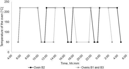
On the other hand, the three batch ovens (indicated as B1–B3) follow an extended cyclic schedule. Each of the four daily cycles of oven B2 lasts about 6 h, consisting of a 25-min temperature ramp-up from 50 to 220 °C, followed by a 4-h phase at a constant 220 °C temperature, a final 50-min cool-down to 50 °C and a 45-min pause at low temperature. The ovens B1 and B3 run three cycles per day lasting 8 h each: the difference from the schedule of oven B2 consists in the additional 2 h for the final low-T pause interval, as shown in .
Figure 1. Cyclic schedule of the batch post-curing ovens.
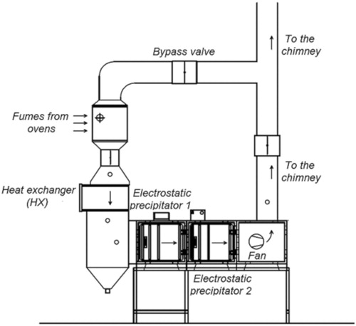
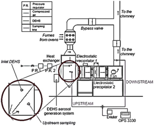
One of the two pollution control units () treats the fumes exhausted by the three batch ovens; the other one served the five in-line ovens. Each emission control unit removes particles from an exhausted flow rate of less than 1000 m3 h−1 at a duct velocity of about 3.8 m s−1. In each treatment unit, a heat exchanger cools the fumes down to a temperature value suitable for the correct operation of the downstream two-stage ESPs (around 30 °C). Each stage of the precipitators has a corona-discharge ionization section and an array of parallel collection plates.
Figure 2. Emission abatement system of the facility studied.
Protocol for efficiency measurements
We performed several measurements on particles in the exhaust fumes using the following instruments:
TSI “Optical Particle Sizer (OPS) model 3330” (TSI Citation2011); the software used for the collection of data is the TSI Aerosol Instrument Manager (AIM).
TSI “Nanoscan SMPS Nanoparticle Sizer model 3910” (TSI Citation2013); the instrument can be used in single mode by setting one particle size or scan mode (measuring particle concentration in 13 size channels between 10 and 420 nm). The data are provided by the TSI Nanoscan Manager (NM) software.
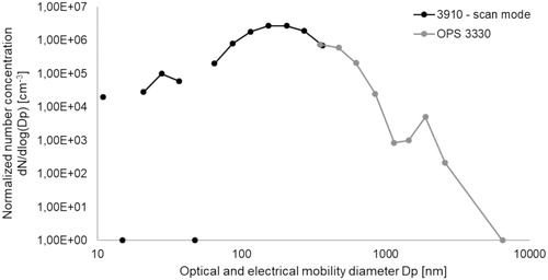
To know the size distribution of particles between 10 and 10,000 nm, we combined the data provided by those two instruments. We measured particle number concentrations with TSI 3910 operating in single mode between 10 and 400 nm. We set TSI 3910 in single mode, because size distributions in the exhaust air were fluctuating, resulting in “holes” at the lowest range of the spectrum (). It should also be noted that although the TSI 3910 is specified to have a lower size limit at 10 nm, it may not be very accurate in its lower size range (Fonseca et al. Citation2016). Furthermore, it cannot be excluded that particles are formed due to nucleation in the rubber curing process. These would be even smaller and not detectable with the TSI 3910.
Figure 3. Typical normalized size distribution of the aerosol downstream of post-curing ovens.
We set the following particle size bounds for measurements with TSI 3330: 300, 400, 550, 700, 1000, 1300, 1600, 2200, 3000, and 10,000 nm. In every test session, the dilution factor is set varying the bypass flow rate of sample fumes to the external diluter to avoid overloading the instrument measuring the particle concentrations upstream and downstream of the ESP.
Since the width of the size channels in the single size mode of the TSI 3910 is unknown, concentration data could not be normalized to dlog(dp). However, this is not essential here, as the main goal of using the single size mode was to monitor the variation in concentrations of particles of a known mobility size (TSI Citation2013).
The match when the scan mode was used by the TSI 3910 () shows good agreement between the two instruments at 350 nm.
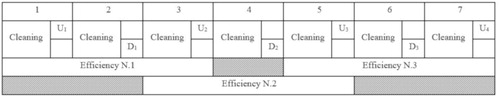
We also performed validation tests and measurements of the removal efficiency approximately following ISO 16890:2016 (International Organization of Standardization Citation2016). Despite the differences among standards concerning contaminant conditions, scale, and sampling (Tronville and Rivers Citation2005), we followed this International Standard for testing and rating air filters due to its minor variations for the equipment and procedure of particle capture efficiency measurement (Tronville and Rivers Citation2016). In general, we measured particle concentrations upstream and downstream of the ESP following the schedule in . Each of the seven sampling slots lasted 3 min (one for cleaning, two for the measurement of particle concentrations).
A sensitivity analysis using TSI OPS 3330 to measure particle concentrations optimized the schedule of . We found it desirable to perform a higher number of short-duration samples, getting a more accurate set of efficiency outcomes, rather than long-duration samples. The decision of sample duration is a tradeoff aimed to reduce the time for measurements and enhance the goodness of results.
We obtained three different efficiency values Ei,j for the jth size channel in the ith sampling period, then averaged to get a single representative efficiency result:
(1)
(1)
Here, U and D are the upstream and downstream particle concentrations, respectively.
Test rig and validation
In situ validation measurement in controlled conditions
At first, we investigated the reliability of the results of measurements on the emission abatement units under examination. Therefore, we carried out a validation of the test rig by comparing the outcomes obtained in situ with those of a laboratory apparatus, operating according to international standards and in controlled conditions ().
Figure 4. Schedule of the samplings for one single measurement of efficiency.
The larger circle in shows the location of the inlet for di-ethyl-hexyl-sebacate (DEHS) aerosol into the test rig, and the location of the sampling probe upstream of the ESP. A diagonal baffle plate cut short at its lower end is installed across the tube between these two locations: the small gap generates a turbulent flow at this point with high velocity which mixes the aerosol in the exhaust stream, hence ensuring a more constant concentration at the sampling point upstream of the ESP.
Three different efficiency values Ei,j were obtained for the jth size channel in the ith sampling period, and then averaged to get a single efficiency result. We repeated the sampling procedure described in four times, progressively modifying the value of concentration k, obtained regulating the pressure of the inlet flow of compressed air and consequently changing the dilution factor to avoid overloading the particle sizer with excessively high inlet concentrations. We replicated this measurement for four days (index d) in the same conditions and following the same method, to appreciate variations of fractional removal efficiency:
(2)
(2)
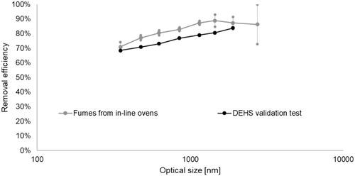
compares the performance against DEHS aerosol of precipitators serving the batch ovens with the fractional efficiency curve of the ESPs downstream of the in-line ovens during usual post-curing operation (data come from preliminary tests assessing the effective operation of the ESP systems). The two curves of fractional removal efficiency versus optical dimension of particles agree fairly well, although the particle concentrations vary in the two measurements due to different operating modes and sampling conditions of the two systems.
Figure 5. Portable test rig for the validation tests performed using DEHS.
Validation with measurements in laboratory
The second step of the study aimed at evaluating whether the portable test apparatus used in situ provided data consistent with those measured by standard ISO 16890:2016.
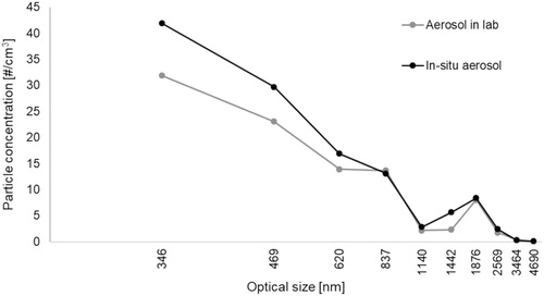
As a first step, the size distribution of the DEHS aerosol produced with the portable test setup () used for in situ measurements was compared with the one generated by a Laskin nozzle for standardized tests in the research laboratory on filtering media of the Department of Energy (DENERG) at Politecnico di Torino. As shown by the log-linear curves in , the two size distributions agree quite well.
Figure 6. Validation of measurement with OPS 3330 through the comparison of fractional removal efficiency (data not shown up to 10 mm due to few particles).
The layouts of the two setups studied present several differences that may lead to mismatching efficiency outcome:
in the laboratory, an all-in-one program developed in-house is used instead of AIM and NM software by TSI: it allows at the same time to run the particle sizer, modify the speed of fans of the circuit to set the correct flow rate, and manage the sampling procedure;
in the laboratory, a system of three different one-way valves automatically manages the opening and closing of upstream/downstream sampling line or cleaning HEPA unit following the schedule shown in . On the contrary, the management of the sampling system for the in situ measurements relies on a manual three-way valve.
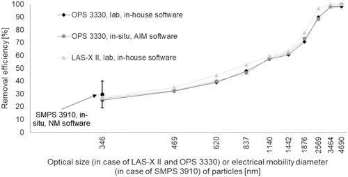
We performed some further tests to verify the coherence between the portable test setup used in situ and the laboratory test apparatus. In the same test sessions, we also checked the consistency among different particle sampling instruments by measuring the removal efficiency of a filter with well-known performance in four different ways:
TSI OPS 3330 with the lab test rig and in-house software;
TSI OPS 3330 with the portable rig to be used in situ and AIM software;
TSI SMPS 3910 with the portable rig to be used in situ and NM software;
PMS LAS-X II with the lab test rig and in-house software.
We checked whether the efficiency data obtained with different devices are coherent. We set the SMPS 3910 spectrometer in single mode to the geometric mean size of the first sampling channel of the OPS 3330, that is, at 346 nm. The uncertainty associated to particle concentration measurement performed in single mode with TSI 3910 does not affect appreciably the measured device efficiency because the efficiency is determined by the ratio of the upstream and downstream particle concentration. The results of a past inter-laboratory validation analysis shows good agreement of the efficiency data measured in single mode using the TSI 3910 and the data provided by more sophisticated instrumentation (Sachinidou et al. Citation2017).
shows the agreement of the results of the four different test setups specified before, confirming the goodness of the efficiency curve of the OPS 3330 and the coherence of the efficiencies obtained with SMPS 3910 and OPS 3330 in the overlapping sampling channel.
Figure 7. Size distributions of aerosols produced with different test setups.
Measurements with ovens in service
Before proceeding with the analysis of efficiency measurements, we report some preliminary outcomes regarding the response of particle concentrations during the normal operation of batch ovens.
Influence of the operation of batch ovens on particle concentration
Unlike in-line ovens, batch ovens follow a cyclic, discontinuous schedule that we suppose affects the evolution in time of the particle concentration. In fact, this variation of the oven temperature determines a progressive evaporation of substances, starting from those characterized by a low boiling point.
We examined the variation of particle concentration across the cooler and the ESP in the emissions control unit serving the batch ovens. We employed both SMPS 3910 and OPS 3330, with sampling durations long enough to show the change in particle concentrations.
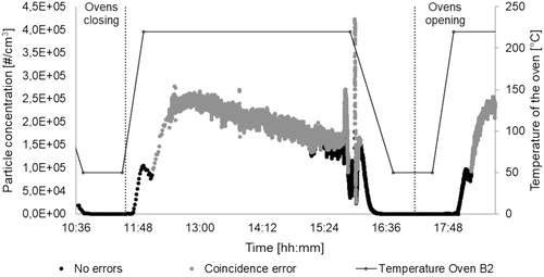
The results of both the tests (shown in and ) confirmed our expectations: apart from the changes due to the sampling uncertainty, the macroscopic evolution in time of particle concentrations matches fairly well the trend of the temperature inside the ovens. In fact, we can notice a quick increment during the startup, a plateau when the temperature stays constant, and a reduction in the cool-down phase. In some cases, the particle concentration exceeded the maximum value accepted by the instruments (especially when using OPS 3330, despite adopting the highest dilution factor possible).
Figure 8. Comparison of fractional removal efficiency measured with different instrumentation and configurations.
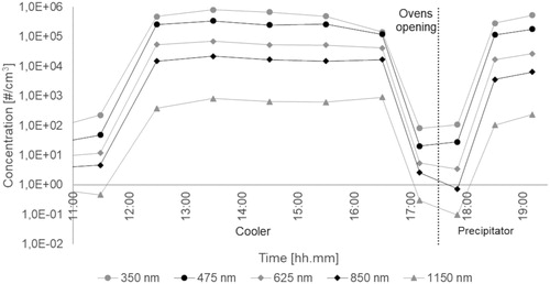
shows the evolution in time of the particle number concentrations sampled with OPS 3330 and averaged on an hourly basis: it clearly highlights the correlation between the oven temperature (compare ) and the particle concentrations in the exhaust fumes. We performed the measurements at the downstream sections of both the cooler and the ESP. One can also notice the progressive decrease in the measured particle concentrations as the optical diameter of particles increases.
Figure 9. Particle concentration versus time across the ESP downstream of batch ovens measured with SMPS 3910 – 100 nm – No dilution.
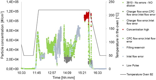
Figure 10. Particle concentration (downstream section of the cooler serving the batch ovens) versus time measured with OPS 3330 – 350 nm – Dilution 1:15 before 11:16, 1:100 afterwards.
Efficiency measurement of ESPs serving in-line ovens
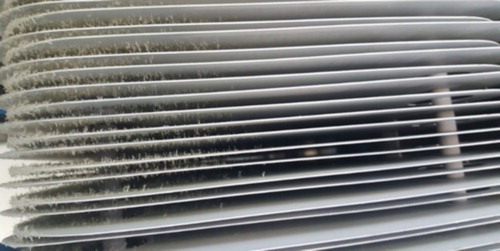
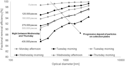
We carried out a set of tests with OPS 3330 focused on the evolution in time of the removal efficiency of the ESPs placed in the emission control unit serving the in-line ovens. The analysis proved that the time elapsed from the last maintenance operation on the ESP is a key parameter influencing its performance. In fact, the degree of obstruction across the ESP due to the deposit of particles on the arrays of collection plates clearly depends on the maintenance schedule. This phenomenon is evident at the entrance of the capture ) and inevitably alters the uniformity of the electric field, with clear effects on the removal efficiency against particles.
Figure 11. Hourly average particle concentrations downstream of batch ovens versus time. Measured with OPS 3330 – Dilution 1:370 for cooler; for precipitator, 1:200 between 17:39 and 18:37, 1:300 afterwards.
To verify the progressive reduction of removal efficiency with the increasing clogging of particles on the collection plates, we carried out six efficiency tests throughout four days between two subsequent maintenance operations planned on Mondays and Thursdays around noon. The results in all refer to the ESP in the abatement system serving in-line ovens. Our expectation is confirmed by the evident proportionality linking the degradation of fractional removal efficiency in consecutive tests with the cumulative amount of post-cured rubber pieces, representing the activity of the ovens (numbers provided in ).
Figure 12. Top view of collection plates with progressive build-up of particles (fumes enter from left side).
Discussion
All the experimental tests carried out on the emission abatement system serving the batch ovens highlighted the strict influence of the temperature of the fumes on particle concentration. We also noted that the size of sampled particles is between 100 nm and 1000 nm, with the mode around 150–200 nm.
Concerning batch ovens, the quantitative trend of the emissions follows the thermal cycle of the post-curing process. In particular, the peak occurs around 20–30 min after the startup: this is the approximate time for rubber parts to reach the maximum temperature after the evaporation of low-boiling substances. The peak first relates to fine particles that rapidly evaporate in the ovens; afterwards, complex compounds are post-cured giving rise to larger particles detected by the instruments.
ESPs can ensure a good removal of such pollutants, at least in the control unit serving the in-line ovens, if maintenance follows a suitable schedule and is effectively carried out. In fact, the time interval since the last maintenance operation is an insidious variable of the system since it causes a gradual reduction of the removal efficiency, particularly against low-diameter particles.
In this regard, we observed the reduction in removal efficiency in time, that is, as a function of the cumulative number of processed pieces or the time passed since the last maintenance intervention. highlights that this performance loss against particles with optical diameter equal to 350 nm is linear. In the sampling period of 72 h, the efficiency continuously dropped from around 99% to 85%, which means a 14-fold increase in the emission. The direct proportionality between the efficiency of the ESP and the mass of treated rubber pieces is valid also in the case of batch ovens: the decrease in the efficiency is much slower, probably because the ESP serving the batch ovens has been manufactured later than the one used for the in-line ovens.
Figure 13. Evolution in time of the fractional removal efficiency of ESPs serving in-line ovens; the number of pieces refers to the number of rubber pieces treated inside the oven since its last maintenance.
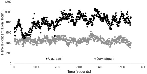
The influence of maintenance on the removal performance is evident in , where the concentration of 350-nm particles measured with Nanoscan 3910 in single mode upstream of the ESP is almost double with respect to the downstream value: this implies a removal efficiency of about 50%. This value is very low with respect to the typical performance indicators of ESPs and may be correlated to an ineffective schedule for the maintenance of the batch control unit.
Figure 14. Dependence of the removal efficiency toward 350 nm particles on the amount of post-cured rubber parts.
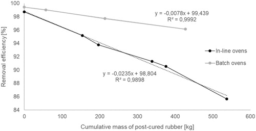
Figure 15. Particle concentration versus time across the ESP downstream of batch ovens measured with SMPS 3910 – 350 nm – No dilution.
Conclusions
A preliminary sensitivity analysis regarding the measuring protocol of emissions from post-curing ovens points out that it is desirable to perform a high number of short-duration samples, getting a more accurate set of efficiency outcomes, rather than a single long-lasting sample unavoidably associated to uncertainty due to unpredictable trends of the particle concentrations.
We carried out several validation steps. The DEHS aerosol produced by the portable test setup for in situ validation tests is characterized by a size distribution that agrees fairly well with that of the aerosol employed in laboratory tests. The portable test apparatus also gave coherent efficiency data as confirmed by the use of different aerosol measuring instruments. Thus, DEHS aerosol seems to mimic well the behavior of the particles contained in rubber fumes.
The results of the experimental tests carried out in this work confirmed our decision of using aerosol instrumentation for monitoring and measuring the fractional removal efficiency of the system intended to remove the pollutants in rubber post-curing fumes. Precipitators show a remarkable removal efficiency, usually over 90% for all particle sizes if maintenance follows an adequate schedule. In fact, time passed since the last maintenance operation causes a progressive degradation of the removal efficiency, particularly against low-diameter particles: a suitable maintenance strategy should limit this detrimental phenomenon, while limiting costs as much as possible. We can assume that continuous monitoring systems with low-cost sensors would be beneficial to optimize maintenance intervals. However, it is firstly necessary to check the correlations with more expensive and accurate instruments, to be sure that low-cost devices would be able to sample exhausted particles without being overloaded. Indeed, the main limitation is that, at the moment, there is no low-cost diluter on the market.
In the plant under examination, the centralized ventilation strategy employed mixing of the contaminants with the air of the workplace. Instead, a control and abatement system, installed close to the source of emissions would be preferable. In fact, the removal efficiency of ESPs operating against highly concentrated pollutants in lower, undiluted flows of fumes would probably increase. This enhancement requires the precipitator maintenance schedule to be changed to avoid the clogging of the collection plates.
Acknowledgment
The authors thank Richard Rivers (EQS Inc., Louisville, KY) for his help in reviewing and improving the article.
References
- Callister, W. D. 1999. Scienza e ingegneria dei materiali una introduzione. Naples, Italy: EdiSES.
- Dyneon Fluoroelastomers 2001. “Eliminating volatiles from oven exhaust when post curing fluoroelastomer parts. Oakdale, MN: Dyneon LLC. http://multimedia.3m.com/mws/media/103144O/eliminating-volatiles-when-post-curing-fkm-parts.pdf
- Fonseca, A. S., M. Viana, N. Pérez, A. Alastuey, X. Querol, H. Kaminski, A. M. Todea, C. Monz, and C. Asbach. 2016. Intercomparison of a portable and two stationary mobility particle sizers for nanoscale aerosol measurements. Aerosol. Sci. Technol. 50 (7):653–668. doi: 10.1080/02786826.2016.1174329.
- Forrest, M. 2015. The composition and nature of vulcanisation fumes in the rubber industry—a technical review. Progress Rubber, Plastics Recycling Technol. 31 (4):219–264. doi: 10.1177/147776061503100401.
- Giese, U. 1999. Sampling and analysis of emissions in the rubber industry. Manchester: DIK-Publikation. https://www.dikautschuk.de/fileadmin/files/leseproben/p_0120.pdf
- Health and Safety Executive 2005a. “Determination of rubber process dust and rubber fume (measured as cyclohexane-soluble material) in air.” UK. Published by the Health and Safety Executive (MDHS47/3 - 03/15). http://www.hse.gov.uk/pubns/mdhs/pdfs/mdhs47-3.pdf
- Health and Safety Executive 2005b. “EH40/2005 workplace exposure limits.” Norwich, UK: TSO (The Stationery Office). http://www.hse.gov.uk/pubns/priced/eh40.pdf.
- International Agency for Research on Cancer 1982. Evaluation of the carcinogenic risk of chemicals to humans.” Lyon, France: The Rubber Industry.
- International Organization of Standardization 2016. ISO 16890—Air filters for general Ventilation—Part 2: Measurement of fractional efficiency and air flow resistance. Geneva, Switzerland. International Organization of Standardization. https://www.iso.org/standard/57865.html
- Kim, B., J. Seong Lee, B. Soon Choi, S. Young Park, J. Ha Yoon, and H. Kim. 2013. Ultrafine particle characteristics in a rubber manufacturing factory. Ann. Occupat. Hygiene 57 (6):728–739. doi: 10.1093/annhyg/mes102.
- Nudel’man, Z. N. 2001. Ecological and hygiene hazards in the production of mechanical rubber goods. A new evaluation. Int. Polym. Sci. Technol. 28 (4):38–42.
- Parker, K., MPG Books Ltd. 2003. Electrical operation of electrostatic precipitators. 1st ed. Bodmin, Cornwall: IET Power & Energy series. https://doi.org/10.1049/PBPO041E.
- Sachinidou, P., Y. K. Bahk, M. Tang, N. Zhang, S. S. C. Chen, D. Y. H. Pui, B. A. Lima, G. Bosco, P. Tronville, T. Mosimann, M. Eriksson, and J. Wang. 2017. Inter-Laboratory validation of the method to determine the filtration efficiency for airborne particles in the 3–500 Nm range and results sensitivity analysis. Aerosol Air Quality Res. 17 (11):2669–2680. doi: 10.4209/aaqr.2017.03.0104.
- Santonen, T., A. Moretto, D. Papameletiou, and C. L. Klein. 2016. Rubber fumes and dusts. SCOEL/OPIN/2016-402. Brussels. Luxembourg: Publications Office of the European Union. doi: 10.2767/109431.
- Tronville, P., and R. D. Rivers. 2005. International standards: filters for buildings and gas turbines. Filtration Separation 42 (September):39–43. https://doi.org/10.1016/S0015-1882(05)70623-6. doi: 10.1016/S0015-1882(05)70623-6.
- Tronville, P., and R. D. Rivers. 2016. Air filter performance: new method for testing. ASHRAE J. 58 (May): 14–25.
- TSI 2011. Optical particle sizer spectrometer model 3330—operation and service manual. Shoreview, MN: TSI 5.1–5.4.
- TSI 2013. Nanoscan SMPS nanoparticle sizer model 3910—operation and service manual. Shoreview, MN: TSI.
- Vocht, F. D., D. Huizer, M. Prause, K. Jakobsson, B. Peplonska, K. Straif, and H. Kromhout. 2006. Field comparison of inhalable aerosol samplers applied in the European rubber manufacturing industry. Int. Archives Occupat. Environ. Health 79 (8):621–629. doi: 10.1007/s00420-006-0087-6.
- Willoughby, B. G. 2003. Air monitoring in the rubber and plastics industries. 1st ed. Shropshire, UK: Rapra Technology Limited.