
Abstract
Particle charging via the mixing of aerosols with unipolar ions typically results in multiple charges on particles. Particle classification and sizing, based on the electrical mobility, ideally requires all the particles being singly charged to the performance enhancement. In this study, we explored the feasibility of maximizing the singly charged fraction of particles via the control of the Nit product in a unipolar charger. The feasibility was first investigated by modeling unipolar diffusion charging. It was found that the singly charged fraction of monodisperse particles could be maximized by the control of the Nit product. A corona-based unipolar charger was also constructed to study the maximization of the singly charged fraction of monodisperse particles. It was found that a wider range of ion concentration in the charging zone could be obtained by the variation of ion-driving voltage compared to that by changing the corona-discharge current. The maximum singly charged fraction of monodisperse particles in various sizes was characterized when the charger was operated at the flow rates of 1.5 and 3.0 lpm. It was evidenced that the current charger could be conditioned to achieve a higher singly charged fraction of particles than that by bipolar chargers in the particle size range of 20–200 nm, particularly in the ultrafine particle size range. The control of Nit product in the charging zone of a unipolar charger offers a simple and effective means to enhance the singly charged fraction of particles in a given size range.
Copyright © 2019 American Association for Aerosol Research
EDITOR:
1. Introduction
Charging sub-micrometer particles via the mixing of particles with unipolar/bipolar ions are widely applied for controlling or measuring particles via the electrostatic means. Compared to bipolar chargers, unipolar chargers typically achieve higher charging efficiency (Chen and Pui Citation1999; Intra and Tippayawong Citation2011). A unipolar charger, combined with a differential mobility analyzer (DMA), could be used to select particles in a narrow electrical mobility size range. A DMA classifies electrically charged particles based on electrical mobility by tuning the strength of the electric field in the DMA particle classification channel (Knutson and Whitby Citation1975). When combined with a particle concentration detector, the integrated system could be used to measure electrical mobility size distribution of sub-micrometer particles (Chen, Yeh, and Johnson Citation1996; Hewitt Citation1957; Hsiao et al. Citation2016). However, the mixing of unipolar ions with particles in a particle charger typically results in particles carrying zero, single, double, triple, and more charges, i.e., in an integer-numbered charge distribution. Large particles carrying multiple charges could have the same electrical mobility as small ones carrying a single charge, resulting in multiple physical sizes in DMA-classified particles. It is desired, but challenging, to have all the sampled particles singly charged for the particle classification and measurement. The singly charged fraction of monodisperse particles is defined as the percentage of the concentration of particles carrying a single positive or negative charge to that of all the particles exiting a charger. The maximization of the fraction of singly charged particles exiting a unipolar charger is expected to improve the accuracy of DMAs for classifying or sizing particles. Although other techniques have been proposed for particle classification, additional equipment is required in these methods (Ock et al. Citation2018; Tavakoli, Symonds, and Olfert Citation2014). Thus, it is meaningful to tune operational parameters of a unipolar charger for maximizing the singly charged fraction of particles.
The charging efficiency, average charges, and charge distribution of particles are typically applied to characterize the performance of unipolar chargers (Marquard, Meyer, and Kasper Citation2006a, Citation2006b). The former two have been applied in commercial particle sizers, for example, ELPI+ (Electrical Low-Pressure Impactor, Dekati Ltd., Finland), NAIS (Neutral Cluster and Air Ion Spectrometer, Airel Ltd., Estonia), and FMPS (Fast Mobility Particle Sizer, TSI Corp., Shoreview, MN, USA). However, limited studies were focused on the charge distribution of particles exiting unipolar chargers (Alguacil and Alonso Citation2006; Biskos, Reavell, and Collings Citation2005; Li and Chen Citation2011; Qi, Chen, and Greenberg Citation2008; Qi, Chen, and Pui Citation2007; Vivas, Hontañón, and Schmidt-Ott Citation2008). The enhancement of the fraction of singly charged particles has been studied in bipolar charging (Gupta and McMurry Citation1989; Han et al. Citation2003). For the unipolar charging, the first study on the singly charged fraction enhancement was reported by Vivas et al. (Citation2008). Vivas et al. (Citation2008) applied pulsed ion-driving voltage to vary the ion concentration and charging time in the charging zone of a corona charger, achieving significant improvement on the singly charged fraction of monodisperse particles. Alternatively, the ion concentration in the charging zone of a unipolar charger using corona discharge as ion sources could be varied via the change of DC ion-driving voltage and corona-discharge current (Chen et al. Citation2018; Qi, Chen, and Greenberg Citation2008). The above ion-control approaches have, however, not been explored to maximize the singly charged fraction of monodisperse particles in a unipolar charger.
The objective of this study is to investigate the particle charge conditioning in a unipolar charger with the focus on the maximization of the fraction of singly charged monodisperse particles. In this study, we first explored the feasibility of maximizing the fraction of singly charged particles in a unipolar charger via the simple modeling of unipolar diffusion charging under various Nit products (where Ni is the ion concentration and t is the particle residence time in the charging zone of a charger). A unipolar charger, capable of varying the DC ion-driving voltage and corona-discharge current, was then constructed. The operational parameters were tuned for achieving the maximum singly charged fraction of particles at different sizes and two different flow rates. The singly charged fraction of monodisperse particles was also characterized in this work.
2. Comparison between calculated and measured singly charged fractions
The birth-and-death charging model (Boisdron and Brock Citation1970) was applied to investigate the maximum singly charged fraction of monodisperse particles, which is ideally achievable in a unipolar charger. Under the assumption of no particle loss, Nit product, the product of ion concentration (Ni), and particle residence time (t) in the charging zone of a charger, is the key parameter in the charging model to determine the charging status of monodisperse particles. The Fuchs limiting-sphere theory (Fuchs Citation1963; Hoppel and Frick Citation1986) was used to estimate the ion-particle combination coefficient required in the model. The electrical mobility and mass of positive ions applied in our calculation were 1.15 × 10⁻⁴ m2 V−1 s−1 and 140 relative atomic mass, respectively (Hussin et al. Citation1983). The reason to choose positive ions for charging is that most corona-based unipolar chargers operate in the positive-ion mode for the aerosol measurement. Further calculation using different ion properties showed little effect on the trend or maximum singly charged fraction of monodisperse particles in unipolar diffusion charging, but would influence the optimal Nit product. Notice that the optimal Nit product discussed herein should be considered as an equivalent parameter. The exact value of the optimal Nit product is influence by many non-ideal parameters, such as the variation of ion properties, distribution of particle residence time, and distribution of ion concentration, which were not taken into consideration in this model.
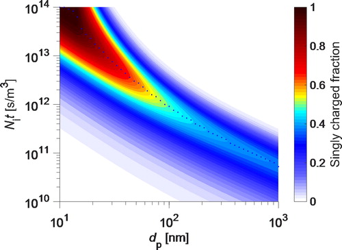
The singly charged fraction, f(+1), of monodisperse particles as a function of Nit product and particle size, is plotted in . For a given particle size, the singly charged fraction of particles increases with the increase of Nit product and reaches the maximum at a certain Nit product (i.e., the optimal Nit product), which is plotted as dots in . As Nit product further increases, the fraction of particles with single charge decreases and the fraction of particles with multiple charges increases. Moreover, both the optimal Nit product and maximum singly charged fraction, fm(+1), of particles decrease as the particle size increases. This phenomenon is also shown in in the online supplementary information (SI). It is expected that the fm(+1) of monodisperse particles is achieved when the average charge on particles is close to one (evidenced in ). The average charge on monodisperse particles can thus be a good indicator for reaching the maximum singly charged particle fraction.
Figure 1. The singly charged fraction of particles as a function of particle size and Nit product (the product of ion concentration and particle residence time in the charging zone of a charger) in a unipolar charger. Dots in the figure represent the maximum singly charged fraction of particles of a certain size at the optimal Nit product.
shows the comparison between the calculated maximum singly charged fraction of monodisperse particles and measured singly charged fractions of particles reported in previous studies. The singly positively charged fraction of monodisperse particles in bipolar charging, which was calculated by Fuchs charging model and approximated by an empirical expression (Wiedensohler Citation1988), is also included in for reference. The majority of measured singly charged fractions of monodisperse particles are less than the calculated fm(+1). One reason is that all unipolar chargers, except that in Vivas et al. (Citation2008), were operated at a fixed Nit product, which is not optimal for all particle sizes. The other reason is that all the measured singly charged fractions of monodisperse particles were derived from the measurement of extrinsic charge distribution of particles exiting a charger. It is impossible to separately measure the loss of particles carrying different number of charges to obtain the true charging status inside the charger via the current measurement technique. The latter might also be the reason why some data reported by Vivas et al. (Citation2008) exceed the calculated fm(+1).
Figure 2. The comparison of the maximum singly charged fraction of particles obtained in the modeling, singly positively-charged fractions in bipolar charging (Wiedensohler Citation1988), and singly charged fraction of monodisperse particles in unipolar charging reported in previous studies.
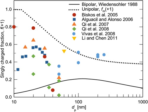
Due to the concern of multiple charges on particles, previous unipolar charging studies were mainly focused on ultrafine particles (), which are defined as particles in sizes less than 100 nm. Particles in the ultrafine size range could only acquire a limited number of charges in unipolar diffusion charging due to the Coulomb repulsion between free ions and attached charges.
3. Design of a unipolar particle charger and experimental setup
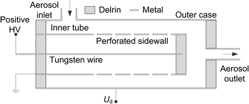
A unipolar charger capable of varying the DC ion-driving voltage and corona-discharge current was constructed to experimentally investigate the maximum singly charged fraction of monodisperse particles achievable in a unipolar charger. The schematic of the unipolar charger is shown in . This charger is similar in the configuration to that used in electrical aerosol analyzers (EAA, Pui, Fruin, and McMurry Citation1988). The dimensions of the current charger are 1.75′′ (4.4 cm) in diameter and 3.0′′ (7.6 cm) in length. The charger was constructed by coaxially aligning the inner tube cage and outer cylinder case. The inner tube, with a perforated sidewall, was sealed at the end, and it was served as a chamber where ions would be generated via the DC-corona discharge. A tungsten wire in the diameter of 50 μm (Alfa Aesar, Thermo Fisher Scientific Chemicals Inc., USA) was placed along the cage axis. A positive high voltage was applied to the wire and the tube cage was electrically grounded. Ions were produced when the electric field around the wire was above the electrical breakdown threshold of the carrier gas, i.e., air. The corona-discharge current could be tuned by varying the applied high voltage. Generated ions would migrate through the perforated wall of the inner tube cage and enter the particle charging zone, which is the annular space between the perforated wall and the outer case. Particles flowed in the charger from the inlet tube vertically installed at the outer case, and moved to the charging zone, in which they mixed with unipolar ions. Particles exited from the outlet tube at the downstream end of the outer case. A DC ion-driving voltage (Ud) was applied to the outer case. The ion concentration in the charging zone of the charger could be varied either by changing the corona current or ion-driving voltage.
Figure 3. Schematic diagram of the unipolar particle charger studied in this work.
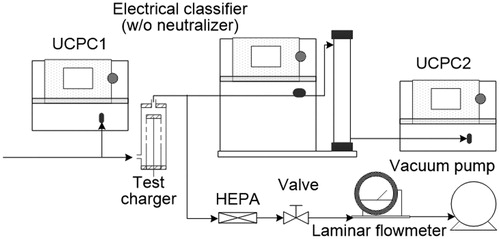
Neutral particles in a narrow size range were used as test particles (Chen et al. Citation2018). Polydisperse sodium chloride particles in the size range of 20–400 nm, generated by a custom-made Collison atomizer, were classified by a long DMA (TSI Model 3081) and the charging status of DMA-classified particles was conditioned to the stationary charge state in a home-made 210Po bipolar charger. Neutral particles in a narrow size range were obtained by removing charged particles out of the 210Po charger in a home-made electrostatic precipitator. The flow rates of the current unipolar charger were chosen to be 1.5 and 3.0 lpm based on the transmission efficiency of neutral particles (). shows the setup for measuring the concentration of singly charged particles exiting the current charger. The voltage of the DMA shown in was fixed to select singly charged particles whose concentration was measured by UCPC2 (Ultrafine Condensation Particle Counter, TSI Model 3776). The particle concentration upstream the charger was monitored by UCPC1, whose readings were applied to correct the measured downstream particle concentration for avoiding the influence of the upstream concentration variation. The corrected concentration of singly charged particles (Cscp) was directly related to singly charged fraction, f(+1), of particles and was used in the maximization of singly charged fraction of particles exiting the charger via the control of the corona current, Ic, and ion-driving voltage, Ud. A vacuum pump, with a valve and laminar flowmeter, were used to balance the flow rate in the setup. The singly charged fraction of monodisperse particles exiting the charger was measured by the method described in the work of Chen et al. (Citation2018) and briefly described in Appendix C in the SI.
Figure 4. Schematic diagram of the experimental setup for measuring the concentration of singly charged particles.
4. Result and discussion
4.1. Ion concentration control via the corona current and ion-driving voltage
As aforementioned, the ion concentration in the charging zone of the current charger could be controlled either by varying the corona-discharge current or ion-driving voltage. Given in is the relative singly-charged particle concentration, Cr,scp, as a function of either ion-driving voltage (the upper abscissa) or the corona-discharge current (the lower abscissa) at the flow rate of 1.5 lpm. The relative concentration of singly charged particles Cr,scp, is defined as the ratio of Cscp to Cscp,0, which is the singly charged particle concentration when the corona current is 0.4 μA and the ion-driving voltage is zero. In the investigation of the change of Cr.scp due to the ion-driving voltage, the corona-discharge current was kept at 0.4 μA. In the study of Cr.scp as a function of the corona-discharge current, the ion-driving voltage was set to zero. Limited by the requirement of stable corona current, the tested corona-discharge current ranged from 0.4 to 3.5 μA.
Figure 5. Effect of corona current and ion-driving voltage on the relative concentration of singly charged particles in the size of 60 nm (a) and 200 nm (b). The charger was operated at the flow rate of 1.5 lpm.
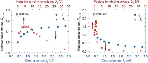
It was found that the Cr,scp (relative concentration of singly charged particles) of particles in the size of 60 nm increased with the increase of corona-discharge current. The opposite trend was obtained for particles in the size of 200 nm. The trend of Cr,scp represented the trend of singly charged fractions. Large particles can easily attain multiple charges compared to small particles under the same ion concentration. The ion-driving voltage was set as zero, thus the corona-discharge current is required to increase for improving the charging efficiency for small particles, but is required to decrease for reducing multiple charges on large particles. Unfortunately, the maximum Cr,scp value could not be achieved in the tested corona-discharge current range at the zero ion-driving voltage.
The ion concentration in the charging zone of the current charger can also be varied via the change of ion-driving voltage. The DC ion-driving voltage in both polarities can be applied in the current charger to increase or decrease the ion concentration in the charging zone. For the same reason described in the above paragraph, more ions are required to achieve the maximum Cr.scp value for small particles, so a higher negative ion-driving voltage on the charger case should be applied. While fewer ions are required to accomplish the same task for large particles, then a smaller negative voltage or even a positive ion-driving voltage should be applied. As shown in for particles in the size of 60 nm, negative ion-driving voltage was applied to increase the ion concentration in the charging zone. The maximum Cr,scp was achieved at the ion-driving voltage of −4 V. As evidenced in , the ion concentration in the charging zone was required to be reduced by applying positive ion-driving voltage in order to reach the maximum Cr,scp for 200 nm particles.
It is concluded that a wide range of ion concentration in the charging zone of the current charger can be varied via ion-driving voltage in both polarities for reaching the maximum Cr.scp compared to that via the the corona current. According to the above conclusion, tuning the ion-driving voltage was selected as the primary means to control ion concentration in the charging zone of the current charger.
4.2. Optimal ion-driving voltage
The optimal ion-driving voltage could be identified from the data set such as that shown in , which was corresponding to the achievable maximum relative concentration of singly charged particles. The above data sets were obtained for different particle sizes and at the flow rates of 1.5 and 3.0 lpm. The corona current was kept as 0.4 μA. We defined the optimal ion-driving voltage range as the range of voltage resulting in the relative concentrations of singly charged particles greater than 95% of the maximum Cr,scp. The optimal ion-driving voltage ranges at various particle sizes are summarized in ( are for 1.5 and 3.0 lpm, respectively). As found in , for maximizing the singly charged fraction of particles, negative ion-driving voltages should be applied to increase the charging efficiency for particles in the sizes <100 nm, while positive voltage was required for larger particles to reduce multiple charging.
Figure 6. Optimal ion-driving voltage and voltage range obtained in the experiment as a function of particle size when the charger was operated at the flow rates of 1.5 lpm (a) and 3.0 lpm (b).
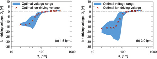
The ion-driving voltage increased, and the voltage range narrowed with the increase of particle size when the particle sizes were larger than 40 and 50 nm at the flow rates of 1.5 and 3.0 lpm, respectively. At the same flow rate, which means the same residence time in the charging zone, more ions are required to charge particles of small sizes, resulting in applying a higher negative voltage on the charger case. As the particle size increases, lower ion concentration is required in the charging zone to minimize multiple charges on particles, leading to applying a higher positive voltage on the charger case. For the narrowing of optimal ion-driving voltage range, it is probably caused by the non-linear relationship between the ion concentration in the charging zone and ion-driving voltage, which need further investigation.
For particles in sizes <40 nm in the case of 1.5 lpm flow rate, and 50 nm in the case of 3.0 lpm flow rate, the experimental data showed that the optimal driving voltage remained nearly constant and the voltage range became narrowed as the particle size decreased. This could be attributed to the severe loss of charged particles as the negative ion-driving voltage increases, which is also demonstrated in .
Probably because of the reduced particle residence time at the high flow rate, ion concentration in the charging zone of the charger would increase for achieving the same Nit product for particle charging, resulting in a higher negative or lower positive driving voltage. The similar observation is also found in .
4.3. Singly charged fraction of particles
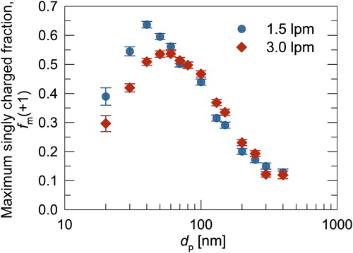
shows the measured fm(+1) (maximum singly charged fraction) of monodisperse particles as a function of particle sizes at two chosen flow rates. Notice that the fm(+1) for each particle size is corresponding to a different optimal ion-driving voltage applied to the current charger while the corona-discharge current was kept at 0.4 μA. For a given flow rate, the singly charged fraction of monodisperse particles increased and then decreased as the particle size increased. For the reference, the intrinsic and extrinsic charging efficiency of particles could be found in and the method to measure it is given in Appendix C.
Figure 7. Maximum singly charged fraction of particles as a function of particle size at the flow rates of 1.5 lpm and 3.0 lpm.
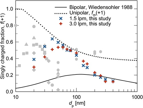
compares measured fm(+1) (maximum singly charged fraction) with f(+1) (singly charged fraction) in bipolar charging (Wiedensohler Citation1988), fm(+1) calculated by the birth-and-death model, and f(+1) reported by other studies. In general, the achieved fraction of singly charged monodisperse particles in the current charger is higher than that in a bipolar charger for particles in the size range of 20–200 nm. Especially for particles with the sizes ranging from 40 to 100 nm, the measured fm(+1) approximately approached those calculated in the model. For particles in the sizes <40 nm, the diffusional and electrostatic particle loss led to the lower singly charged fraction of particles compared with that given by the model. For particles with sizes larger than 100 nm, multiple charges on particles made it difficult to achieve the calculated fm(+1). In conclusion, the control of DC ion-driving voltage to vary the ion concentration in the charging zone of a unipolar charger for maximizing the fraction of singly charged monodisperse particles is feasible and is a simple and effective way to increase the fraction of singly charged monodisperse particles, especially in the ultrafine size range.
Figure 8. Comparison of the maximum singly charged fraction of particles achieved in the experiment and modeling with singly charged fractions achieved by bipolar charging (Wiedensohler Citation1988) and reported in the previous studies. Gray symbols are measured singly charged fractions via unipolar charging in previous studies (see for details).
5. Conclusion
The objective of this work is to explore the feasibility of maximizing the fraction of singly charged particles in a unipolar charger. The modeling of unipolar diffusion charging shows that the maximum fraction of singly charged monodisperse particles can be achieved at an optimal Nit product (where Ni is ion concentration and t is the particle residence time in the charging zone of a charger). The maximum fraction of singly charged monodisperse particles decreases as the particle size increases.
A unipolar corona charger was constructed for the experimental investigation. The ion concentration in the charging zone was controlled by either varying the corona-discharge current or ion-driving voltage. It was found that the range of ion concentration tuned via the control of ion-driving voltage was wider than that offered by corona-discharge current. The maximum fraction of singly charged monodisperse particles in the current charger was measured at different particle sizes and at the flow rates of 1.5 and 3.0 lpm. The current charger achieved higher singly charged fractions of particles than bipolar chargers for particles in the particle size range of 20–200 nm. Particularly in the size range of 40–100 nm, the measured fraction of singly charged particles was close to the data obtained in the model.
Supplemental Material
Download Zip (105.8 KB)Acknowledgments
We would like to thank the editor and three anonymous reviewers for valuable comments and suggestions to help improve this article.
Disclosure statement
No potential conflict of interest was reported by the authors.
Additional information
Funding
References
- Alguacil, F. J., and M. Alonso. 2006. Multiple charging of ultrafine particles in a corona charger. J. Aerosol Sci. 37 (7):875–884. doi: 10.1016/j.jaerosci.2005.08.007.
- Biskos, G., K. Reavell, and N. Collings. 2005. Unipolar diffusion charging of aerosol particles in the transition regime. J. Aerosol Sci. 36 (2):247–265. doi: 10.1016/j.jaerosci.2004.09.002.
- Boisdron, Y., and J. R. Brock. 1970. On stochastic nature of acquisition of electrical charge and radioactivity by aerosol particles. Atmospheric Environment 4 (1):35–50. doi: 10.1016/0004-6981(70)90052-1.
- Chen, B. T., H. C. Yeh, and N. F. Johnson. 1996. Design and use of a virtual impactor and an electrical classifier for generation of test fiber aerosols with narrow size distributions. J. Aerosol Sci. 27 (1):83–94. doi: 10.1016/0021-8502(95)00537-4.
- Chen, D.-R., and D. Y. H. Pui. 1999. A high efficiency, high throughput unipolar aerosol charger for nanoparticles. J. Nanoparticle Res. 1 (1):115–126. [Mismatch] doi: 10.1023/a:1010087311616.
- Chen, X. T., Q. L. Liu, J. K. Jiang, and D. R. Chen. 2018. Performance of small plate and tube unipolar particle chargers at low corona current. Aerosol Air Quality Res. 18 (8):2005–2013. doi: 10.4209/aaqr.2018.02.0060.
- Fuchs, N. A. 1963. On the stationary charge distribution on aerosol particles in a bipolar ionic atmosphere. Geofisica Pura e Applicata 56 (1):185–193. doi: 10.1007/BF01993343.
- Gupta, A., and P. H. McMurry. 1989. A device for generating singly charged particles in the 0.1-1.0-μm diameter range. Aerosol Sci. Technol. 10 (3):451–462. doi: 10.1080/02786828908959285.
- Han, B., M. Shimada, M. Choi, and K. Okuyama. 2003. Unipolar charging of nanosized aerosol particles using soft X-ray photoionization. Aerosol Sci. Technol. 37 (4):330–341. doi: 10.1080/02786820390125197.
- Hewitt, G. W. 1957. The charging of small particles for electrostatic precipitation. Trans. Amer. Inst. Elect. Eng. I (Commun. Electron.) 76:300–306. doi: 10.1109/TCE.1957.6372672.
- Hoppel, W. A., and G. M. Frick. 1986. Ion-aerosol attachment coefficients and the steady-state charge distribution on aerosols in a bipolar ion environment. Aerosol Sci. Technol. 5 (1):1–21. doi: 10.1080/02786828608959073.
- Hsiao, T. C., Y. C. Lee, K. C. Chen, W. C. Ye, K. Sopajaree, and Y. I. Tsai. 2016. Experimental comparison of two portable and real-time size distribution analyzers for nano/submicron aerosol measurements. Aerosol Air Quality Res. 16 (4):919–929. doi: 10.4209/aaqr.2015.10.0614.
- Hussin, A., H. G. Scheibel, K. H. Becker, and J. Porstendorfer. 1983. Bipolar diffusion charging of aerosol particles - I: Experimental results within the diameter range 4-30 nm. J. Aerosol Sci. 14 (5):671–677. doi: 10.1016/0021-8502(83)90071-x.
- Intra, P., and N. Tippayawong. 2011. An overview of unipolar charger developments for nanoparticle charging. Aerosol Air Quality Res. 11 (2):187–209. doi: 10.4209/aaqr.2010.10.0082.
- Knutson, E. O., and K. T. Whitby. 1975. Aerosol classification by electric mobility: Apparatus, theory, and applications. J. Aerosol Sci. 6 (6):443–451. doi: 10.1016/0021-8502(75)90060-9.
- Li, L., and D.-R. Chen. 2011. Performance study of a DC-corona-based particle charger for charge conditioning. J. Aerosol Sci. 42 (2):87–99. doi: 10.1016/j.jaerosci.2010.12.001.
- Marquard, A., J. Meyer, and G. Kasper. 2006a. Characterization of unipolar electrical aerosol chargers - Part I - A review of charger performance criteria. J. Aerosol Sci. 37 (9):1052–1068. doi: 10.1016/j.jaerosci.2005.09.001.
- Marquard, A., J. Meyer, and G. Kasper. 2006b. Characterization of unipolar electrical aerosol chargers - Part II: Application of comparison criteria to various types of nanoaerosol charging devices. J. Aerosol Sci. 37 (9):1069–1080. doi: 10.1016/j.jaerosci.2005.09.002.
- Ock, Y., J. Kim, I. Choi, D. S. Kim, M. Choi, and D. Lee. 2018. Size-independent unipolar charging of nanoparticles at high concentrations using vapor condensation and its application for improving DMA size-selection efficiency. J. Aerosol Sci. 121:38–53. doi: 10.1016/j.jaerosci.2018.04.007.
- Pui, D. Y. H., S. Fruin, and P. H. McMurry. 1988. Unipolar diffusion charging of ultrafine aerosols. Aerosol Sci. Technol. 8 (2):173–187. doi: 10.1080/02786828808959180.
- Qi, C., D.-R. Chen, and P. Greenberg. 2008. Performance study of a unipolar aerosol mini-charger for a personal nanoparticle sizer. J. Aerosol Sci. 39 (5):450–459. doi: 10.1016/j.jaerosci.2008.01.003.
- Qi, C., D.-R. Chen, and D. Y. H. Pui. 2007. Experimental study of a new corona-based unipolar aerosol charger. J. Aerosol Sci. 38 (7):775–792. doi: 10.1016/j.jaerosei.2007.05.005.
- Tavakoli, F., J. P. R. Symonds, and J. S. Olfert. 2014. Generation of a monodisperse size-classified aerosol independent of particle charge. Aerosol Sci. Technol. 48 (3):I–IV. doi: 10.1080/02786826.2013.877121.
- Vivas, M. M., E. Hontañón, and A. Schmidt-Ott. 2008. Reducing multiple charging of submicron aerosols in a corona diffusion charger. Aerosol Sci. Technol. 42 (2):97–109. doi: 10.1080/02786820701787969.
- Wiedensohler, A. 1988. An approximation of the bipolar charge distribution for particles in the submicron size range. J. Aerosol Sci. 19 (3):387–389. doi: 10.1016/0021-8502(88)90278-9.