
 ?Mathematical formulae have been encoded as MathML and are displayed in this HTML version using MathJax in order to improve their display. Uncheck the box to turn MathJax off. This feature requires Javascript. Click on a formula to zoom.
Abstract
© 2020 American Association for Aerosol Research
EDITOR:
1. Introduction
Several particle control technologies have been developed over the years to reduce our exposure to airborne particles that cause various health problems. Commercially, high-efficiency particulate air (HEPA) filtration and electrostatic precipitators (ESPs) are used to remove aerosol particles and inactivate bioaerosols (including several viruses) from the air in many indoor environments, including hospitals, offices, and aircraft cabins (Kettleson et al. Citation2009). However, both of these technologies have serious limitations. HEPA filtration systems usually result in excessive operational costs, as the media filter in these systems need regular replacement and the large pressure drop requires additional power for air circulation (Gupta et al. Citation1993). Electrostatic precipitators (ESPs) are more economical, but have size-dependent collection efficiencies, and in particular, the efficiency in the nanometer size range is typically low because nanoparticles are difficult to charge (Zhuang et al. Citation2000; Watanabe et al. Citation1995). Many potentially harmful indoor aerosols such as viruses (including the SARS-COV-2 virus) and protein fragments lie in the nanometer size ranges (Burnouf et al. Citation2005), and it is therefore critical to modify existing technologies or develop low-cost alternatives that efficiently capture harmful, nanometer-sized aerosols.
In an ESP, aerosol particles are charged by gaseous ions that are typically produced by a corona discharge, which is a type of localized plasma created near an electrode surface by the partial breakdown of a gas in the presence of a relatively strong electric field (Covert et al. Citation1997). Glow discharges are plasmas that are formed by complete gas breakdown and contain higher concentration of ions (Braithwaite Citation2000; Tendero et al. Citation2006). Several reactive species present in glow discharges also have promise for directly inactivating pathogens (Wang et al. Citation2017). Moreover, it is very easy to integrate flow-through versions of glow discharges operated at atmospheric pressure with existing particle control systems, to potentially address the charging efficiency of nanoparticles. However, few studies exist on these types of plasmas for particle charging and particle control applications. Ion mobility spectrometry has been applied online to flow-through plasmas at atmospheric pressure (Sankaran et al Citation2005) and low pressure (Chen et al Citation2018; Chen et al Citation2020) and observed the presence of bipolarly charged silicon nanoparticles after the spatial afterglow. Recently, Sharma et al. (Citation2020) systematically characterized particle charging in AC- and RF-powered flow-through, atmospheric-pressure, plasma systems. High charging efficiencies (>90%) were found for particles larger than 100 nm. However, the charging efficiency of particles smaller than 100 nm was low, with a charging efficiency of less than 40% for 20 nm sized particles and 0% for particles of size 10 nm. The charge distribution of particles exiting the plasma reactor was revealed to be bipolar with particles supporting multiple charges. A two-stage charging mechanism based on a characteristic time scale analysis suggested that while particles were predominantly charged negatively in the plasma volume, the relatively faster rate of loss of the electrons in the spatial afterglow (downstream of the plasma region) resulted in neutralization by positive ions, and even subsequent positive charging of some of the particles (Sharma et al. Citation2020). The effect was found to be larger for smaller particles because of their lower initial negative charge in the plasma volume. A potential strategy to improve the charge efficiency in these systems is to preserve the charging from the plasma volume by eliminating the ion-mediated neutralization in the spatial afterglow.
In this work, we present a new design concept for aerosol nanoparticle charging in plasmas: a DC field downstream of the plasma volume in the spatial afterglow to potentially remove the positive ions and prevent neutralization of the particles. To test the concept, magnesium sulfate (MgSO4) nanoparticles generated by atomization were introduced into a RF-powered, flow-through, atmospheric-pressure plasma and the overall charge fraction and charge distribution in terms of polarity were measured as a function of particle diameter at different downstream DC voltages. We find that when the magnitude of the applied DC voltage was higher (more negative) than −0.5 kV, the charge fraction of particles increased, and the charge polarity shifted from bipolar to unipolarly negative. The results were supported by analyzing the characteristic timescales for neutralization by and loss to the walls of positive ions in the spatial afterglow at different downstream DC voltages.
2. Materials and methods
2.1. Aerosol generation and plasma reactor
Aerosol nanoparticles were generated by atomizing solution mixture of MgSO4 (≥99% pure, Sigma Aldrich) dissolved in DI water using a TSI Aerosol Generator (Model 3076) with argon (Ar) as the carrier gas (≥99.998% pure, Sigma Aldrich). The atomized droplets were passed through a diffusion dryer to remove water and yield dry MgSO4 nanoparticles. The salt concentration in the atomized solution was adjusted to control the size of particles in the sub-100 nm range; in our experiments, a geometric mean diameter of 40 nm was used. Following the diffusion dryer and upstream of the plasma reactor, the particle stream was passed through a charged particle remover (Upstream CPR) to ensure that the particles entering the plasma were initially charge neutral. The flow rate of the particle stream was maintained at 1 L/min through the plasma reactor.
The plasma reactor schematically shown in was a flow-through system consisting of a clear fused quartz tube (ID: 2 mm, OD: 3.2 mm) and three metal ring electrodes on the outside in a parallel configuration. Two electrodes were electrically connected to a RF power supply (RF VII Inc., Model RF-3 XII), with one outer electrode connected to the power side through a homemade L-type matching network and the middle electrode connected to electrical ground. The spacing between these electrodes was 2 cm. The other outer electrode spaced apart by 1.2 cm from the middle electrode was connected to the high voltage output of a DC power supply which shared the same electrical ground.
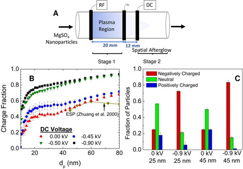
Figure 1. (a) Schematic illustration of the RF-powered, flow-through, atmospheric-pressure plasma reactor with downstream DC bias used to study aerosol nanoparticle charging. (b) Charge fraction of aerosolized MgSO4 nanoparticles measured after plasma reactor as a function of particle diameter and different DC biases. The collection efficiency of aerosolized NaCl particles measured after an ESP reported by Zhuang et al. (Citation2000) is shown for comparison. (c) Charge fraction of aerosolized MgSO4 nanoparticles with 25 and 45 nm diameter after plasma reactor as a function of DC bias polarity.
2.2. Charge characterization
We systematically characterized the effect of a downstream DC bias on particle charging in a flow-through, atmospheric-pressure, RF plasma. Particle charging was assessed by the charging efficiency, which is defined as the fraction of particles that are charged, or the ratio of particles that attain any charge (either positive or negative, single or multiple) to the total number of particles entering the plasma. To measure the particle charge, the aerosol flow leaving the spatial afterglow was diluted by air at a flow rate of 2 L/min. The particle size distribution (PSD) and the charged particle fraction (either polarity) exiting the plasma reactor was obtained via a combination of a second charged particle remover (downstream CPR) and a scanning mobility particle sizer (SMPS). The initial PSD produced by the atomizer was measured in terms of a mobility diameter by the SMPS with the plasma and downstream CPR off. When the plasma and the downstream CPR were both turned on, the charge neutral (uncharged) PSD was obtained. The charged particle fraction was finally calculated by subtracting the ratio of the neutral PSD and the initial PSD from unity. A similar charge characterization was then performed for different DC voltages in the spatial afterglow.
The polarity of particle charge exiting the plasma reactor was measured using a tandem differential mobility analyzer (TDMA) setup, consisting of two DMAs, a neutralizer, and a condensation particle counter (CPC). Details of the procedure have been previously reported in Sharma et al. (Citation2020). Here, we focused on the polarity of particles at two mean mobility diameters, 25 and 45 nm, as a function of the downstream DC voltage.
3. Results and discussion
3.1. Charging characteristics
The charging of particles exiting the plasma was initially characterized by the charged particle fraction. The DC voltage, applied to the third electrode, was varied to gauge the effect of downstream DC bias on particle charging. shows the charge fraction of MgSO4 particles exiting the RF plasma as a function of mobility diameter at different DC voltages. It can be seen from that charge fraction increases with increasing diameter. At zero DC voltage, the charge fraction of 10 nm particles is nearly zero; it increases to about 40% as the diameter increases to 20 nm, and is nearly 70% for 80 nm particles. shows that increasing the DC voltage from 0 kV to −0.45 kV does not result in significant difference in the total fraction of charged particles. A significant increase in charge fraction is observed when the DC voltage is increased to −0.5 kV. At an applied DC voltage of −0.5 kV, the charge fraction increases to nearly 35% for 10 nm particles, 70% for 20 nm particles and greater than 95% for 80 nm particles. Thus, −0.5 kV appears to be a threshold at which the charged particle fraction is enhanced. Any additional increase in DC voltage did not result in further change to the charged particle fraction.
In order to further understand the effect of downstream DC bias on particle charging, we characterized the polarity of the charge. shows the charge distribution on MgSO4 particles with 25 and 45 nm mean mobility diameters exiting the plasmas at two different DC voltages. At a DC voltage of 0 kV, the particles exhibit a bipolar charge distribution, which can be attributed to a two-stage charging mechanism in the plasma reactor that was previously reported (Sharma et al. Citation2020). Briefly, particles first acquire a predominantly negative charge in the plasma volume and subsequently, in the spatial afterglow, electrons are lost faster to the walls as compared to the positive ions because of their higher mobility, resulting in a larger flux of positive ions to the particles and neutralization. As can be seen from , if a DC voltage of −0.9 kV is applied in the spatial afterglow, the fraction of positively charged particles becomes nearly zero and the particles are predominantly negatively charged. A possible explanation is that the negative DC bias decreases the flux of electrons or increases the flux of positive ion to the walls and thus, limits or even eliminates neutralization of the particles, preserving the predominantly negative charge state of the particles leaving the plasma volume.
The distance between the third electrode with a DC bias and the ground electrode was also varied. At a distance of 1.2 cm, the critical DC voltage where particle charging efficiency was observed to dramatically increase was −0.5 kV. On increasing the electrode distance to 1.8 cm, the critical DC voltage increased to −2.5 kV, and at 2.4 cm, the DC bias was found to be ineffective up to a maximum of −5 kV. The experiments were also performed for positive DC bias; however, a positive DC voltage in the spatial afterglow was not found to have any effect on the charging characteristics of particles as compared to no bias. We note that the magnitudes of the DC voltages reported here could depend on many factors including the flow rate, reactor/electrode geometry, chemical composition of carrier gas, etc., but the overall trends should remain the same.
3.2. Characteristic time scale analysis
The experimental measurements indicate that the application of a negative DC field in the spatial afterglow reduces neutralization of particles, likely by decreasing the loss of electrons or increasing the loss of positive ions to the walls. To support and provide additional insight, the characteristic time for neutralization was compared to the characteristic loss time of positive ions as a function of the applied DC voltage. First, the electric potential distribution in the spatial afterglow was calculated using COMSOL. Then, while accounting for drag and electrical forces, Newton’s second law (force balance expression) was solved to get the trajectory of the positive ions in the spatial afterglow and calculate the characteristic loss time of positive ions (). The neutralization of negatively charged particles in the spatial afterglow, was modeled using Fuchs theory of particle charging. The characteristic neutralization time (
) was estimated by
(1)
(1)
Here, is the ion attachment coefficient signifying the rate of collision of particle of charge q and size dp, and
is the number concentration of positive ions in the spatial afterglow. Briefly, the charge attained by particles in the plasma volume was estimated first, and then using Fuchs theory of particle charging, the ion attachment coefficient was calculated. We note that the particle size could affect the neutralization time in spatial afterglow as larger particles possess more charge and would require more collisions or more time to be neutralized. We chose the 40 nm mobility diameter particles as a representative size to estimate the ion attachment coefficient. Sharma et al. (Citation2020) reported the ion density in the same RF, flow-through, atmospheric-pressure plasma to be about 1020 m−3. The ion concentration in the spatial afterglow should be several orders of magnitude lower due to wall losses and electron-ion concentration recombination. However, the exact concentration is not known, and further experiments are required to measure it. For our purposes here, we varied the concentration and determined that a concentration of 2.5 × 10¹⁵ m−3 provided the best agreement between our characteristic time analysis and experimental results (SI Figure S4), which is consistent with the expected lower concentration than the plasma volume and literature values for an afterglow (Xu and Doyle Citation2016). Details for the calculations of
and
can be found in the online supplementary information.
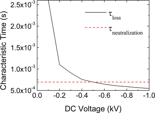
shows that the characteristic time of positive ion loss to the walls in the spatial afterglow region decreases as the magnitude of the DC voltage increases (more negative). When the DC voltage is −0.5 kV or higher (more negative), the characteristic neutralization time for negatively charged particles is longer than the time for loss of positive ions. Therefore, the charge fraction of particles will be higher, as the positive ions are lost relatively faster than the time required for particles to be neutralized, in agreement with experimental measurements. also shows that consistent with experiments, there is no further enhancement in positive ion removal rate as the DC voltage is increased beyond −0.5 kV.
Figure 2. Calculations of characteristic times for positive ions colliding with and being lost to the reactor walls and colliding with and neutralizing negatively charged nanoparticles in the spatial afterglow as a function of the DC bias voltage.
3.3. Proposed mechanism
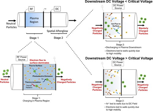
We have previously proposed that particle charging in a flow-through, atmospheric-pressure plasma reactor is a two-stage process. The particles first pass through plasma volume which is quasi-neutral. Particles are predominantly charged negatively inside the plasma region because of the higher mobility of electrons compared to other charged species. The negative charge on particles in the plasma region will increase as the function of their size as larger particles are capable of holding more charge. After passing through the plasma volume, the particles exit through the spatial afterglow region (Liu et al. Citation2015; Couëdel et al. Citation2008; Wörner et al. Citation2013), which is the region outside the RF and ground electrodes where ionization no longer takes place, but charged species remain (Liu et al. Citation2015). In the spatial afterglow, electrons are quickly lost to the walls due to their very high mobility. Based on the experimental results and characteristic time scale analysis, the fate of negatively charged particles in the afterglow depends on the magnitude of DC voltage applied to the third electrode, as shown in . When there is no DC voltage or it is less than a critical voltage (less negative), loss of positive ions to the walls is relatively slow as compared to the characteristic neutralization time of the negatively charged particles. Because of this, the negatively charged particles exiting the plasma volume are neutralized and charged positively. This results in a bipolar distribution of charge on the particles at the reactor outlet. The neutralization effect was found to be larger for smaller particles because of their lower initial negative charge in the plasma region. However, when the applied DC voltage is higher than a critical voltage (more negative), the positive ions are lost to the walls relatively faster as compared to the characteristic neutralization time. In this case, positive ions are removed and unable to neutralize the negatively charged particles exiting the plasma volume. Therefore, the particles retain their negative charge at the reactor outlet, and the fraction of particles carrying a charge is higher. The charge fraction increases with particle size as larger particles get higher initial negative charged inside the plasma region. Although the proposed mechanism is supported by characteristic time calculations, other mechanisms could also be responsible for the experimental observations and were not considered in this study. We note that a similar picture could be described based on the DC voltage higher than a critical voltage (more negative) slowing the loss of electrons to the walls. Also, thermionic emission from quartz wall can take place near the DC electrode due to high temperature and application of negative electric field, which reduces the work function. Future studies are needed to verify the mechanism or the combination of mechanisms that affect particle charging in the afterglow region under the influence of negative electric field.
Figure 3. Schematic illustration of the two key particle charging regimes that exist in a RF, flow-through, atmospheric-pressure plasma reactor with downstream DC bias: one, the main plasma volume where nanoparticles are predominantly charged negatively by the higher mobility electrons, and two, the spatial afterglow where positive ions neutralize and/or charge positively the negatively charged particles when the DC bias voltage is less than a critical voltage, or where positive ions are removed and the negatively charged particles are preserved above a critical voltage.
When the DC voltage was higher than the critical voltage, the overall charge fraction of particles was found to be very high for sub-100 nm particles, with a charging efficiency greater than 95% for 80 nm particles and greater than 70% for 20 nm particles. As can be seen from , these efficiencies are very high as compared to traditional ESPs (Zhuang et al. Citation2000) which highlight the potential application of our flow-through, atmospheric-pressure plasma reactor with DC bias as a particle control device. Alternatively, the plasma reactor could be easily integrated with existing particle control systems to enhance their efficiencies at the smaller particle sizes. Moreover, further study of the potential inactivation of pathogens by the plasma could potentially lead to additional benefits.
Supplemental Material
Download MS Word (873.7 KB)Additional information
Funding
References
- Braithwaite, N. S. J. 2000. Introduction to gas discharges. Plasma Sources Sci. Technol. 9 (4):517–27. doi:10.1088/0963-0252/9/4/307.
- Burnouf, T., M. Radosevich, H. A. Goubran, and H. Willkommen. 2005. Place of nanofiltration for assuring viral safety of biologicals. Cnano. 1 (3):189–201. doi:10.2174/157341305774642894.
- Chen, X., S. Ghosh, D. T. Buckley, R. M. Sankaran, and C. J. Hogan. Jr.2018. Characterization of the state of nanoparticle aggregation in non-equilibrium plasma synthesis systems. J. Phys. D: Appl. Phys. 51 (33):335203. doi:10.1088/1361-6463/aad26f.
- Chen, X., T. Seto, U. R. Kortshagen, and C. J. Hogan. Jr.2020. Size and structural characterization of Si nanocrystal aggregates from a low pressure nonthermal plasma reactor. Powder Technol. 373:164–73. doi:10.1016/j.powtec.2020.06.026.
- Couëdel, L., A. A. Samarian, M. Mikikian, and L. Boufendi. 2008. Dust charge distribution in complex plasma afterglow. Europhys. Lett. 84 (3):35002. doi:10.1209/0295-5075/84/35002.
- Covert, D., A. Wiedensohler, and L. Russell. 1997. Particle charging and transmission efficiencies of aerosol charge neutralizes. Aerosol Sci. Technol. 27 (2):206–14. doi:10.1080/02786829708965467.
- Gupta, A., V. J. Novick, P. Biswas, and P. R. Monson. 1993. Effect of humidity and particle hygroscopicity on the mass loading capacity of high efficiency particulate air (HEPA) filters. Aerosol Sci. Technol. 19 (1):94–107. doi:10.1080/02786829308959624.
- Kettleson, E. M., B. Ramaswami, C. J. Hogan, Jr, M. H. Lee, G. A. Statyukha, P. Biswas, and L. T. Angenent. 2009. Airborne virus capture and inactivation by an electrostatic particle collector. Environ. Sci. Technol. 43 (15):5940–6. doi:10.1021/es803289w.
- Liu, F. X., X. M. Guo, and Y. K. Pu. 2015. Electron cooling and plasma density decay in early afterglow of low pressure argon plasmas. Plasma Sources Sci. Technol. 24 (3):034013. doi:10.1088/0963-0252/24/3/034013.
- Sankaran, R. M., D. Holunga, R. C. Flagan, and K. P. Giapis. 2005. Synthesis of blue luminescent Si nanoparticles using atmospheric-pressure microdischarges. Nano Lett. 5 (3):537–41. doi:10.1021/nl0480060.
- Sharma, G., N. H. Abuyazid, S. Dhawan, S. Kshirsagar, R. M. Sankaran, and P. Biswas. 2020. Characterization of particle charging In low-temperature, atmospheric-pressure, flow-through plasmas. J. Phys. D: Appl. Phys. 53 (24):245204. doi:10.1088/1361-6463/ab7c97.
- Tendero, C., C. Tixier, P. Tristant, J. Desmaison, and P. Leprince. 2006. Atmospheric pressure plasmas: A review. Spectrochim. Acta B 61 (1):2–30. [Database] doi:10.1016/j.sab.2005.10.003.
- Wang, X. Q., R. W. Zhou, G. de Groot, K. Bazaka, A. B. Murphy, and K. K. Ostrikov. 2017. Spectral characteristics of cotton seeds treated by a dielectric barrier discharge plasma. Sci. Rep. 7 (1):1–9.
- Watanabe, T., F. Tochikubo, Y. Koizurni, T. Tsuchida, J. Hautanen, and E. I. Kauppinen. 1995. Submicron particle agglomeration by an electrostatic agglomerator. J. Electrostat. 34 (4):367–84. doi:10.1016/0304-3886(95)93833-5.
- Wörner, L., A. V. Ivlev, L. Couëdel, P. Huber, M. Schwabe, T. Hagl, M. Mikikian, L. Boufendi, A. Skvortsov, A. M. Lipaev, et al. 2013. The effect of a direct current field on the microparticle charge in the plasma afterglow. Phys. Plasmas 20 (12):123702. doi:10.1063/1.4843855.
- Xu, K. G., and S. J. Doyle. 2016. Measurement of atmospheric pressure microplasma jet with Langmuir probes. J. Vac. Sci. Technol. A 34 (5):051301. doi:10.1116/1.4959565.
- Zhuang, Y., Y. J. Kim, T. G. Lee, and P. Biswas. 2000. Experimental and theoretical studies of ultra-fine particle behavior in electrostatic precipitators. J. Electrost. 48 (3-4):245–60. doi:10.1016/S0304-3886(99)00072-8.