
 ?Mathematical formulae have been encoded as MathML and are displayed in this HTML version using MathJax in order to improve their display. Uncheck the box to turn MathJax off. This feature requires Javascript. Click on a formula to zoom.
Abstract
Resuspension of deposited particles, which can be inhaled by human respiratory system, has been identified as a major airborne contaminant source. This study develops a new probabilistic model combing a modified Markov chain and turbulent burst theory to predict resuspension of mono-deposited particles from flat surfaces. First, a steady-state turbulent flow field is calculated by using CFD models, and detailed information of the flow field are exported out to establish a modified Markov chain model. Then the turbulent burst theory is implemented to acquire resuspension probabilities between specific numerical subspaces. Finally, the proposed model is initialized for particle phase simulation. Two rectangle duct flow cases, in which mono-deposited particle are preloaded on the floor surface, are adopted to validate the proposed model. Good agreements between simulated and experimental data indicate that the proposed model has solid capability to predict/simulate particle resuspension. The effects of particle diameter, flow velocity and turbulent burst characteristic α on particle resuspension are investigated. Results show that the accuracy of the proposed model is influenced by α, and α is recommended to be increased with the increase of flow velocity under relatively wide ranges of flow velocities. The resuspension rate becomes almost constant over time as particle size and flow velocity decrease. The computational cost of the proposed model varies with grid resolution and resuspension probability expression, which is still less than that of conventional Lagrangian/Eulerian models. The proposed model has the potential to be an alternative choice to help understanding and improving indoor air quality.
Copyright © 2021 American Association for Aerosol Research
EDITOR:
1. Introduction
The term “resuspension,” so far, has been used to describe the re-entrainment of deposited particle into the surrounding circumstances. Resuspended particulate matters from surfaces are considered as one of the major sources of airborne contaminants. An inverse modeling study (And, Hopke, and Wallace Citation1999) showed that up to 30% of the particulate matter with diameters of less than 10 microns (PM10) originates from particle resuspension. As is well known to all, sub-micro airborne particles could be inhaled by human beings subsequently causing inverse health effects either in public or residential buildings (Wu et al. Citation2018). It is therefore of great importance to reveal the features of resuspension process of indoor deposited particles.
From a macro perspective, particle resuspension process can be induced by various disturbances (Gomes, Freihaut, and Bahnfleth Citation2007). For instance, walking has been identified as one of the crucial human activities causing particle resuspension (Ferro, Kopperud, and Hildemann Citation2004). Even though walking induced particle resuspension has been widely investigated, as reviewed by Qian et al. (Qian, Peccia, and Ferro Citation2014), there still exists many open questions in this field. Besides, a certain proportion of indoor resuspended particles can be attributed to the operation of HVAC systems in buildings (Krauter and Biermann Citation2007) and animal indoor activities (Arlian et al. Citation2001). In addition, impingement jet flows indoors like human coughing and sneezing might also become the potential causes of particle re-entrainment under specific circumstances (Mei, Zhang, and Wang Citation2016; Zuo, Zhong, and Kang Citation2015). Abovementioned disturbances can be generally classified into two types, namely aerodynamic disturbance and mechanical disturbance (or a combination of both). Among those complicated resuspension phenomena, it is reasonable to reveal the mechanism by studying a basic resuspension scenario, where particles are pre-deposited on a horizontal surface with ventilation background.
From a micro perspective, typically two main particle-surface interactive theories are adopted to explain the particle detachment process. The first one is the force/momentum balance or the so-called quasi-static theory (Reeks and Hall Citation2001; Ziskind, Fichman, and Gutfinger Citation1995), which believes that once the sum of the external forces exerted on a particle overcomes the sum of gravitational force and adhesion force, then the particle will begin to roll/slip or even directly lift off (resuspend). However, the quasi-static theory fails to consider the effects of turbulent burst, which is proved to be significant for particle-surface detachment within viscous sublayers. The second theory is the energy accumulation theory or the so-called dynamical theory (Reeks, Reed, and Hall Citation1988), which indicates that a single particle will resuspend until sufficient vibration energy is accumulated from various disturbances including turbulent burst. Compared with the quasi-static theory, the dynamical theory is more convincing in explaining practical resuspension phenomena. Moreover, the occurrence of turbulent burst within viscous sublayer is considered as a significant factor that triggers the resuspension process of deposited particles.
To comprehensively investigate the detachment and transport process of particle resuspension, various numerical methods are proposed (Liu et al. Citation2018). For instance, CFD is a powerful numerical tool which has been widely implemented in particle behavior simulations. Habchi et al. (Habchi, Ghali, and Ghaddar Citation2016) numerically investigate the resuspension of deposited monolayer particles by coupling analytical model with CFD model. Reasonable agreements between simulation results and experimental data indicate that the coupled model is able to capture principal factors affecting particle resuspension. Besides, stochastic approaches also show their advantages in predicting particle random behaviors including but not limited to resuspension. For example, to consider the stochastic nature of turbulent flow, Goldasteh et al. (Goldasteh, Ahmadi, and Ferro Citation2013) develop a Monte Carlo model for particle resuspension under turbulent flow condition. Henry et al. (Henry and Minier Citation2014) present a Lagrangian stochastic model to simulate colloid resuspension from rough surfaces. Liu et al. (Liu, You, and Chen Citation2019) investigate particle transient transport by combing the Markov chain model and Fast Fluid Dynamics, which is capable of greatly reducing computing cost while maintaining reasonable accuracy. Numerical models such as CFD model can provide detailed information of resuspension process, however, the computational costs are usually unacceptable in specific circumstances (such as under engineering situations). For the purpose of practical applications or fast prediction in possible emergency situations, more efficient and simplified models for particle resuspension should be proposed. Probabilistic models like Markov chain model may have the potential to realize fast prediction, but to the authors’ best knowledge by now, no research on particle resuspension by using Markov chain model has ever been reported.
The present study proposes a new probabilistic model by combining a modified Markov chain approach and the turbulent burst theory to predict resuspension of deposited particles from flat horizontal surface. In the proposed model, a modified Markov chain model is first established under a steady-state flow field. The probabilistic elements representing particle resuspension in the modified Markov chain model are determined and replaced by implementing the turbulent burst theory. To further accelerate the computing process, the so-called grid-merging operation (Mei et al. Citation2017) has also been adopted in the present study.
2. Methods
2.1. Construction of a modified markov chain model
As mentioned above, the newly proposed probabilistic model is primarily constructed by combing a modified Markov chain model and the turbulent burst theory. The Markov chain model is a widely accepted tool in solving problems arising from stochastic process, and it has been retrofitted and implemented in several studies for indoor particle passive transmission and deposition. In this section, we introduce the basic concept of the Markov chain model briefly and its modification form in detail. In a basic Markov chain model, aerosol transmission process in a ventilated space is considered as consecutively changed particle distributions from one state to another (Chen et al. Citation2014). If the initial state of particle distribution at time t is given in EquationEquation (1)(1)
(1) , thus any future target state after a specific time period Δt can be expressed as EquationEquation (2)
(2)
(2) :
(1)
(1)
(2)
(2)
where St, St+Δt are the state vectors indicating how many particles are in each pre-divided subspace of the computational domain at time t and time t + Δt, respectively. The positive number n represents the original number of subspaces, and the extra n + 1 subspace is defined as the space to store particles moving out of computational domain. A so-called State Transfer Matrix P, which is determined originally by the net flowrates between subspaces (Nicas Citation2000), is built to connect the current state vector St and the future state vector St+Δt as shown in EquationEquation (3)
(3)
(3) (Chen et al. Citation2015). And the conditions in EquationEquation (4)
(4)
(4) should also be satisfied for first-order Markov chain model.
(3)
(3)
(4)
(4)
where pij is the probability of a single particle moving from subspace i to its adjacent subspace j. EquationEquation (3)
(3)
(3) is the so-call one-step transfer process representing a basic Markov chain model. For multi-step transfer process, for instance k steps, the future state vector St+Δt equals to the product of current state vector St and Pk. In order to store initially deposited particles for the upcoming resuspension process in the present study, some extra subspaces are defined and added adjacent to floor surface as shown in . If resuspension occurs in vertical wall or ceiling, extra subspaces can also be added adjacent to those surfaces.
Figure 1. Diagram of the configuration of a 2D computational domain for particle passive transfer and resuspension.
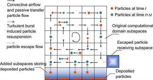
As depicted in , suspended particles within the original computational domain are passively transported by airflow from one subspace to another, but deposited particles are transported from the added subspaces to the original computational domain due to turbulent bursts. These extra added subspaces are defined not to receive deposited particles from original computational domain, which means particle deposition process is not considered in this article and may slightly reduce the accuracy of the proposed model (Due to deposition of detached particles, the simulated resuspension rate will be higher than realistic resuspension rate). The escaped particle receiving subspace is re-numbered as n+nadded+1, and transportation of particle from the specific subspace to any other region is not allowed. For 3D computational domain, the basic configurations and classifications of subspaces are similar to those in . The original State Transfer Matrix P can accordingly be extended and modified as the following form:
(5)
(5)
(6)
(6)
where nadd is the number of added subspaces to store deposited particles. Elements marked as black, red, green, purple and blue are all the probability expressions between/within subspaces in the original computational domain and the added subspaces. And those probabilities should be acquired in correct order as follows:
if 1 ≤ i ≤ n, 1 ≤ j ≤ n. Elements within this region marked as black have the same meaning as in EquationEquation (3)
(3)
If i= n+nadd+1, 1 ≤ j ≤ n+nadd+1. Elements within this region means the probabilities of particles moving from the escaped particle receiving subspace to the original computational domain, which is not allowed in the present study. In particular, the probability of particles remaining in the escaped particle receiving subspace after time period Δt equals to 1:
if 1 ≤ i ≤ n, n + 1 ≤ j ≤ n+nadd. Elements within this region are marked as blue, which represent the probabilities of particles moving from the original computational domain to added subspaces. Since particle deposition is not our primary concern, particle flows from boundary subspaces to the added subspaces (if any, marked as elements in blue) are not considered.
if n + 1 ≤ i ≤ n+nadd, 1 ≤ j ≤ n. Elements within this region are marked as red, which represent probabilistic expression of particles moving from added subspaces to the original computational domain. Acquiring exact probability expressions of these elements is the key task for the proposed probabilistic model, which will be elaborated in section 2.2 below.
if n + 1 ≤ i, j ≤ n+nadd, i ≠ j. Elements within this region are marked as green, which represent probabilities of particles moving between the added subspaces after time period Δt. In the present study, particle exchanges among extra added subspaces are limited practically therefore defined as zeros.
if n + 1 ≤ i, j ≤ n+nadd, i = j. Elements within this region are marked as purple, which represent probabilities of particles remaining in the same added subspaces after time period Δt. These elements can ultimately be estimated by solving EquationEquation (6)
2.2. Derivation of resuspension probabilities
Particles deposited on surface in this article are assumed to resuspend due to turbulent burst in airflow, and the impingement area of a single turbulent burst is considered to be circular (Cleaver and Yates Citation1973). A sketch of the shape and distributions of turbulent bursts is shown in .
Figure 2. Diagram of turbulent bursts on particle laden surface of a single subspace, the left part shows the top impingement view of several bursts and the right part shows the front view of a single burst.
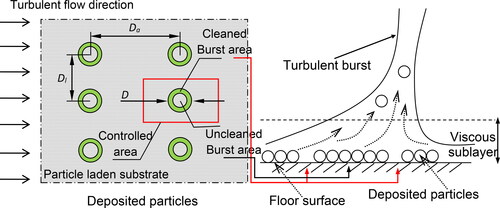
In , most of the deposited particles in the green area marked as cleaned burst aera are assumed to be removed by turbulent burst. During particle phase simulation, however, deposited particles are initially stored in those additionally added subspaces (blue blocks at the bottom) depicted in instead of laying on the floor surface in the right part of . The turbulent bursts occur with a random frequency and the mean time between two bursts Tburst (Cleaver and Yates Citation1973), which is crucial to the determination of the time step Δt between two consecutive state vectors (usually, Δt should be larger than Tburst in order to observe at least one burst physically), is defined as follows:
(12)
(12)
where νf is the dynamic viscosity of air defined as 1.55 × 10⁻⁵ m2/s, and u* is the flow friction velocity. As depicted in , the mean diameter D of the turbulent burst impingement area is defined as EquationEquation (13)
(13)
(13) by Cleaver and Yates(Cleaver and Yates Citation1973). The axial and the lateral spacing of a single turbulent burst controlled area, which is the rectangle part marked as red shown in , can be calculated by EquationEquation (14)
(14)
(14) and EquationEquation (15)
(15)
(15) , respectively (Cleaver and Yates Citation1973):
(13)
(13)
(14)
(14)
(15)
(15)
where u* is also the friction velocity of the flow previously depicted in EquationEquation (12)
(12)
(12) , and it is formally defined by the following equation:
(16)
(16)
where u∞ is the average air speed in the axial direction (or the so-called mainstream velocity in the present study, which can be obtained from flow field data pre-solved by CFD methods) and f is the Fanning friction factor. ρf is the fluid density with the value of 1.18 kg/m3. In a fully developed turbulent duct flow, Fanning friction factor f can be calculated as (White Citation1986):
(17)
(17)
where z0 is the mean microscale roughness height of the rough wall with the value of 5 × 10⁻³ m in the present study for grass material. Re is Reynolds number and Dh is hydraulic diameter, which is defined as the quotient of 4 times the cross-sectional area and the perimeter of the flow duct. Considering the fraction of a single turbulent burst in a single controlled area as constant, the total fraction of the burst areas on the particle laden surface is:
(18)
(18)
The fraction of particles resuspended by a single turbulent burst is α for uniformly deposited particles in the present study, then the fraction of resuspended particles from a horizontal flat surface by turbulent flow per unit time F can be calculated as:
(19)
(19)
The value of α can be estimated based on the assumption that it is proportional to the wall shear stress (Cleaver and Yates Citation1973). Based on that principle, Zhu et al. (Citation2012) proposed a formula to estimate the exact value of α:
(20)
(20)
where the uc* is the critical friction velocity under which particles begin to resuspend. Our tentative calculation results show that EquationEquation (20)
(20)
(20) based α is generally about 10−4. But as recommended in the research of Cleaver and Yates (Cleaver and Yates Citation1973), it is physically reasonable to assume α as 10−2. To have a proper estimation of α and its effects on model, here we introduce another value of α and modify EquationEquation (20)
(20)
(20) into another form as:
(21)
(21)
where the parameters in EquationEquation (21)
(21)
(21) are identical to those in EquationEquation (20)
(20)
(20) . Then the point is to find out the solution to the critical friction velocity uc*, which can be addressed by using the methods described in the research conducted by Theerachaisupakij et al. (Citation2003) and Zhu et al. (Citation2012). However, our primary concern is the derivation of particle resuspension probability, detailed calculation process of uc* is not presented here to avoid redundancy.
For uniformly deposited particles, the percentage of “uncleaned” area, which means the area without being disturbed by turbulent burst after a specific time period t, can be calculated by (Cleaver and Yates Citation1973):
(22)
(22)
From another perspective, the probability of deposited particles resuspended by a single turbulent burst after time period t (or at time point t) can be derived by combing EquationEquations (19)(19)
(19) and Equation(22)
(22)
(22) as:
(23)
(23)
where Premoval is the probability that varies with local flow/temporal characteristics such as the friction velocity u* as well as time t (or k × Δt). EquationEquation (23)
(23)
(23) can therefore be implemented to calculate the elements marked as red of the extended matrix P in EquationEquation (5)
(5)
(5) as follows:
(24)
(24)
where t is elapsed time equals to the product of time step size Δt and the number of time step sizes k, which has been previously mentioned in section 2.1. As can be seen, the probabilities of particle resuspension will be refreshed within each time step size Δt and last k times throughout the whole simulation period. It is also noted that the resuspension probability is inversely proportional to time, which is commonly agreed in other researches for long term resuspension process.
To evaluate the resuspension strength and particle dynamic process, a widely accepted parameter Particle resuspension rate R in the present study is used and defined by (Mortazavi Citation2005):
(25)
(25)
where N0 is the initial number of particles per unit area of the particle laden substrate, and N(t) is the number of particles per unit area of the substrate after a specific time t.
2.3. Validation case description and numerical procedure
To validate the proposed model as presented from EquationEquations (1)(1)
(1) to Equation(25)
(25)
(25) , data from an experiment study conducted by Nicholson (Nicholson Citation1993) are adopted (validation Case 1). The experiment is carried out by using a wind tunnel (or ventilation duct), as demonstrated in , with a 1 m × 1 m (H × W) cross section and the floor of the tunnel is made of concrete paving slabs or grass, but only the substrate made of grass is adopted in present study. It is known that different substrate materials usually result in different simulation parameters such as roughness height. But considering the page limitation, only one substrate type (grass) is presented. Readers who are interested may implement our proposed model to any other substrate types. The length of the wind tunnel L is 19.25 m. The feed particles are spherical and made of silica with a standard density of 1000 kg/m3. The diameters of the deposited particles are 4.1 ± 0.8 µm, 9.6 ± 1.9 µm, 17.5 ± 2.7 µm, and 22.1 ± 3.2 µm in the original experiment. The proposed model fails to take particle deposition into account since the resuspension phenomenon is our primary concern, so the size of chosen particles should be small enough to maintain the accuracy of the proposed model. Thus only the particles with diameters of 4.1 ± 0.8 and 9.6 ± 1.9 are adopted in this article. But if the methods/models developed in our previous study (Mei and Gong Citation2018) are implemented, the simulation of particle deposition process can be included. The data of validation Case 1 in the present study originate from the experimental research conducted by Nicholson (Nicholson Citation1993), where the tested velocity ranges from 3.0 m/s to 8 m/s (more specifically, 3, 4.5, 5, 6.5, and 8 m/s). To be roughly consistent with the velocity range and the chosen substrate type (grass), the maximum (3 m/s), the minimum (8 m/s) and one of the intermedium values (4.5 m/s) of flow speeds in the wind tunnel are selected.
Figure 3. Configuration of the ventilation duct for model validation Case 1 (particles are uniformly deposited on the floor surface).
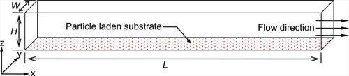
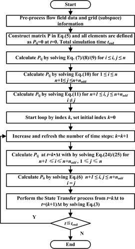
Figure 4. Numerical procedure of particle phase simulation by using the proposed model.
Flow field in the ventilation duct is solved in advance by using the CFD software, then the parameters including velocity components, turbulent kinetic energy and the coordinates of all subspace nodes and surfaces are exported out as data files. For flow field simulation in indoor/enclosed environment, RNG k-ε turbulence model has been proved to show the best overall performance among various RANS model (Zhang et al. Citation2013; Zhang et al. Citation2007). Both LES (Large Eddy Simulation) and DNS (Direct Numerical Simulation) models, however, can provide more detailed flow information while consuming much more computational resources than RANS models. For a confined one-way tunnel flow in the present simulation case, the accuracy and applicability of RNG k-ε turbulence model is good enough and therefore adopted. Two openings are set as inlet (with uniformly distributed air velocities on it) and outflow boundary conditions, respectively. SIMPLE algorithm is adopted for pressure-velocity coupling. Before particle phase simulation, the so-called grid-merging operation (Mei et al. Citation2017) is used to accelerate the calculation process by reducing the grid (subspace) resolution. Before the final grid resolution for particle phase simulation is determined, several sets of grid resolutions will be tested to ensure (1) the calculation efficiency of the State Transfer Matrix P and (2) the ability of the proposed model to capture the basic characteristics of particle movement within or between grids. To avoid redundancy, details of the test process are not presented here. For the validation Case 1, the original grid number is set as 250 × 20 × 20 (hereafter x × y × z). It should be mentioned that five sets of grid resolutions including 125 × 10 × 10, 188 × 15 × 15, 250 × 20 × 20, 375 × 30 × 30 and 500 × 40 × 40 are adopted to conduct grid independent test for flow field simulation. For such a simple duct flow case in the present study, the grid resolution of 188 × 15 × 15 is fine enough, but a higher grid resolution of 250 × 20 × 20 is adopted.
It is known that particle resuspension is a mechanical or aerodynamic disturbance induced micro process typically occurred within boundary layer close to the particle laden substrate. Therefore, particle resuspension related experiments and model validation are usually conducted in horizontal wind tunnel/panel/tube or similar apparatus so as to clearly observe the detachment process. Readers may implement our proposed model to different indoor ventilation patterns, but the crucial part of particle resuspension should still be focused on the detachment process of deposited particles from substrate. However, to make the proposed model more convincing, we have added another validation case (validation Case 2). This validation case originates from the work done by Giess (Giess, Goddard, and Shaw Citation1997), which experimentally measured the resuspension rate under different three wind speeds (3 m/s. 45 m/s, 7.8 m/s) from short grass in a 6 m long chamber with a cross section of 1.2 m × 0.8 m. Particles used in their experiment are spherical particles made of silica with the diameter of 1.85(±0.5) μm. After the grid independent test, the grid resolution of 240 × 32 × 48 has been proved to be fine enough and thus adopted in the present case. More detailed information such as parameters needed in Equation (12 ∼ 23) can be found in the original researches (Giess, Goddard, and Shaw Citation1997)
After the flow fields are solved (for instance by CFD software) and corresponding data (including coordinates of vertices/surfaces of subspaces, flow rate/velocities between subspaces) are exported out as independent data files (for instance, CSV or TXT files), particle phase simulations are performed by our proposed model in MATLAB. As can be seen in EquationEquation (23)(23)
(23) , the resuspension probability is inversely proportional to time. On the other hand, as depicted in EquationEquations (5)
(5)
(5) and Equation(6)
(6)
(6) , some parts (such as elements marked as purple) of the State Transfer Matrix P can only be estimated once the rest parts are settled in advance. Then the particle phase simulation process should be arranged properly as follows in .
3. Results
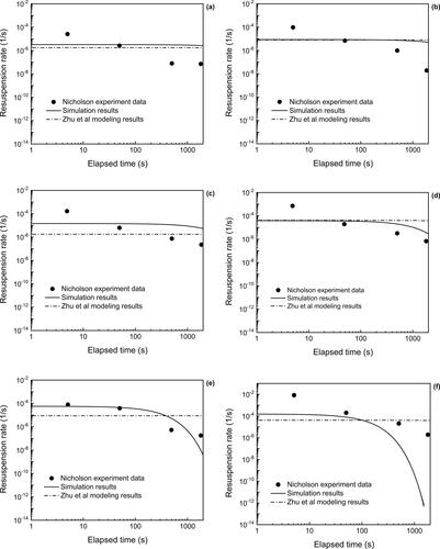
In this section, simulation results are first validated against experiment data, then the effects of some critical parameters including particle diameter, resuspension fraction under a single turbulent burst and mainstream velocity are presented. The experiment data for validation originally come from the researches of Nicholson (Nicholson Citation1993) and Giess (Giess, Goddard, and Shaw Citation1997).
3.1. Model validation
Validation results of the proposed model are given in and . As can be seen in , the accuracy of the proposed model increases with the increase of mainstream velocity from 3 m/s to 8 m/s for 4.1 μm particles. Take the data ranges for instance, the simulated particle resuspension rate for 3 m/s and 4.5 m/s maintains between 10−4 and 10−6, but the experimental data ranges from 10−3 to 10−8 as shown in and . The ranges of particle resuspension rate for 8 m/s are 10−4∼10−7 in simulation and 10−4∼10−8 in experiment. But in the case of 9.6 μm particles, simulation results under the velocity of 4.5 m/s reach a better agreement with the experiment data compared to other mainstream velocities. It is also evident that the time-resolved resuspension rate R gradually decreases with the increase of time, and this tendency changes rapidly under a higher mainstream velocity as depicted in and . Here is one possible explanation: as illustrated in EquationEquation (23)(23)
(23) , the probability of particle resuspension (by a single turbulent burst) is inversely proportional to time. Besides, the initial surface particle load is fixed thus the number of particles resuspended from the surface would gradually decrease over time. Base on the definition in EquationEquation (25)
(25)
(25) , the time-resolved resuspension rate R would also decrease over time. In addition, the present result is in accordance with validation data of the experiment conducted by Nicholson (Nicholson Citation1993) and other short-term particle resuspension outcomes (Reeks, Reed, and Hall Citation1988). Comparing the simulation results of the proposed model and the modeling results from Zhu’s study, similar predictions can be found in and , and the most significant discrepancies can be observed in and . As demonstrated in EquationEquation (16)
(16)
(16) , EquationEquation (17)
(17)
(17) and EquationEquation (23)
(23)
(23) , higher flow velocity corresponds to a higher chance of getting resuspended for fixed particle size and particle surface load. Thus, the decrease trends over time predicted by the proposed model of resuspension rates in and seem to be more reasonable. However, it is still hard to conclude that the proposed model can give a better prediction for any other complicated situations. Because (1) a revised modeling results for only 4.1 μm particles showing good agreement with experiment data have been further provided in Zhu’s research (Zhu et al. Citation2012). (2) both the proposed model and validation cases have been, to some extent, simplified in the present study.
Figure 5. Comparison of particle resuspension rate between simulation/modeling results and experimental data in validation Case 1 for 4.1 μm (left part) and 9.6 μm (right part) particles under various mainstream velocities (a) and (b) 3 m/s, (c) and (d) 4.5 m/s, and (e) and (f) 8 m/s.
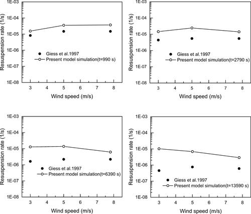
The real time for particle phase simulation of validation case 2 is 13590 s, then calculated resuspension rates at 990 s, 2790s, 6390s, and 13590 s are validated against experiment data (Giess, Goddard, and Shaw Citation1997), respectively. Corresponding results are given below in . As illustrated in , the simulated results agree well with experimental data for most of the time. Moderate discrepancies, however, can also be found at t = 6390s and t = 13590 s under low wind speed (s). Not considering particle deposition may be partially responsible for abovementioned differences. Since the overall predictive accuracy is reasonable, the simulated results indicate that the proposed new model has solid validity.
Figure 6. Comparison of particle resuspension rates between simulation results and experimental data in validation Case 2 for different wind speeds at 990 s, 2790 s, 6390 s, and 13590 s.
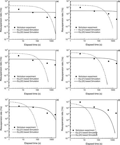
3.2. Effects of the choice of α expression
One of the key parameters α, as we mentioned above in the method part, is originally determined by EquationEquation (20)(20)
(20) . Another alternative is also given in EquationEquation (21)
(21)
(21) . Corresponding simulation results are presented below, as depicted in the results show some interesting features. For instance, EquationEquation (21)
(21)
(21) based simulation results have the largest average decrease rate compared to simulation results based on EquationEquation (20)
(20)
(20) . That is because the deposited particle load on surface is constant and a larger α means higher resuspension rate, after a specific time period, EquationEquation (21)
(21)
(21) based resuspension rate decreases rapidly due to constantly decreased remaining particles. To avoid showing extremely low values which might make other results indistinguishable and incomparable, it should be pointed out that not all the simulation results in are given from the initial time to 1800s. As demonstrated in EquationEquation (23)
(23)
(23) , the resuspension probability will decrease over time to a nearly constant low level. It is therefore reasonable to observe evident bent curves for larger α values. To achieve more accurate prediction results, as mainstream velocity increases, the expression of α should not be considered as constant and the value of α should also be increased accordingly from 10−4 to 10−2 (from the recommendation of Zhu to the recommendation of Cleaver and Yates). For most of the modeling cases depicted in , EquationEquation (20)
(20)
(20) based simulation results are better than that of EquationEquation (21)
(21)
(21) when validated against experiment data. As mentioned in the methods section, currently there are two main info sources to determining the parameter α: the assumption of EquationEquation (20)
(20)
(20) proposed by Zhu et al. (Citation2012), and the recommended expression of EquationEquation (21)
(21)
(21) proposed by Cleaver and Yates (Cleaver and Yates Citation1973). Results in indicate a better overall performance of EquationEquation (20)
(20)
(20) based model than that of EquationEquation (21)
(21)
(21) based model. In and , however, trends of resuspension rates can be better predicted by the EquationEquation (21)
(21)
(21) based model. The difference between and and and lies in the airflow velocity. It is reasonable to assume α as a function, which is not accurately built in neither Zhu’s (Zhu et al. Citation2012) nor Cleaver and Yates’ (Citation1973) research, of specific parameters including but not limited to airflow velocity with a more clear range. Therefore, more analytical as well as experimental investigations are needed. For the present study under current conditions, however, the expression of α in EquationEquation (20)
(20)
(20) is still acceptable.
Figure 7. Effects of resuspension fraction of a single turbulent burst on resuspension rate for 4.1 μm (left part) and 9.6 μm (right part) particles under various mainstream velocities (a) and (b) 3 m/s, (c) and (d) 4.5 m/s, and (e) and (f) 8 m/s.
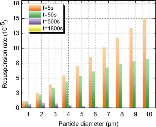
3.3. Effects of particle diameter
To investigate the effects of particle diameter on resuspension rate, particles with totally 10 different sizes are tested. And the diameters are 1, 2, 3, 4, 5, 6, 7, 8, 9 and 10 μm, respectively. Unlike other researches, the present study focused on transient characteristics and corresponding particle size effects of particle resuspension process. Thus particle resuspension rate at four time points mentioned in the work of Nicholson (Nicholson Citation1993), namely 5 s, 50 s, 500 s and 1800s, are compared. Corresponding results are given in and under the mainstream velocities of 4.5 m/s and 8 m/s, respectively. Since the simulation results under these two mainstream velocities have a better agreement with experiment data in and , these two mainstream velocities therefore are chosen for the next analysis. In general, the resuspension rate increases with the increase of particle diameter within the first 500 s for 4.5 m/s and 50 s for 8 m/s results. As depicted in , however, the resuspension rate at 1800s first increases to a peak value, which corresponds to the particle diameter between 4 μm and 5 μm, then decreases with the increase of particle diameter. Similar results can be found at 500 s in , but the critical particle diameter leading to the highest resuspension rate is approximately 2 μm. In particular, resuspension rate tends to remain a decreasing tendency at 1800s from the diameter of 1 μm to 10 μm, and it is easy to put an explanation on the results: As concluded in previous research, under a specified flow condition, particles with larger diameters are easier to resuspend from smooth surface (Mei, Zhang, and Wang Citation2016) or with higher resuspension rates (Zhu et al. Citation2012). Given a limited particle surface load, the resuspension rate decreases rapidly after sufficient particles are removed from particle laden substrate, which is also in accordance with the expression of EquationEquation (23)(23)
(23) . From another perspective, to obtain a constant resuspension rate in possible practical application, the size of particles should be limited (For instance, 1 μm particles under 4.5 m/s and submicron particles under 8 m/s).
Figure 8. Effects of particle size on resuspension rate under mainstream velocity of 4.5 m/s.
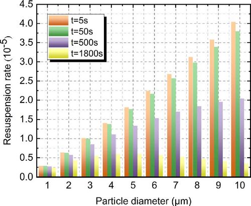
Figure 9. Effects of particle size on resuspension rate under mainstream velocity of 8 m/s.
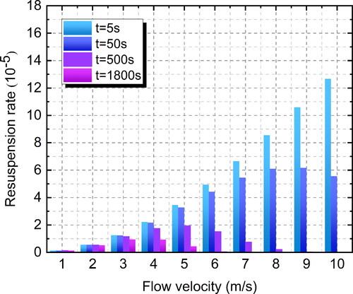
3.4. Effects of mainstream velocity
Mainstream velocity (or the main flow velocity of ventilation duct) of the studied case might be a crucial factor influencing the flow field characteristics, which include corresponding boundary layer thickness, turbulence intensity and velocity gradient distributions. To verify the sensitivity of resuspension rate to mainstream velocity, different mainstream velocities ranging from 1 m/s to 10 m/s are tested. In this section, transient characteristics and corresponding mainstream velocity effects on particle resuspension process are also our primary concerns. To be consistent with the results shown in and , particles with diameters of both 9.6 μm and 4.1 μm in the study of Nicholson (Nicholson Citation1993) are adopted for the present section. Simulated results are given in and , respectively.
Figure 10. Effects of mainstream velocity on resuspension rate of 9.6 μm particles.
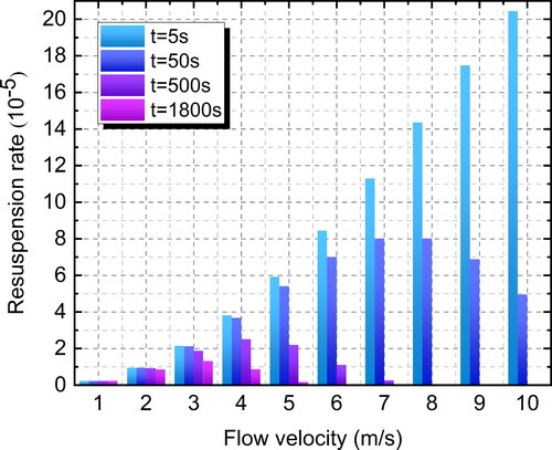
As depicted in , particle resuspension rate at 5 s increases with the increase of mainstream velocity. But the resuspension rate after 50 s first increases to a peak value then decreases as mainstream velocity increases. There might be several optimal mainstream velocities under which particles are much easier to get resuspended. For instance, the optimized mainstream velocities are 7 m/s, 4 m/s and 3 m/s at 50 s, 500 s, and 1800 s, respectively. Comparing the results in with the results in (or ), the proposed model seems to be more sensitive to the change of mainstream velocity instead of particle diameter for the present study. Similar results can be found for 4.1 μm particles as shown in , it is evident that the critical mainstream velocities for the highest particle resuspension rates are 9 m/s, 5 m/s and 3 m/s at 50 s, 500 s and 1800s, respectively. Regardless of the effect of particle size, the critical mainstream velocities for promoting particle resuspension still maintain a decreased tendency over time. The reason why the critical mainstream velocity can be observed is that higher flow velocity usually leads to higher particle resuspension rate as we analyzed in section 3.1 or the modeling results provided by previous literature (Zhu et al. Citation2012), meanwhile the total particle number remains constant and then the increasing rate of resuspended particles for higher flow velocity would be becoming larger than that for lower flow velocities over time. This also explains why the critical mainstream velocity changes from higher flow velocities to lower ones over time. Similar to the effects of particle size, in order to obtain a relatively constant resuspension rate for possible practical application over time, a smaller mainstream velocity should be considered. More specifically in the studied cases in and , the maximum mainstream velocity is approximately 2 m/s for both 9.6 μm and 4.1 μm particles.
Figure 11. Effects of mainstream velocity on resuspension rates of 4.1 μm particles.
It is worth noting that in the experimental research conducted by Nicholson (Nicholson Citation1993), only 3 m/s, 4.5 m/s, 8 m/s are tested to evaluate the dependence of resuspension on wind speed, which contains averaged resuspension rates over each entire experiment. Meanwhile, only the diameters of 4.1 μm, 9.6 μm, 17.5 μm (not used in our study due to significant gravitational settling) and 22.1 μm (not used in our study due to the same reason) are tested to evaluate the dependence of resuspension on particle diameter, which contains averaged resuspension rates over each entire experiment as well. The time-resolved resuspension rates of specific conditions (3 m/s, 4.5 m/s, 8 m/s and 4.1 μm, 9.6 μm) have already been validated in section 3.1., therefore, no more validation data from Nicholson’s research can be used to verify simulation results in section 3.3 and 3.4. The validity of the proposed model, however, have been fully proved in section 3.1 to ensure the correctness of the results in section 3.3 and 3.4.
4. Discussion
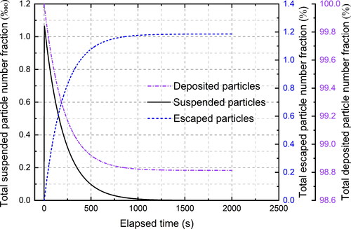
The discussion section is primarily based on the simulation results of validation Case 1. The evolutionary curves of overall deposited, resuspended, escaped 4.1 μm particle fractions under the velocity of 8 m/s are depicted in . All deposited particles are summarized from subspaces numbered from n + 1 to nadd, resuspended particles are collected from subspaces numbered from 1 to n, and escaped particles are collected from subspace n+nadd+1. As can be seen in , final escaped particle fraction is around 1.2% and final deposited particle fraction remains about 98.8%. The highest resuspended particle fraction reaches approximately 1.07 ‱ almost at the very beginning, which is quite small compared with the number of initially deposited particles. This is because under current flow conditions the turbulent burst frequency is proportional to mainstream velocity, and according to the study conducted by Boor (Boor, Siegel, and Novoselac Citation2013), only about 5% (2.4%) deposited 10 μm (3 μm) particles can be observed to get resuspended under 25 m/s for 100 s wind tunnel exposure with RH = 30%. As can be seen for the present case, after 500 s, changing rates of all three types of particles begin to slow down and gradually approaches a constant value for elapsed times larger than 1000 s. Similarities of evolutionary curves can be found in other cases with different simulation conditions.
Figure 12. Evolution of overall deposited, resuspended, escaped 4.1 μm particle fractions under the velocity of 8 m/s.
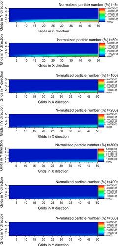
To have a direct view of distribution of the resuspended particles within the computational domain and its dynamic process. Particle distributions at 5 s, 50 s, 100 s, 200 s, 300 s, 400 s, and 500 s within the y = 0.5 m central penal are presented in , where x/y axis represents cell number sequence and resuspended particle numbers are normalized by the number of initially deposited particles. As mentioned before, the grid resolution used in particle phase simulation after the grid-merging operation is 50 × 5 × 5 (x × y × z), so the subspace (or grid) layers range from z = 1 to z = 5 along z + direction. After examining the simulation results in , only grids on layer z = 1 and layer z = 2 contain resuspended particles under current flow condition. As also can be seen in , particle number concentration may increase along duct length due to convective flow transfer. Most of the resuspended particles fall into the layer z = 1 for 4.1 μm particles, that is because for the present unidirectional flow the convective flow velocity in the z + direction is ignorable compared with the mainstream flow velocity in the x+ direction. Another phenomenon which should be pointed out is that after 500 s, the resuspension rate as well as the resuspended particle concentrations in all cells of each layer are less significant. This also can be verified by the data of 4 μm particles in . It is obvious that the proposed model can provide a total solution on both particle resuspension process and particle transmission/distribution predictions. And it also can help us understand what happens between microscale turbulent induced resuspension and macroscale airborne particle movement simultaneously.
Figure 13. Resuspended 4.1 μm particle numbers in cells of y = 0.5 central panel under mainstream velocity of 8 m/s from 5 s to 500 s.
Even though the Markov chain based model, as proved in previous researches, consumes much less time compared with conventional Lagrangian model and Eulerian model (Chen et al. Citation2015; Mei et al. Citation2017), there still exist some limitations. For instance, the proposed model takes less than 850 s time for particle phase simulation. More specifically, the data preparing process costs less than 20 s, the construction of the original State Transfer Matrix P takes 76 s, the turbulent burst theory based modification of the State Transfer Matrix P and state transfer simulation costs about 747 s (less than 13 min). But as investigated in previous study (Mei and Gong Citation2018), the gravity based modification of the State Transfer Matrix P requires much less time. In that study (Mei and Gong Citation2018), gravity based modification mainly differs from turbulent burst theory based modification in the probabilistic expressions. The exact time consumptions for different parts of the simulation process could be case-dependent but usually associated with ultimate grid resolutions and probabilistic expressions. Comparing the computational costs of the present study and other researches could reveal the efficiency advantage of the proposed model. The simulation case (only considering particle passive transfer) investigated by Chen et al (Chen, Yu, and Lai Citation2006) using a set of grid with the resolution of 40 × 20 × 20, and it takes 30 min to finish particle phase simulation by CFD Eulerian approach. The grid resolution of present case (for airflow simulation) is 250 × 20 × 20, it is reasonable to estimate a computing time longer than 30 min with Eulerian model under the present grid resolution. Besides, flow field simulation consumes a large proportion of computing time. To further reduce the computational cost, Fast Fluid Dynamics (FFD) and/or online-offline databases would be better choices for real-time (or even faster-than-real-time) acquisition of flow field information, which is crucial for real-time construction of the State Transition Matrix P. Furthermore, if only overall parameters such as resuspension counts/rates of the whole chamber are needed, the so-called grid-merging operation can be used to further reduce grid resolution, which indicates that the proposed model is more computationally efficient compared with CFD Eulerian model and has the potential for fast (or even real-time) prediction of particle phase simulation. Thus the proposed model can probably be applied to: (1) provide real-time or even faster-than-real-time information on resuspension and distribution of deposited poisonous or hazardous particle under emergency situations including terrorist attack with biological weapon, hazardous dust leakage and conflagration. (2) evaluate efficiencies of specific methods in removing particles from silicon wafer, and help to promote production efficiency in semiconductor industries. (3) numerically investigate the detachment process of droplets from human respiratory tracks with complicated bronchial trees, and efficiently reveal the mechanism of human exhalation activities.
The present article aims to explore and provide an alternative choice, which is a new and computationally efficient model, to numerically predict the particle resuspension process instead of directly considering micro-actions of deposited particles during the resuspension process. The authors believe that the proposed model can be used to help to understand the particle resuspension process better in many other scenarios, which is not further investigated here due to page limitation. Meanwhile, it is also worth mentioning again that the present model fails to take gravity induced particle deposition into account, which may slightly reduce the accuracy of the simulation results if significant deposition behaviors can be observed. However, further improvement for the proposed model should and can be made in the near future.
5. Conclusion
In this article, a probabilistic model based on Markov chain and turbulent burst theory for predicting particle resuspension is proposed. Compared with conventional Lagrangian and Eulerian methods, the proposed model is developed to solve particle resuspension problems with desirable resolutions of particle concentration and less computational consumption. Based on the presented results, the following conclusions can be drawn:
First, the proposed model is validated against experiment data and proved to be able to simulate deposited particle resuspension under turbulent flow. The accuracy and the applicability of the proposed model is found to be affected by the choice of α expression, which represents the fraction of particles resuspended by a single turbulent burst. The determination of α is recommended by considering flow characteristics instead of treating it as constant when applying the proposed model under relatively wide ranges of flow velocities (i.e. increasing the value of α with the increase of the mainstream velocity). Second, particles with larger diameters or under higher mainstream velocity are easier to get resuspended from surfaces. And the discrepancies of time-resolved resuspension rate become less significant as particle size or mainstream velocity decreases, which means the resuspension rate is approximately close to constant over time. Third, the computational cost of the proposed model varies with grid resolutions (usually based on users’ demands) and resuspension probability expressions. Nevertheless, the overall computing time of the proposed model is still less than that of traditional CFD models. The proposed model provides a completely new alternative choice to numerically and efficiently predict resuspension and dispersion of particulate (gaseous) contaminants in indoor/enclosed environment.
Acknowledgments
The investigation was supported by the National Science & Technology Supporting Program through grant No. 2015BAJ03B00, the National Natural Science Foundation of China through grant No. 51808555, the Natural Science Foundation of Hunan Province (Youth Program) through granted No. 2021JJ40591, the Doctoral Scientific Research Foundation of Changsha University of Science and Technology through granted No. 097/000301518 and the Scientific Research Project of Hunan Provincial Department of Education through granted No. 20C0033.
References
- And, E. Y., P. K. Hopke, and L. Wallace. 1999. Receptor modeling assessment of particle total exposure assessment methodology data. Environ. Sci. Technol. 33 (20):3645–52. doi: 10.1021/es981122i.
- Arlian, L. G., J. S. Neal, M. S. Morgan, C. M. Rapp, and A. L. Clobes. 2001. Distribution and removal of cat, dog and mite allergens on smooth surfaces in homes with and without pets. Ann. Allergy. Asthma Immunol. 87 (4):296–302. doi: 10.1016/S1081-1206(10)62243-0.
- Boor, B. E., J. A. Siegel, and A. Novoselac. 2013. Wind tunnel study on aerodynamic particle resuspension from monolayer and multilayer deposits on linoleum flooring and galvanized sheet metal. Aerosol Sci. Technol 47 (8):848–57. doi: 10.1080/02786826.2013.794929.
- Chen, C.,. C. H. Lin, Z. Long, and Q. Chen. 2014. Predicting transient particle transport in enclosed environments with the combined computational fluid dynamics and Markov chain method. Indoor Air. 24 (1):81–92. doi: 10.1111/ina.12056.
- Chen, C.,. W. Liu, C.-H. Lin, and Q. Chen. 2015. A Markov chain model for predicting transient particle transport in enclosed environments. Build. Environ. 90:30–6. doi: 10.1016/j.buildenv.2015.03.024.
- Chen, F., S. C. M. Yu, and A. C. K. Lai. 2006. Modeling particle distribution and deposition in indoor environments with a new drift–flux model. Atmos. Environ 40 (2):357–67. doi: 10.1016/j.atmosenv.2005.09.044.
- Cleaver, J., and B. Yates. 1973. Mechanism of detachment of colloidal particles from a flat substrate in a turbulent flow. J. Colloid Interface Sci. 44 (3):464–74. doi: 10.1016/0021-9797(73)90323-8.
- Ferro, A. R., R. J. Kopperud, and L. M. Hildemann. 2004. Source strengths for indoor human activities that resuspend particulate matter. Environ. Sci. Technol. 38 (6):1759–64. doi: 10.1021/es0263893.
- Giess, P., A. Goddard, and G. Shaw. 1997. Factors affecting particle resuspension from grass swards. J. Aerosol Sci. 28 (7):1331–49. doi: 10.1016/S0021-8502(97)00021-9.
- Goldasteh, I., G. Ahmadi, and A. R. Ferro. 2013. Monte Carlo simulation of micron size spherical particle removal and resuspension from substrate under fluid flows. J. Aerosol Sci. 66:62–71. doi: 10.1016/j.jaerosci.2013.07.012.
- Gomes, C., J. Freihaut, and W. Bahnfleth. 2007. Resuspension of allergen-containing particles under mechanical and aerodynamic disturbances from human walking. Atmos. Environ. 41 (25):5257–70. doi: 10.1016/j.atmosenv.2006.07.061.
- Habchi, C., K. Ghali, and N. Ghaddar. 2016. Coupling CFD and analytical modeling for investigation of monolayer particle resuspension by transient flows. Build Environ 105:1–12. doi: 10.1016/j.buildenv.2016.05.025.
- Henry, C., and J. P. Minier. 2014. A stochastic approach for the simulation of particle resuspension from rough substrates: Model and numerical implementation. J. Aerosol Sci. 77:168–92. doi: 10.1016/j.jaerosci.2014.08.005.
- Krauter, P., and A. Biermann. 2007. Reaerosolization of fluidized spores in ventilation systems. Appl. Environ. Microbiol. 73 (7):2165–72. doi: 10.1128/AEM.02289-06.
- Liu, Z., S. Ma, G. Cao, C. Meng, and B.-J. He. 2018. Distribution characteristics, growth, reproduction and transmission modes and control strategies for microbial contamination in HVAC systems: A literature review. Energy Buildings 177:77–95. doi: 10.1016/j.enbuild.2018.07.050.
- Liu, W., R. You, and C. Chen. 2019. Modeling transient particle transport by fast fluid dynamics with the Markov chain method. Build. Simul. 12 (5):881–9. doi: 10.1007/s12273-019-0513-9.
- Mei, X., and G. Gong. 2018. Predicting airborne particle deposition by a modified Markov chain model for fast estimation of potential contaminant spread. Atmos. Environ. 185:137–46. doi: 10.1016/j.atmosenv.2018.04.050.
- Mei, X., G. Gong, H. Su, P. Peng, J. Liu, and H. Xie. 2017. A grid-merging operation to accelerate the Markov chain model in predicting steady-state and transient transmission of airborne particles. Build Environ. 122:82–93. doi: 10.1016/j.buildenv.2017.05.038.
- Mei, X., T. Zhang, and S. Wang. 2016. Experimental investigation of jet-induced resuspension of indoor deposited particles. Aerosol Sci. Technol. 50 (3):230–41. doi: 10.1080/02786826.2016.1143084.
- Mortazavi, R. 2005. Reentrainment of submicron solid particles. Ph.D. Thesis., Virginia Commonwealth University, Richmond, VA, USA.
- Nicas, M. 2000. Markov modeling of contaminant concentrations in indoor air. AIHAJ 61 (4):484–91. doi: 10.1080/15298660008984559.
- Nicholson, K. 1993. Wind tunnel experiments on the resuspension of particulate material. Atmos. Environ. Part A 27 (2):181–8. doi: 10.1016/0960-1686(93)90349-4.
- Qian, J., J. Peccia, and A. R. Ferro. 2014. Walking-induced particle resuspension in indoor environments. Atmos. Environ. 89:464–81. doi: 10.1016/j.atmosenv.2014.02.035.
- Reeks, M. W., and D. Hall. 2001. Kinetic models for particle resuspension in turbulent flows: theory and measurement. J. Aerosol Sci. 32 (1):1–31. doi: 10.1016/S0021-8502(00)00063-X.
- Reeks, M. W., J. Reed, and D. Hall. 1988. On the resuspension of small particles by a turbulent flow. J. Phys. D: Appl. Phys. 21 (4):574–89. doi: 10.1016/0021-8502(95)97197-M.
- Theerachaisupakij, W., S. Matsusaka, Y. Akashi, and H. Masuda. 2003. Reentrainment of deposited particles by drag and aerosol collision. J. Aerosol Sci. 34 (3):261–74. doi: 10.1016/S0021-8502(02)00180-5.
- White, F. M. 1986. Fluid Mechanics. New York: McGraw-Hill.
- Wu, T., M. Täubel, R. Holopainen, A.-K. Viitanen, S. Vainiotalo, T. Tuomi, J. Keskinen, A. Hyvärinen, K. Hämeri, S. E. Saari, et al. 2018. Infant and Adult Inhalation Exposure to Resuspended Biological Particulate Matter. Environ. Sci. Technol. 52 (1):237–47. doi: 10.1021/acs.est.7b04183.
- Zhang, T., P. Li, Y. Zhao, and S. Wang. 2013. Various air distribution modes on commercial airplanes-part 2: computational fluid dynamics modeling and validation. HVACR Res. 19 (5):457–70. doi: 10.1080/10789669.2013.789368.
- Zhang, Z.,. W. Zhang, Z. Zhai, and Q. Chen. 2007. Evaluation of various turbulence models in predicting airflow and turbulence in enclosed environments by CFD: Part 2-Comparison with experimental data from literature. HVAC&R Res. 13 (6):871–86. doi: 10.1080/10789669.2007.10391460.
- Zhu, Y., B. Zhao, B. Zhou, and Z. Tan. 2012. A particle resuspension model in ventilation ducts. Aerosol Sci. Technol. 46 (2):222–35. doi: 10.1080/02786826.2011.618471.
- Ziskind, G., M. Fichman, and C. Gutfinger. 1995. Resuspension of particulates from surfaces to turbulent flows—Review and analysis. J. Aerosol Sci. 26 (4):613–44. doi: 10.1016/0021-8502(94)00139-P.
- Zuo, B., K. Zhong, and Y. Kang. 2015. An experimental study on particle resuspension in a room with impinging jet ventilation. Build Environ. 89:48–58. doi: 10.1016/j.buildenv.2015.01.031.