
Abstract
Pressurized metered dose inhalers (pMDI) are one of the most common devices to deliver therapeutic treatment to patients with asthma or COPD. The atomization mechanism responsible for droplet production is poorly understood because of the short length and timescales involved, making experimental investigations to characterize fluid flow structures and spray formation processes difficult. This article reports the findings of new high-speed and high-resolution imaging and temperature measurements seeking to improve the fundamental understanding of the atomization mechanism of the pMDI. An annular flow regime of gaseous core in liquid annulus was observed in the orifice. Shock diamonds within the flow, viewed via Schlieren imaging, confirmed experimentally for the first time the choked nature of the orifice exit flow. Propellant formulation flow in the orifice was found to be superheated to a degree that significant flashing and evaporation at the orifice exit is likely to take place. This information points to a hybrid mechanism of predominantly aerodynamic atomization with significant liquid flashing upon exit from the orifice producing a near instantaneous formation of respirable droplets. Large irrespirable droplets are produced by two mechanisms; breakup of liquid slugs ejected from the orifice, due to unsteady transient fluid structures in the actuator sump and stripping of ligaments from a liquid pool around the orifice exit, which subsequently break up into large droplets in the periphery of the plume. This new understanding will aid development of next generation, high efficiency pMDIs, particularly those employing low global warming potential propellants such as HFA152a or HFO1234ze(E).
Copyright © 2022 American Association for Aerosol Research
EDITOR:
Introduction
Pressurized metered dose inhalers (pMDIs) are self-contained drug delivery devices for controlling symptoms of asthma and COPD (Stein and Thiel Citation2017). In Europe, 48% of inhaled medications sold between 2002 and 2008 were pMDIs (Myrdal, Sheth, and Stein Citation2014) and a recent estimation suggests that 262 million people suffer from asthma worldwide (World Health Organisation Citation2021). Drug particles with mass median aerodynamic diameter in the range of 0.5 to 5 µm are required for lung deposition (Stahlhofen, Rudolf, and James Citation1989) and effective bronchodilator treatment (Shekunov et al. Citation2007; Ivey, Vehring, and Finlay Citation2015). These are produced in large quantities by pMDIs, but a substantial proportion of the drug dose is known to deposit in the oral cavity. This reduces drug delivery efficiency and therapeutic effectiveness (Everard Citation2000; Newman Citation2005) and can result in side effects, such as oral candidiasis, dysphonia, bronchospasm, and systemic exposure (Yarbrough, Mansfield, and Ting Citation1985). Poor patient coordination with the pMDI device is partly responsible for oropharyngeal drug deposition, but other leading causes are the presence of very large non-respirable droplets in pMDI aerosols, as well as high spray plume velocities leading to inertial impaction and turbulent diffusion (Stein and Gabrio Citation2000; Lewis Citation2007). Little is known about the factors that are responsible for these aerosol characteristics.
Early studies by Fletcher (Citation1975), Clark (Citation1991) and Dunbar (Citation1996) focused on atomization of pure propellant. Fletcher analyzed production of CFC propellant aerosol in steady state conditions flowing through a transparent model twin-orifice actuator. Clark (Citation1991) extended Fletcher’s work to metered flows of CFCs and HFAs and proposed a mechanism of droplet production by pMDIs in terms of the following processes: (i) flash boiling in the metering chamber creating dispersed vapor bubbles in liquid propellant, followed by (ii) the formation of liquid filaments surrounded by propellant vapor in the expansion chamber, and (iii) atomization in the spray orifice. Dunbar (Citation1996) studied flows of HFA134a and CFC placebos as well as a suspension formulation containing salbutamol. He found that choked two-phase flow in the pMDI spray orifice produced a highly dynamic spray consisting of an unsteady, transient, three-dimensional, two-phase mixture of droplets in vapor with high turbulence levels.
High-speed flow visualizations inside a transparent pMDI model by Versteeg, Hargrave, and Kirby (Citation2006) and Versteeg and Hargrave (Citation2006) showed that the liquid was in fact the continuous phase in the expansion chamber surrounding dispersed vapor. Details of the flow structures within the spray orifice could not be observed in detail, but it was conjectured that the flow regime comprised of an annular liquid film on the orifice walls and that the primary atomization mechanism resembled air-blast atomization (Lefebvre and McDowell Citation2017). Extremely large droplets were identified with size up to 100 µm produced by ligament stripping from a liquid pool around the orifice exit toward the end of the spray event.
Modern HFA-based pMDI solution formulations contain excipients such as ethanol, glycerol or polyethylene glycol. These compounds modulate pMDI atomization in order to provide a close match to the aerosol characteristics of CFC pMDIs (Brambilla et al. Citation1999; Ganderton et al. Citation2002), which were phased out following ratification of the 1987 Montreal Protocol. Myatt, et al. (Citation2015a, Citation2015b) imaged atomization of mixtures of HFA134a and ethanol in a transparent model pMDI. Addition of small amounts of ethanol resulted in a bubbly flow structure in the actuator sump and a more stable spray plume. Mason-Smith et al. (Citation2015) captured the aerosol plume of formulations of HFA134a and HFA227ea with and without 15% ethanol cosolvent. Mason-Smith et al. (Citation2017) undertook x-ray phase contrast imaging of flows of these fluids inside a commercial actuator. These studies showed that pure HFA134a flows produced a large vapor core through the center of the valve stem into the sump, with liquid surrounding the vapor. HFA134a with 15% ethanol exhibited a bubbly flow structure through the valve stem and into the sump, confirming that earlier findings of studies with transparent models provide useful models of flows in commercial actuators.
Due to limited spatial or temporal experimental resolution, the flow structure in the spray orifice - arguably the most important region from the perspective of atomization - is at present poorly understood. Moreover, the connection between the flow regimes in the actuator sump and droplet production is uncertain. This article reports the findings of optical diagnostic investigations of the flow inside the spray orifice, the flow regime at the orifice inlet and spray near the orifice exit of transparent actuator models. The internal and external flow processes were investigated using high-speed flow visualizations to study liquid and vapor flows in detail. Fine wire thermocouples were also used to capture the temperature and therefore level of superheat of the fluid within the spray orifice with the overall aim of improving the fundamental understanding of the atomization mechanism of the pMDI.
Materials and methods
Aerosols used in this research were manufactured using 19 ml C128 cut edge canisters, (Presspart Manufacturing Ltd, Blackburn, UK) crimped with BK357 50 µl metering valves (Bespak Europe Ltd, Kings Lynn, UK). Cans were filled with ethanol (Sigma Aldrich Co Ltd, Irvine, UK) prior to crimping and pressure filling with HFA134a propellant (Mexichem UK Limited, Runcorn, UK) using a Pamasol laboratory filling plant P2016 (Pamasol Willi Maden AG, Pfaffikon, SZ).
Aerosols were actuated through Bespak 630 series actuators (Bespak Europe Ltd, Kings Lynn, UK) or custom transparent actuator models using bespoke test rigs utilizing a Nanotec L4118S1404-T5X5-A25 linear actuator with SMCI12 controller (Nanotec Electronic GmbH & Co., Feldkirchen/Munich, Germany) for repeatable actuation and programmable acceleration, speed, and distance. Aerosols were depressed 2 mm from an actuator contacting position with a hold time of one second and a depression and release ramp of 0.2 s.
Transparent models with equivalent sump volume and orifice diameter as the Bespak 630 series test actuator were manufactured from PETg (Bayer Sheet Europe GmbH, Darmstadt, Germany) and polished to enable visualization of internal fluid flow structures.
Internal and external flow imaging
High resolution images of the internal flow and aerosol spray plume were captured using a Canon EOS 5DSR (Canon Inc., Tokyo, Japan) 50 megapixel DSLR camera coupled by extension rings to a 12X zoom lens with (Navitar, Inc., New York, USA) or a AF Micro-Nikkor 200 mm f/4D IF-ED macro lens (Nikon, Tokyo, Japan), in some cases also with a 2x teleconverter (Vivitar Corporation, Edison, NJ, USA). Back illumination was provided by a cell of Fluorescein 27 dye (Photonic Solutions Ltd, Edinburgh, UK) solution pumped by a Surelite SL II-10 SSP Nd:YAG laser (Continuum, San Jose, CA, USA).
Schlieren imaging
A pair of 1,000 mm focal length lenses were placed either side of the spray plume to provide collimated illumination. A 3 W LED point light source driven by a 330 mA step down DC driver (Sure Electronics Co., Ltd, Nanjing, China), was placed at the focal point of the first lens. A vertical knife edge was placed 1,000 mm from the second lens to block roughly half of the light passing to a LaVision Imager pro HS 4 M camera, equipped with a Vivitar 2x teleconverter and Nikon Micro-Nikkor 200 mm macro lens. A laser sheet, used to simultaneously visualize droplets in the spray was produced by a Litron LDY304 Nd:YLF double-pulsed laser (Litron, Rugby, UK) coupled with a series of cylindrical and spherical lenses and a slit aperture.
Temperature measurement
A fine wire type-K thermocouple of CHROMEGA® and ALOMEGA® wires (OMEGA Engineering, Manchester, UK), 25 µm nominal diameter, was embedded within the spray orifice of a transparent model allowing measurement of the vapor-liquid fluid temperature. The thermocouple signal was amplified using an Analog Devices AD595C (Analog Devices, Inc., Norwood, MA, USA) integrated circuit and recorded using a PicoLog 1216, 12-bit, 16 channel, high-speed data acquisition device (Pico Technology Limited, Saint Neots, UK) connected via USB to a laptop running PicoScope 6.11.12 software.
Results and discussion
Internal and external flow visualizations
Images showing the nature of the flow entering, within, and exiting the spray orifice and the near orifice spray are presented in . Large format orifice exit flow images may be found in supplemental Figures S4–S11.
Figure 1. Early actuation spray orifice annular flow regime; HFA134a at 2.5 ms, 5.0 ms, 7.5 ms, and 10.0 ms.
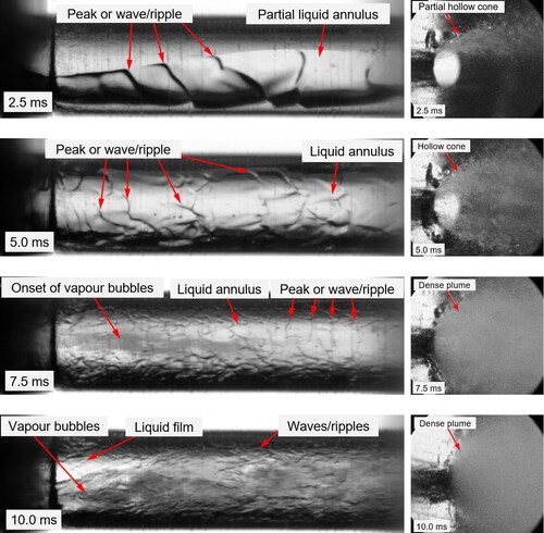
Figure 2. Dye cell illuminated spray orifice images of HFA134a at 50 ms (top), 100 ms (top-middle), 150 ms (bottom-middle), and 200 ms (bottom).
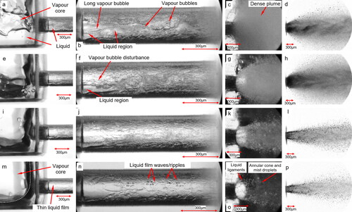
Figure 3. Dye cell illuminated spray orifice images of HFA134a/10% w/w ethanol at 50 ms (top), 100 ms (top-middle), 150 ms (bottom-middle), and 200 ms (bottom).
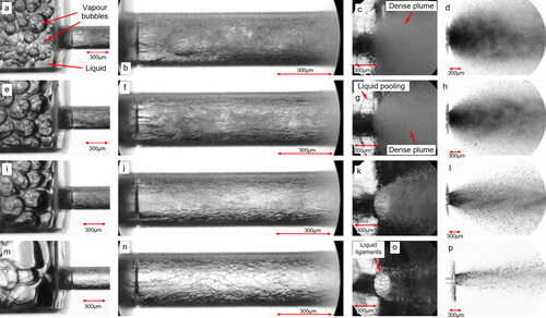
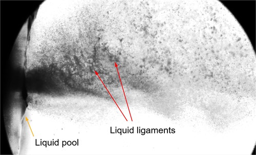
Figure 4. High resolution image of liquid slug ejection from Bespak actuator; HFA134a 50 ms.
A series of images of the orifice internal flow and near-field spray structure during the first 10 ms of a HFA134a spray are presented in . The build-up of flow comprises a thin annular film in the orifice with waves on the surface of the liquid indicating a slip velocity between the liquid and vapor core. This flow regime correlates with a peak of actuator sump pressure, wide near-orifice and far field spray cone angles (Myatt Citation2017), small initial droplet size and high spray exit velocity of previous measurements (Myatt, Stein, and Gavtash Citation2021, Myatt, et al. Citation2015a, Myatt, et al. Citation2015b).
at 50 ms, shows the flow structure of HFA134a leading to simultaneous delivery of vapor and liquid to the orifice. The vapor core in the sump is drawn into the orifice with varying quantities of liquid from the stratified liquid layer accumulated at the bottom of the sump. Vapor bubbles are seen in the liquid near the orifice wall in , and 3b. Similarly, liquid rich formulation flowing into the orifice from accumulated liquid at the bottom of the sump was also observed, as seen in .
The shearing action of the high velocity gas core on the surface of the liquid annulus causes mixing and disturbances within the liquid leading to a reduction in size of the liquid and vapor elements. Reducing length scales through the orifice leads to a large number of vapor-liquid interfaces which scatter/obscure the back-illumination, causing the right side of the orifice images in (e.g., ) to appear darker than the left side.
The spray at 50 ms is very wide and dense consisting of a very high number of small droplets at the core with a small number of large droplets at the periphery. The large near orifice cone angle is likely to contribute to increased pMDI actuator or oropharyngeal deposition, reducing the lung dose to the patient. No liquid film or ligaments are seen in the plume between one and two orifice diameters from the orifice exit, indicating that small droplets are produced just before, at, or just after the orifice exit. Observations in line with Park and Lee (Citation1994) confirm an annular flow regime likely dominates in the orifice. The decrease in vapor fraction (fluid quality) and reduction of the fluid pressure just after its peak in the actuator sump (Myatt, Stein, and Gavtash Citation2021), leads to the reduction in the near orifice and far field spray cone angles (Myatt Citation2017), a reduced spray exit velocity and an increased droplet size according to previous measurements (Myatt et al. Citation2015a, Citation2015b).
Between 100 ms and 150 ms, liquid at the bottom of the sump evaporates or is ejected increasing the sump fluid quality, so the internal vapor core grows, leading to predominantly vapor flow in the orifice. The thickness of the liquid annulus and density of the plume start to decrease such that the illumination directed through the orifice can be seen in orifice outflow images and the images of the orifice internal flow are brighter; this indicates fewer light scattering surfaces on or within the liquid annulus. At this late stage of the event the formulation pressure in the sump is significantly reduced, correlating with further reduced spray cone angle (Myatt Citation2017). However, the increased vapor fraction causes an increase in the spray exit velocity as the amount of gas to act on and accelerate the liquid is proportionally greater. The resultant increase in aerodynamic shearing action leads to a reduction of mean droplet size toward the end of the spray (Myatt, et al. Citation2015a, Citation2015b), although the mass fraction of emitted droplets is much lower at this time (Gavtash Citation2016a).
From 150 ms the spray cone angle and concentration of droplets reduce significantly. At this time, the vapor pressure and temperature of the formulation in the actuator sump have significantly reduced due to evaporative self-cooling (Myatt, Stein, and Gavtash Citation2021) resulting in poor atomization efficiency of the fluid. Liquid ligaments and large droplets of size order 50 µm are seen in the periphery of the plume, produced by shear stripping of the high velocity spray from a pool of cool liquid formulation surrounding the orifice exit, as also observed by Versteeg and Hargrave (Citation2006). Waves are seen on the thin liquid film surface indicating that the velocity of the vapor core is higher than that of the liquid film annulus. The length scale of ripples is typically multiple tens to one hundred microns in size (see ). From 200 ms large liquid ligaments are emitted which break up over an approximate axial distance of four or five orifice diameters forming large droplets (size > 50 µm), concentrated mainly in a hollow cone at the outer edge of the plume. These would likely impinge on the pMDI mouthpiece or in the mouth/throat region of the patient reducing the therapeutic dose delivered to the lungs.
Occasionally vapor flow into the orifice was cut off due to the dynamic and erratic nature of the sump fluid flow leading to periodic slugs of liquid rich formulation flowing into the orifice. The spray captured just after liquid slug ejection is shown in , showing similar liquid ligament structures and large droplets observed by Mason-Smith et al. (Citation2017) and Park and Lee (Citation1994) for bubbly or liquid slug/plug flow. These structures were observed exclusively for HFA134a, correlating with the erratic nature of the sump flow structure of this pure propellant as observed in our previous work (Myatt et al. Citation2015b) as well as by Mason-Smith et al. (Citation2017). Such liquid ligaments and droplets ejected are sufficiently large that they would be irrespirable and lead to oropharyngeal deposition. Recirculation zones in the orifice flow, suggested by Dunbar (Citation1996) as the source of bubble growth in the device and pulsations in the plume, were not observed in this work.
In the case of the HFA134a/10% w/w ethanol formulation, shown in , a bubbly flow in the actuator sump dominates which likely occurs due to the increase in surface tension of the formulation due to the presence of ethanol. The spray orifice is fed with a constant stream of bubbles throughout the spray event and distinct liquid-rich regions within the orifice are far fewer, or smaller, compared to pure HFA134a. Phase Doppler measurements of droplet size have indicated a reduction in the variability and erratic nature of the spray of ethanol-containing formulations, particularly in respect of large irrespirable droplet production (Myatt et al. Citation2015a, Citation2015b). Vapor bubbles drawn into the orifice can be seen but are generally broken up within the length of one orifice diameter. Further through the orifice it becomes harder to identify individual bubbles.
A similar effect on sump flow structure may also be seen with other formulation excipients due to changes in physical properties of the resulting formulation (e.g., surface tension, viscosity). The magnitude of the effect would depend upon the physical properties and the concentration of the excipient employed. Further work would be required to determine the extent of the effect in specific cases.
Schlieren imaging
shows a Schlieren image of the near orifice HFA134a spray emitted from a Bespak 630 series actuator. Shock diamonds were observed during early vapor emission. The onset of liquid droplet emission obscured shock diamonds during the main spray due to the high density of droplets near to the orifice exit. However, shock diamonds were seen when the near orifice was visible due to periodic reductions of near orifice plume density, particularly toward the end of the event suggesting their presence throughout the event, albeit obscured by the spray (see Figure S12 in supplemental information). Image analysis yielded shock cell lengths of around 0.4 mm, depending on formulation composition and elapsed time after actuation, enabling pressure ratio estimation as per relations developed by Love et al. (Citation1956). The pressure ratios determined agree well with theoretical analysis of choked pressure ratios for the same formulations (Gavtash Citation2016a). Moreover, previous measurements of formulation pressure in the actuator sump by (Myatt, Stein, and Gavtash Citation2021) reveal pressures well above that required for critical flow based on the shock cell length estimation and theoretical pressure ratio predictions, providing further evidence of choked flow throughout the event. Shock diamonds confirm experimentally for the first time the choked nature of pMDI spray orifice flow and therefore that vapor exits at sonic velocity.
Figure 5. Shock diamonds observed in Schlieren imaging; HFA134a 0 ms.
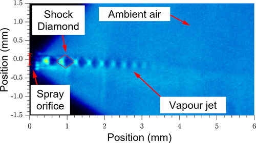
The gas phase velocity traveling through a shock is subject to the acceleration and deceleration effects of the pressure changes within the shock. Viscous losses and turbulent mixing with surrounding air cause the shocks to cease around 3 mm from the nozzle exit (). The sonic gas velocity of HFA134a at saturated ambient conditions is 146 m.s−1 (Huber and McLinden Citation1992) but it is well known that the sonic velocity of a two-phase mixture is significantly less than that of the single gas phase (Brennen Citation2005) due to the momentum transfer from the sonic gas to the liquid phase required to accelerate the liquid flow. Wall friction effects on the annular liquid flow highlighted in and reduce the liquid velocity as it exits the orifice compared to the sonic vapor phase giving rise to the ripples/waves seen in internal flow images.
Fluid temperature in the spray orifice
Temperature in the expansion chamber and actuator sump is highly variable during the spray event (). Immediately after the onset of flow, propellant expands and cold vapor flows into the spray orifice causing a sharp temperature drop. As warmer liquid fills the sump and flows through the orifice the temperature rises, peaking around 50 ms. This correlates with the time of lowest fluid quality in the expansion chamber before further liquid evaporation causes a monotonic temperature reduction. Upon exit to atmospheric conditions the two-phase fluid is in a superheated state (i.e., its temperature is higher than the saturation temperature of propellant at atmospheric pressure). Fluctuations in measured temperature are likely due to the disperse and turbulent nature of the two-phase fluid flow within the orifice, the random occurrences of liquid slug and churn flow regimes throughout the atomization event, and the fluid phase (e.g., vapor or liquid) in contact with the thermocouple at that particular point in time.
Figure 6. Average spray orifice temperature (left) and average spray orifice fluid superheat temperature (right) through time. Thick line represents the time interval during which 95% of the metering chamber mass is emitted, based on PDA measurements. Shaded area represents standard deviation of measurements (n = 10).
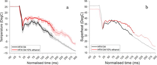
The degree of fluid superheat plotted in was predicted by taking the difference of the fluid temperature measured in the spray orifice and the saturation temperature of the formulation as reported by Gavtash et al. (Citation2016b) and is shown in . Yildiz et al. (Citation2002) showed superheat values of a steady HFA134a liquid jet in the range of 43.4 °C–49.6 °C resulted in non-shattering jet transitioning to flare flashing behavior and then complete disintegration. When the predicted degree of superheat is at a maximum at the orifice exit, it is similar in magnitude to that reported by Yildiz and colleagues for a steady flow. This suggests that evaporation, or even flash atomization, may play a significant role in the droplet production at the spray orifice exit of the pMDI. It could be expected that for transient flows the superheat level required for flashing would be lower than steady flows due to the presence of additional instabilities and perturbations in the flow.
Flash atomization of the superheated liquid will contribute to vapor production, plume expansion and possibly nucleation of bubbles within the liquid (Sher, Bar-Kohany, and Rashkovan Citation2008). Rapid expansion of vapor bubbles in the two-phase fluid due to the pressure drop at the orifice exit will contribute to disintegration of the liquid annulus.
pMDI orifice flow regimes
Based on the internal flow visualizations made in this research, a new conceptual schematic of the spray orifice internal flow regime was developed, found in .
Figure 7. Conceptual schematic diagrams of pMDI spray orifice internal flow regimes.
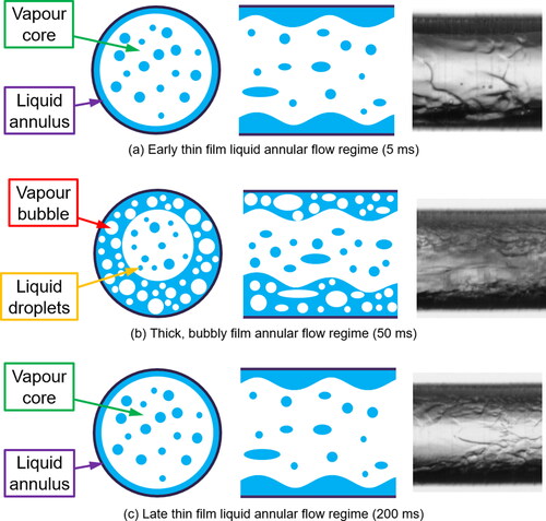
The early phase of the spray event () consists of a thin liquid annular film on the walls of the orifice surrounding a vapor core. The sonic vapor core causes waves or ripples on the surface of the liquid film. Droplets are likely stripped from the surface of the liquid film creating a disperse mist in the vapor core.
As the liquid fraction in the expansion chamber increases the thickness of the liquid annulus in the spray orifice also increases, to the extent that vapor bubbles are entrained and contained within the liquid (). The shearing action of the high velocity vapor core on the thick, bubbly liquid annulus causes mixing. Liquid stratification at the bottom of the sump leads to a stratified flow within the spray orifice with liquid flowing predominantly at the bottom. The liquid rich region breaks up along the length of the orifice due to the shearing action of the high velocity vapor core and internal mixing. The final phase of the spray event () is conceptually the same as the early phase but lasts for longer as the pressure and temperature of the fluid have reduced, and the metered dose is depleted.
The timescales over which each flow regime prevails will depend on actuator geometry and formulation composition, but the sequence of flow and spray production events will be substantially the same as reported here. We observed that the spray of the HFA134a/10% w/w ethanol formulation ended more abruptly than the pure HFA134a, leading to less erratic sputter of residual formulation. Visual analysis of high-speed videos was undertaken with further details and a pictographic temporal representation reported in Figure S13 of the supplemental information.
Large droplet production
Two large droplet production mechanisms have been identified, separate to the main atomization mechanism responsible for small respirable droplet production. A conceptual schematic diagram showing the two mechanisms (top and bottom) of large droplet production in a pMDI is presented in .
Figure 8. Schematic of large droplet production. (Top) Ligament stripping. (Bottom): Liquid slug ejection.
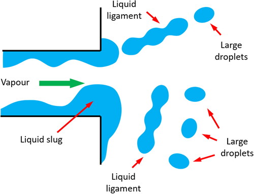
Large droplets are stripped from a liquid pool formed around the spray orifice exit during the actuation into the periphery of the spray plume, in the form of ligaments which subsequently break into droplets, as postulated by Versteeg and Hargrave (Citation2006).
Liquid slugs ejected from the spray orifice, predominantly as a result of unsteady liquid rich churn flow in the expansion chamber, break up in the near orifice region producing large droplets throughout the spray plume, as seen in and observed by Mason-Smith et al. (Citation2017).
Conclusions and areas for future work
Flow visualizations of two-phase fluid entering, flowing through, and exiting the orifice of a transparent model and a commercial pMDI actuator have been captured in higher detail than ever before. An annular orifice flow paradigm of a gaseous core in a liquid anulus has been shown confirming the observations of Versteeg and Hargrave (Citation2006). This orifice flow regime information and distribution of the liquid and gaseous phases will inform future pMDI modeling activities.
Schlieren imaging of the spray plume has shown for the first time, by the presence of shock diamonds, choked flow at the orifice exit. The first ever measurements of the fluid temperature inside the spray orifice enabled prediction of the degree of fluid superheat, which indicated that significant flash evaporation at the orifice exit is likely. Superheat driven flashing and expansion of the choked two-phase flow at the orifice exit result in a very wide plume, particularly at the start of the spray event.
The atomization mechanism of the pMDI is a hybrid of predominantly aerodynamic atomization with additional liquid flashing upon exit from the spray orifice. High aerodynamic shear forces result between the sonic gas flow at the core of the orifice and the annular liquid film. Images of the orifice internal flow and near orifice exit flow suggest that a near instantaneous transition of the two-phase fluid to liquid droplets in vapor occurs at the orifice exit. A new conceptual schematic of the time varying spray orifice flow regime has been developed based on observations of annular fluid flow made in this work.
Large irrespirable droplets are produced by two mechanisms; breakup of liquid slugs ejected from the orifice in the near orifice region and stripping of ligaments from a liquid pool formed around the orifice exit, which subsequently break up into large droplets in the periphery of the plume.
The present findings are intended to aid the pharmaceutical community in the swift transition to future high efficacy, low GWP pMDIs, to the ultimate therapeutic benefit of the patient. The increased detail and understanding of the atomization mechanism of the pMDI presented in this article will aid development current products but will also bring significant benefit to manufacturers seeking to formulate with alternative low global warming potential (GWP) propellants such as HFA152a or HFO1234ze(E) after the recent signing of the Kigali Amendment to Montreal Protocol (United Nations Environment Programme Citation2016).
It is expected that a similar hybrid aerodynamic and flashing atomization mechanism will dominate in pMDI systems utilizing low GWP propellants, given that the vapor pressures of these propellants are similar to those of the current HFA134a and HFA227ea gasses. However, differences in product performance (i.e., droplet size and velocity) are to be expected due to differences in physicochemical and thermodynamic properties (e.g., surface tension and viscosity) of formulations comprising HFA134a or HFA227ea compared to HFA152a or HFO1234ze(E). The extent to which the aerodynamic and flashing mechanisms manifest will likely be dependent, therefore, on the propellant selected.
Differences between pure HFA134a propellant systems, analogous to suspension-based systems, and solution-based systems containing ethanol have been observed. Ethanol in the formulation led to a bubbly internal fluid flow due to changes to the properties of the formulation, namely increased surface tension The change of fluid flow structure, effect on aerosol generation and development and therefore the effect on overall pMDI product performance of pMDIs formulated with low GWP propellants with and without and ethanol cosolvent is an area ripe for future research.
Supplemental Material
Download MS Word (8.5 MB)Disclosure statement
At the time of writing the article, BJM and BG are employees of Kindeva Drug Delivery. HKV and EJL are employees of Loughborough University. DL is employed at Oz-UK. TC is employed at Dyson Ltd. GKH and GB are retired. There are no declarations of interest.
References
- Brambilla, G., D. Ganderton, R. Garzia, D. A. Lewis, B. J. Meakin, and P. Ventura. 1999. Modulation of aerosol clouds produced by pressurised inhalation aerosols. Int. J. Pharm. 186 (1):53–61. doi: 10.1016/S0378-5173(99)00137-4.
- Brennen, C. E. 2005. Fundamentals of multiphase flows. 1st ed. Cambridge, UK: Cambridge University Press.
- Clark, A. R. 1991. Metered atomisation for respiratory drug delivery. PhD thesis, Loughborough University of Technology, Loughborough, UK.
- Dunbar, C. A. 1996. An experimental and theoretical investigation of the spray issued from a pressurised metered-dose inhaler. PhD thesis. UMIST, Manchester, UK.
- Everard, M. L. 2000. Aerosol therapy past, present, and future: A clinician's perspective. Respir. Care. 45 (6):769–76.
- Fletcher, G. 1975. Factors affecting the atomisation of saturated liquids. PhD thesis. Loughborough University of Technology, Loughborough, UK.
- Ganderton, D., D. A. Lewis, R. Davies, B. J. Meakin, G. Brambilla, and T. Church. 2002. Modulite: A means of designing the aerosols generated by pressurized metered dose inhalers. Respir. Med. 96 Suppl D (Suppl D):S3–S8. doi: 10.1016/S0954-6111(02)80018-X.
- Gavtash, B. 2016a. CFD simulation of pressurised metered-dose inhaler (pMDI). PhD thesis. Loughborough University, UK.
- Gavtash, B., B. Myatt, H. O’Shea, F. Mason, D. Lewis, T. Church, H. K. Versteeg, G. Hargrave, and G. Brambilla. 2016b. Saturated vapour pressure (SVP) measurement of ethanol/HFA binary mixtures. J. Aeros. Med. Pulmon. Drug Deliv. 29 (3):A12–A12.
- Huber, M. L, and M. O. McLinden. 1992. Thermodynamic properties of R134a (1,1,1,2-tetrafluoroethane) International Refrigeration and Air Conditioning Conference. Paper 184.
- Ivey, J. W., R. Vehring, and W. H. Finlay. 2015. Understanding pressurized metered dose inhaler performance. Expert Opin. Drug Deliv. 12 (6):901–16. doi: 10.1517/17425247.2015.984683.
- Lefebvre, A. H, and V. G. McDowell. 2017. Atomization and sprays, 2nd ed. Boca Raton, FA: CRC Press.
- Lewis, D. A. 2007. Metered-dose inhalers: actuators old and new. Expert Opin. Drug Deliv. 4 (3):235–45. doi: 10.1517/17425247.4.3.235.
- Love, E. S., Grigsby, C. E., Lee, L. P., Woodling, M. J. 1956. Experimental and theoretical studies of axisymmetric free jets. Hampton, VA, US: NASA Langley Research Center.
- Mason-Smith, N., D. Duke, M. Fedrizzi, J. Soria, D. Edgington-Mitchell, and D. Honnery. 2015. Back-illumination imaging of pressurised metered- dose inhaler sprays. In Australian Conference on Laser Diagnostics in Fluid Mechanics and Combustion (Damon Honnery and Daniel Edgington-Mitchell 09 December 2015 to 11 December 2015), Monash University Publishing, pp 45–50.
- Mason-Smith, N., D. J. Duke, A. L. Kastengren, D. Traini, P. M. Young, Y. Chen, D. A. Lewis, D. Edgington-Mitchell, and D. Honnery. 2017. Revealing pMDI spray initial conditions: flashing, atomisation and the effect of ethanol. Pharm. Res. 34 (4):718–29. doi: 10.1007/s11095-017-2098-2.
- Myrdal, P. B., P. Sheth, and S. W. Stein. 2014. Advances in metered dose inhaler technology: Formulation development. AAPS Pharm. Sci. Tech 15 (2):434–55. doi: 10.1208/s12249-013-0063-x.
- Myatt, B. J, et al. 2015a. PDA analysis of HFA/ethanol pMDI aerosols : an improved test protocol and new findings. ICLASS 2015, 13th International Conference on Liquid Atomization and Spray Systems, pp.1–7.
- Myatt, B. J, et al. 2015b. PDA and high speed image analysis of HFA/ethanol pMDI aerosols: new findings. In Drug delivery to the Lungs 26. Edinburgh, UK: The Aerosol Society; p. 73–7.
- Myatt, B. J. 2017. A fundamental study of the primary atomisation mechanism and aerosol plume development of the pressurised metered dose inhaler. PhD thesis. Loughborough University, Loughborough, UK.
- Myatt, B. J., S. W. Stein, and B. Gavtash. 2021. Pressure and temperature measurements of current and future low GWP pMDI propellants in the actuator sump. J. Aeros. Med. Pulmon. Drug Deliv. 34 (3):A-1–21.
- Newman, S. P. 2005. Principles of metered-dose inhaler design. Respir. Care. 50 (9):1177–90.
- Park, B. S, and S. Y. Lee. 1994. An experimental investigation of the flash atomization mechanism. Atomiz. Spr. 4 (2):159–79. doi: 10.1615/AtomizSpr.v4.i2.30.
- Shekunov, B. Y., P. Chattopadhyay, H. H. Y. Tong, and A. H. L. Chow. 2007. Particle size analysis in pharmaceutics: principles, methods and applications. Pharm. Res. 24 (2):203–27. doi: 10.1007/s11095-006-9146-7.
- Sher, E., T. Bar-Kohany, and A. Rashkovan. 2008. Flash- Boiling Atomization. Progress Energy Combust. Sci 34 (4):417–39. doi: 10.1016/j.pecs.2007.05.001.
- Stahlhofen, W., G. Rudolf, and A. C. James. 1989. Intercomparison of experimental regional aerosol deposition data. J. Aeros. Med. 2 (3):285–308. doi: 10.1089/jam.1989.2.285.
- Stein, S. W, and B. J. Gabrio. 2000. Understanding throat deposition during cascade impactor testing. Respir. Drug Deliv. VII 2 (4):287–90.
- Stein, S. W, and C. G. Thiel. 2017. The history of therapeutic aerosols: a chronological review. J. Aerosol Med. Pulm. Drug Deliv. 30 (1):20–41.
- United Nations Environment Programme. 2016. The Kigali Amendment to the Montreal Protocol: Another Global Commitment to stop climate change — UNEP Regional Office for Africa. Accessed October 2, 2022. //www.unep.org/news-and-stories/news/kigali-amendment-montreal-protocol-another-global-commitment-stop-climate
- Versteeg, H. K, and G. K. Hargrave. 2006. Fundamentals and resilience of the original MDI actuator design. In Respiratory Drug Delivery X, 91–100. Boca Raton, FL: Davis Healthcare International Publishing.
- Versteeg, H. K., G. K. Hargrave, and M. Kirby. 2006. Internal flow and near-orifice spray visualisations of a model pharmaceutical pressurised metered dose inhaler. J. Phys: Conf. Ser. 45:207–13. doi: 10.1088/1742-6596/45/1/028.
- World Health Organisation. 2021. Asthma fact sheet. Accessed October 2, 2011. //www.who.int/news-room/fact-sheets/detail/asthma
- Yarbrough, J., L. E. Mansfield, and S. Ting. 1985. Metered dose inhaler induced bronchospasm in asthmatic patients. Ann. Allergy. 55 (1):25–7.
- Yildiz, D., P. Rambaud, J. Van Beeck, and J.-M. Buchlin. 2002. A study on the dynamics of a flashing jet. Final Contract Research Report EAR0030, VKI.