Abstract
In ventilation ducts the turbulent flow profile is commonly disturbed or not fully developed, and these conditions are likely to influence particle deposition to duct surfaces. Particle deposition rates at eight S-connectors, in two 90° duct bends and in two ducts where the turbulent flow profile was not fully developed were measured in a laboratory duct system with both bare steel and internally insulated ducts with hydraulic diameters of 15.2 cm. In the bare-steel duct system, experiments with nominal particle diameters of 1, 3, 5, 9, and 16 μm were conducted at each of three nominal air speeds: 2.2, 5.3, and 9.0 m/s. In the insulated duct system, deposition of particles with nominal diameters of 1, 3, 5, 8, and 13 μm was measured at nominal air speeds of 2.2, 5.3 and 8.8 m/s. Fluorescent techniques were used to measure directly the deposition velocities of monodisperse fluorescent particles to duct surfaces. Deposition at S-connectors, in bends, and in straight ducts with developing turbulence was often greater than deposition in straight ducts with fully developed turbulence for equal particle sizes, air speeds, and duct surface orientations. Deposition rates at all locations were found to increase with an increase in particle size or air speed. High deposition rates at S-connectors resulted from impaction, and these rates were nearly independent of the orientation of the S-connector. Deposition rates in the two 90° bends differed by more than an order of magnitude in some cases, probably because of the difference in turbulence conditions at the bend inlets. In straight sections of bare steel ducts where the turbulent flow profile was developing, the deposition enhancement relative to fully developed turbulence generally increased with air speed and decreased with downstream distance from the duct inlet. This enhancement was greater at the duct ceiling and wall than at the duct floor. In insulated ducts, deposition enhancement was less pronounced overall than in bare steel ducts. Trends that were observed in bare steel ducts were present, but weaker, in insulated ducts.
INTRODUCTION
Particle deposition to duct surfaces occurs at several locations within a ventilation system, but deposition has only been well studied for fully developed turbulent flows. Flow paths through ventilation ducts are commonly complex and usually include several branches and bends. The turbulent flow profile in a straight duct section after a bend is asymmetrical and changes with distance downstream of the bend until it is once again fully developed. Transition elements, temperature control coils, dampers, and other components disturb flow profiles, further complicating most ventilation duct flows. Duct components and ridges at joints between duct sections are sites where particles may deposit by impaction. A significant proportion of the total deposition in ventilation systems is likely to occur at locations other than on the surfaces of straight ducts where turbulent flow profiles are fully developed. Because of the large numbers of flow disturbances and the potentially large effect on local deposition rates, experimental evidence of how deposition rates change with particle size and air speed at locations with disturbed turbulent flow is essential to evaluate losses of airborne particles as they travel through ventilation ducts.
Ducts in commercial buildings are usually made of galvanized steel. Commonly, some ducts have internal fiberglass insulation to reduce noise transmission and to provide a thermal barrier. Most ventilation duct runs consist of several short sections connected in series. Mechanical connectors at joints between these sections, such as S-connectors, can cause internal ridges that project a few millimeters into the duct flow and provide surface area for particles to deposit by impaction. Deposition at ridges resulting from duct connections has not been investigated experimentally, but the similar case of deposition to repeated transverse ribs on duct floors has been studied (CitationChamberlain et al. 1984; CitationLai 1997). These studies used ribs that were larger and more closely spaced than the ridges that result from duct S-connectors. Nevertheless, the results suggest that S-connectors may significantly influence local particle deposition rates.
Because of the different flow conditions and the potential for particle deposition by inertial impaction, deposition rates in bends are likely to be different than those in straight ducts. Until recently, experimental reports of deposition from turbulent flow within bends were limited to investigations in small diameter tubes (CitationPui et al. 1987; CitationMcFarland et al. 1997). Deposition rates of 1–10 μm particles in these small tube bends were higher than most measured rates in straight tubes. CitationPeters and Leith (2004) investigated the deposition of 5–150 μm glass particles in 15 cm diameter duct bends under a variety of configurations and found broad disagreement with the deposition rates previously measured in small tubes.
Particle deposition from turbulent flow is sensitive to the character of the flow and to the degree of turbulence. Much of the turbulent flow in ventilation ducts does not have a fully developed flow profile because of the frequent occurrence of branches, bends, and transitions. The distance for a turbulent flow profile to become fully developed after a disturbance is typically 40–100 hydraulic duct diameters (CitationHinze 1975). Because particle deposition from turbulent flows depends on the nature of the turbulence, deposition rates in ventilation systems are likely to vary with location along the length of a duct run.
Particle deposition from disturbed or undeveloped turbulent flows has not been the subject of systematic experimental investigation. Several researchers have noted differences between deposition rates from fully developed and developing turbulent flows, but reports are inconsistent. CitationLiu and Agarwal (1974) noted significantly less deposition at the inlet of small tubes than at locations where the turbulence was fully developed. CitationChamberlain (1966) reported vapor deposition rates for the first six diameters of length in a large duct that were up to twice the rates in fully developed flow. CitationSehmel (1968) reported deposition rates of 16 μm particles that were dramatically enhanced near the inlet of a small tube compared to the rest of the tube. Particle deposition rates in straight duct sections after bends have not been reported. In this article, measurements of particle deposition in a laboratory duct system to S-connectors at duct junctions, in duct bends, and in straight ducts where the turbulent flow profile was not fully developed are presented and discussed. The measurements reported here were made during the same experimental runs reported in CitationSippola and Nazaroff (2004).
METHODS
Definitions
The deposition velocity, V d (m s−1), of a particle to a duct surface is defined as
The dimensionless deposition velocity is defined as follows:
The relaxation time of a particle is the characteristic time for the particle velocity to respond to a change in the local air velocity. Neglecting particle slip (appropriate for supermicron particles at ambient pressure and temperature), a dimensionless particle relaxation time, τ+ , may be calculated for spherical particles in the Stokes flow regime as follows:
Experimental Approach
Particle deposition in bare steel and in insulated ducts was measured at a variety of locations within a laboratory system for particle sizes in the range of 1–16 μm and for air speeds in the range of 2.2–9.0 m/s. In the bare steel system, experiments were performed at three nominal air speeds—2.2, 5.3, and 9.0 m/s—for each of five nominal particle diameters: 1, 3, 5, 9, and 16 μm. Including one replicate adjust experiment, a total of sixteen experiments were conducted in the bare steel system (runs 1–16). In the insulated system, experiments were performed at three nominal air speeds—2.2, 5.3, and 8.8 m/s—for each of five nominal particle diameters: 1, 3, 5, 8, and 13 μm. Fifteen distinct experiments were conducted in the insulated system (runs 17–31). All experiments were conducted at atmospheric pressure and at a room temperature in the range 21–26°C.
A side-view schematic of the experimental apparatus is given in ; detailed descriptions have been reported of the apparatus and experimental methods, as well as results of particle deposition measurements made in ducts with a fully developed turbulent flow profile (CitationSippola and Nazaroff 2004). Briefly, monodisperse experimental particles tagged with a fluorescent tracer (ammonium fluorescein) were injected into the duct system at the mixing box. Particles were produced by means of a vibrating orifice aerosol generator (TSI Inc., Model 3450) and a Boltzmann charge distribution was imparted on the aerosol by passing it through a neutralizer (TSI Inc., Model 3054) with a Kr-85 radioactive source. Particles were generated from a liquid solution of isopropyl alcohol, oleic acid, and solid sodium fluorescein dissolved in 0.1 M aqueous ammonium hydroxide. Particles larger than 1 μm comprised a suspension of ammonium fluorescein in oleic acid; 1 μm particles were solid ammonium fluorescein. Particle deposition was measured at two horizontal duct sections where the turbulent flow profile was fully developed (test ducts 1 and 2), at eight S-connectors (associated with test ducts 1 and 2), at two straight horizontal duct sections where the turbulent flow profile was not fully developed (test ducts 3 and 4), and at two 90° duct bends (bends 5 and 6).
FIG. 1 Side-view schematic diagram of the experimental apparatus (not to scale). Straight duct sections are square in crosssection, 15 cm on a side by 152 cm long. The inset shows a close-up side view of an S-connector between two duct sections.
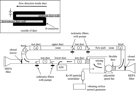
Time-averaged airborne particle concentrations were measured immediately upstream and downstream of test ducts 1 and 2. Isokinetic nozzles continuously delivered aerosol from the duct centerline to 47 mm nitrocellulose filters for the duration of an experiment. An aerodynamic particle sizer (APS; TSI Inc., Model 3320) continuously sampled the experimental aerosol at the centerline of the lower duct through a specially designed, shrouded sampling nozzle. Aerodynamic particle size data collected by the APS were used to calculate the mean physical diameter of particles during each experiment.
Airborne particle concentrations and particle surface fluxes were quantified by fluorescent techniques in a wet-chemistry lab. Filters, S-connectors, duct surfaces, and interior portions of nozzles and filter holders were each rinsed with a known amount of solution in a glass tray or Pyrex beaker. The fluorescence of the resulting wash solution was measured by means of a fluorometer (Turner Designs, Model TD-700). Recovery experiments were conducted to ensure that all fluorescein was removed from each surface in the rinsing process.
Eight S-connectors were analyzed for particle deposition after each experiment for runs 1–16 in the steel system: four associated with test duct 1 and four associated with test duct 2. Test duct 1 had two S-connectors horizontally oriented on the duct floor (one each at the upstream and downstream ends) and two oriented horizontally on the ceiling. All four S-connectors associated with test duct 2 were vertically oriented on the walls.
Bends 5 and 6 were not internally insulated in any experiments; the same galvanized steel bends were used in both the bare steel and insulated systems. The bends had a bend radius of 22.9 cm (9.0 in) measured at the centerline. Bend 5 was located immediately after another 90° bend associated with the branched section in the lower duct. Bend 5 changed the flow direction from vertical and upwards to horizontal. Bend 6 was located at the end of the long, straight upper duct and directed the flow to make a right turn in the horizontal plane. When bends were analyzed, deposition to the entire internal surface was measured and no distinctions were made among deposition rates to ceiling, wall, or floor surfaces.
Test duct 3 was located immediately after the outlet from the mixing box in the lower duct. Test duct 4 was located immediately after bend 5 in the upper duct. The flow in these ducts was always turbulent, but as a consequence of upstream flow perturbations, the turbulent flow profile was not fully developed. There is somewhat greater uncertainty in deposition velocities measured in test ducts 3 and 4 than in test ducts 1 and 2 because airborne concentrations were not measured directly at test ducts 3 and 4. Duct panels to be analyzed for particle deposition were cut from the test ducts using electric sheet metal shears. For each test duct, twelve panels were removed and analyzed: four panels each from the duct floor, sidewall, and ceiling. The four panels were centered at locations that were 0.30, 0.61, 0.91, and 1.22 m (1.0, 2.0, 3.0, and 4.0 ft) from the test duct inlet and were numbered 1–4 beginning at the duct inlet. Cut panels were rectangular and typically measured about 0.1 × 0.2 m. The panel numbering convention is the same as described in of CitationSippola and Nazaroff (2004).
Data Analysis
Airborne concentrations and deposition velocities measured at test ducts 1 and 2 were used to estimate particle concentrations throughout the experimental apparatus. Airborne concentrations at test ducts 3 and 4 were needed to calculate particle deposition velocities at these locations. Airborne concentrations at the inlet or outlet of bends 5 and 6 were needed to evaluate particle penetrations through these bends.
Deposition velocities measured for each surface in test ducts 1 and 2 for a given particle size and air speed were averaged. These values were subjected to surface-area-weighted averaging to yield a composite deposition velocity, V d,comp , for a horizontal duct. Particle penetration through straight horizontal sections of the experimental duct could then be estimated by the following equation:
S-connectors
Deposition velocities for S-connectors at test ducts 1 and 2 were calculated by EquationEquation (1) using the measured airborne concentration at the appropriate location. The length and width of each S-connector were 14.1 cm and 2.7 cm, respectively, giving a deposition area of 38.1 cm2. Dimensionless deposition velocities to S-connectors on the duct ceiling, wall, and floor were respectively termed ,
, and
.
Observations during the rinsing of S-connectors for fluorescence analysis suggested that, for most particle sizes, the majority of particle mass was deposited at the leading edge presented to the airstream. Thus, S-connector deposition fractions were also estimated. The S-connector deposition fraction, η S , was defined by
The dimensionless distance from a wall, y+ , is defined by
Bends
Penetration through bends, P bend , was calculated by the following equation:
Ducts with developing turbulent flow
In test ducts 1 or 2, where the turbulent flow profile was fully developed, the measured particle deposition fluxes to each panel of a given duct surface were approximately equal. Deposition rates measured in test ducts 1 and 2 are presented in CitationSippola and Nazaroff (2004). In contrast, measured deposition rates to the four panels of a given surface in test duct 3 or 4 usually showed a trend of decreasing deposition flux with increasing downstream distance (as indicated by panel number). It was deemed useful to report deposition rates in these ducts in terms of an enhancement factor rather than as an average of the deposition velocities measured to each panel of a given surface.
The enhancement factor, EF, is the ratio of the measured deposition velocity to a panel in a duct with a developing turbulent flow profile (test duct 3 or 4) to the average deposition velocity in ducts with fully developed turbulent flow profiles (test ducts 1 and 2) for the same particle size and air speed. For example, the enhancement factor in test duct 4 for the second ceiling panel is
RESULTS
S-connectors
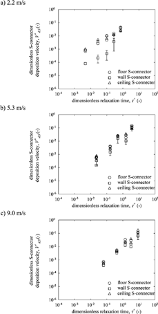
Average measured S-connector deposition fractions in the steel system are presented in . illustrates how the dimensionless deposition velocities to S-connectors vary with τ+ at air speeds of 2.2, 5.3, and 9.0 m/s. In this figure, each measurement of deposition to an S-connector on the duct floor or ceiling is shown as a single data point. Data points representing deposition to wall S-connectors are the average of four measurements with error bars representing measurement variability. Error bars are only included when they are significantly larger than the size of the data point. displays measured S-connector deposition fractions versus S-connector Stokes numbers.
FIG. 3 S-connector deposition fraction versus connector Stokes number for S-connectors on the ceiling, wall, and floor at the three nominal air speeds.
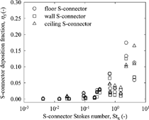
TABLE 1 Average S-connector deposition fractions in the bare steel duct systemFootnote a
Bends
summarizes measured bend penetrations for all experiments. Penetrations through bends 5 and 6 versus the bend Stokes number are shown in . Composite dimensionless deposition velocities in bends are compared to those in straight ducts in . The composite dimensionless deposition velocities for bends are averaged over the entire internal surface area of the bend; those reported for straight ducts are surface-area-weighted averages of deposition velocities measured to the floor, wall, and ceiling of test ducts 1 and 2 in the bare steel system. The surface-area-weighted averaging was performed to make the data in the straight ducts directly comparable to the data in the bends.
FIG. 4 Penetration through (a) bend 5 and (b) bend 6 versus bend Stokes number for all air speeds in both the bare steel and insulated systems.
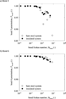
FIG. 5 Composite dimensionless deposition velocities in (a) bend 5 and (b) bend 6 compared to dimensionless deposition velocities in straight steel ducts at nominal air speeds of 2.2 m/s, 5.3 m/s, and 9.0 m/s.
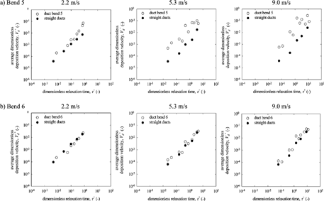
TABLE 2 Measured bend penetrations for all experimentsFootnote a
Ducts with Developing Turbulent Flow
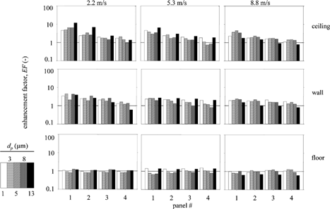
Measured dimensionless deposition velocities to all panels of test duct 4 in both the bare steel (runs 1–16) and insulated (runs 17–31) systems are presented in . display all enhancement factors measured in test duct 4, in the bare steel and insulated systems, respectively. In these figures, the plots in the left, middle, and right columns display data collected at the low, intermediate, and high air speeds, respectively. The top, middle, and bottom rows of plots display data collected at the duct ceiling, wall, and floor, respectively. The uncertainties in the reported enhancement factors have been estimated to be in the range 5–15% (CitationSippola 2002). Data with similar results to those shown in and were collected in test duct 3 (CitationSippola 2002).
TABLE 3 Dimensionless deposition velocities for all panels in test duct 4 for all experimentsFootnote a Footnote b
DISCUSSION
S-connectors
Dimensionless deposition velocities to S-connectors () increased with values of τ+ for all air speeds and for S-connectors located on all duct surface orientations. In most cases, measured deposition rates to S-connectors at all three surfaces were within the same order of magnitude for a given airspeed and particle size. It was observed during wet chemistry analysis that most of the particle mass on S-connectors was deposited at the leading edge presented to the airstream, especially for larger particles. These observations suggest that impaction on the leading edge is the mechanism by which most particles deposited to S-connectors.
Measured deposition rates to ceiling and wall S-connectors were higher than those measured to the corresponding bare steel duct surface to which the S-connector was attached. A comparison of the data reveals that deposition velocities to ceiling S-connectors was greater than deposition velocities to the bare steel duct ceiling by factors of 30–520. Deposition to wall S-connectors was greater than deposition to the bare steel duct wall by factors in the range 1.5–48. Measured deposition rates to S-connectors on the floor were about the same as those measured to the bare steel duct floor.
Measured deposition velocities to the wall S-connectors were generally lower than those measured to S-connectors on the floor and ceiling; this trend is most visible at the lowest air speed where data for the wall S-connectors lie about an order of magnitude lower than the other data for most particle sizes. There is no clear explanation for the lower deposition rates to wall S-connectors relative to S-connectors at floors and ceilings. However, this result may reflect the influence of gravitational settling and the lesser horizontal surface available on wall connectors. For this explanation to be valid, some flow must penetrate the small gap between the S-connector and the duct. Deposition of 1–16 μm particles in this laminar flow environment would be dominated by gravitational settling, which could occur at the upward-facing inner surfaces of S-connectors at floors and ceilings but could not occur at S-connectors located on walls because they are vertically oriented. If flow leakage behind the connector did not occur, then the observation that measured deposition rates to S-connectors on both the floor and ceiling had similar values is an indication that gravitational settling was not dominant for deposition to these surfaces.
The data in exhibit scatter but follow the same trends as other particle deposition processes that are dominated by impaction, such as to fibers. For S-connector Stokes numbers less than 0.1, deposition fractions were very close to zero. Deposition fractions increased gradually as the Stokes number increased from 0.1 to 1, and then increased more dramatically as the Stokes number increased above 1.
Bends
The data in show that, in general, penetration through bend 5 and bend 6 decreased with an increase in particle size or air speed. There is reasonable agreement among data collected in the bare steel and insulated systems. The trends are observed in both data sets, but these trends are most clear in the data collected in the bare steel system. Compared to bend 5, measured penetration values through bend 6 were generally higher and less scattered. Bend 6 had more floor surface area than bend 5 and therefore, in contrast to observations, might have been expected to yield lower values for particle penetration. The likely cause of the higher penetration values through bend 6 is the difference in inlet conditions between the two bends. The flow at the inlet of bend 6 was relatively undisturbed, but bend 5 was preceded by a duct branch and another bend, both of which were likely to increase the degree of turbulence in the flow. This higher degree of turbulence may have led to higher particle deposition in bend 5 and therefore to lower particle penetration.
In , particles with bend Stokes numbers less than 0.01 have values for penetration through both bends nearly equal to 1. Bend penetrations begin to decrease for increasing values of Stbend, and this decrease is more dramatic in bend 5 than in bend 6. That the data are fairly well correlated with particle Stokes number suggests that particle inertia is an important factor in determining deposition in bends. Turbulent eddies that impinge on duct surfaces are likely to be much more common in bends, where the mean flow direction is changing, than in straight ducts. Particles associated with these impinging eddies may deposit to surfaces by impaction if they have sufficient inertia. The relatively strong secondary flows established within bends offer additional opportunities for deposition of particles by inertial impaction.
In , which compares average dimensionless deposition velocities within bend 5 to the equivalent surface-area-weighted dimensionless deposition velocities within straight steel test ducts 1 and 2, the deposition rates in the bend are seen to be greater than in the straight ducts for all particle sizes and air speeds. The increase in deposition rates in bend 5 over deposition rates in the straight ducts was greatest at the highest air speeds, where the increase for most particle sizes was one to two orders of magnitude. Increases in dimensionless deposition velocities in bend 6 over equivalent surface-area-weighted values to straight steel ducts were less dramatic than in bend 5, as can be seen in . At the lowest air speed, deposition rates in bend 6 were about equal to those in straight ducts. At the higher air speeds, deposition rates in bend 6 were greater than rates in straight steel ducts by factors that were always less than four.
Ducts with Developing Turbulent Flow
One trend visible in is that, for a given particle size, enhancement factors increase with increasing air speed. Enhancement factors were larger for the ceiling and wall than for the floor, especially at the higher air speeds. Essentially no enhancement was observed at the floor of test duct 4 for all air speeds. Deposition trends similar to those observed in test duct 4 were also observed in test duct 3.
FIG. 6 Enhancement factors at the ceiling, wall, and floor at panels in duct 4 in the bare steel system at three air speeds. Panels measure approximately 10 cm × 20 cm and are centered 30, 61, 91, and 122 cm downstream from the leading edge of a duct. See CitationSippola and Nazaroff (2004) for additional details.
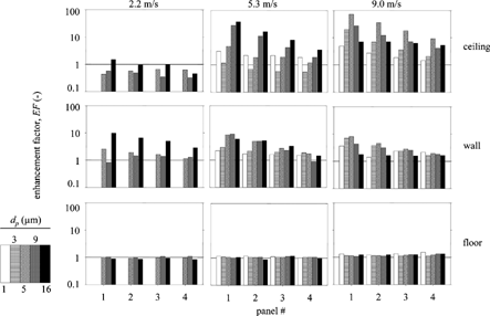
The upper right panel of displays enhancement factors at ceiling panels of test duct 4 at an air speed of 9.0 m/s. The increase in deposition rates at this location relative to the case of deposition from flow with a fully developed flow profile is apparent. Enhancement factors are expressed relative to the deposition rate of the same-sized particle to the same surface and at the same velocity in a duct with fully developed turbulent flow. For example, at an air speed of 9.0 m/s, 5 μm particles were observed to deposit to ceiling panel 1 of duct 4 at a rate 72 times higher than they deposited to ceiling panels in ducts 1 and 2. The other prominent feature of this panel is the decrease in the enhancement factor from upstream to downstream locations for all particle sizes. This trend is weakest at the largest particle size. The large enhancement factors at the ceiling of test duct 4 were likely attributable to the vertically oriented bend immediately upstream of this test duct. Air flowing through this bend would have impinged on the ceiling surface of test duct 4, giving entrained particles the opportunity to deposit by impaction more readily than in a flow with a symmetrical velocity profile. In most cases, enhancement factors at the furthest downstream position (panel 4) are near one, indicating that deposition rates relax rapidly to about the same values as in ducts with fully developed turbulence, even within one duct length (∼10 D h ) of a flow disturbance.
As seen in , enhancement factors in the insulated system were generally smaller than those measured in the bare steel system for test duct 4. This was probably a result of the high deposition rates to insulated duct surfaces from fully developed turbulent flow. In the insulated system there is no apparent trend of increased enhancement factor with increasing air speed for test duct 4, but the data do show decreasing enhancement with increasing panel number.
FIG. 7 Enhancement factors at the ceiling, wall, and floor at panels in duct 4 in the insulated system at three air speeds. Panels measure approximately 10 cm × 20 cm and are centered 30, 61, 91, and 122 cm downstream from the leading edge of a duct. See CitationSippola and Nazaroff (2004) for additional details.
CONCLUSIONS
Experiments were conducted that used fluorescent techniques to quantify particle deposition directly on the surfaces of a laboratory duct system constructed of materials typical of ventilation systems in real buildings. Experiments covered particle sizes in the range 1–16 μm and air speeds in the range 2.2–9.0 m/s in a steel and an internally insulated duct system. Measured deposition rates to S-connectors in duct bends and in ducts where the turbulent flow profile was not fully developed were generally greater than rates to equivalent surfaces in ducts with a fully developed turbulent flow profile. Impaction is the likely mechanism that contributes to the observed increase in particle deposition in all cases.
S-connectors were found to be sites of relatively high particle deposition owing to impaction on their leading edges. Deposition rates to S-connectors were dependent on both particle size and air speed, but were relatively independent of orientation. Deposition rates to S-connectors located on duct walls and ceilings were higher than deposition rates to duct surfaces of the same orientation. Particle penetration through bare steel 90° duct bends was found to decrease with increases in particle size or air speed. Penetration through bends was dependent on the airflow conditions at the bend inlet: penetration was lower where the inlet airflow was disturbed and higher when the inlet airflow was fully developed. In general, particle deposition rates in steel bends were greater than deposition rates in straight steel ducts. In the bare steel duct system particle deposition rates in a duct immediately after a bend and in a duct immediately after an inlet, locations where the turbulent profile was not fully developed, were generally greater than deposition rates in ducts with fully developed turbulence. Deposition rates in these ducts were measured to decrease with distance downstream. The degree to which deposition rates were enhanced in these ducts relative to ducts with fully developed turbulence increased with air speed. In the insulated system, similar trends were observed, but the degree of enhancement was generally less.
These experiments quantify particle deposition in ventilation ducts at locations that have not previously been studied. The results suggest that there are many locations within duct systems where particle deposition rates are significantly greater than deposition rates to ducts with fully developed turbulence. These experimental findings imply that models for predicting deposition rates within ventilation duct systems should account for sites with enhanced deposition.
Acknowledgments
This work was supported by the Office of Research and Development, Office of Nonproliferation and National Security, US Department of Energy under Contract No. DE-AC03-76SF00098.
Notes
a Symbol definitions:
a Symbol definitions:
a Symbol definitions: U ave - mean air speed through duct; d p - particle diameter; V+ d,c - dimensionless deposition velocity to a duct ceiling; V+ d,w - dimensionless deposition velocity to a duct wall; V+ d,f - dimensionless deposition velocity to a duct floor.
b Panels measure approximately 10 cm × 20 cm and are centered 30, 61, 91, and 122 cm downstream from the leading edge of a duct. See CitationSippola and Nazaroff (2004) for additional details.
REFERENCES
- Brodkey , R. S. and Hershey , H. C. 1988 . Transport Phenomena: A Unified Approach , New York : McGraw-Hill .
- Chamberlain , A. C. 1966 . Transport of Gases to and from Grass and Grass-like Surfaces . Proc. Roy. Soc. London Ser. A , 290 : 236 – 265 .
- Chamberlain , A. C. , Garland , J. A. and Wells , A. C. 1984 . Transport of Gases and Particles to Surfaces with Widely Spaced Roughness Elements . Boundary Layer Meteor. , 29 : 343 – 360 . http://www.csa.com/htbin/linkabst.cgi?issn=0006-8314&vol=29&iss=&firstpage=343 http://dx.doi.org/10.1007%2FBF00120534
- Hinze , J. O. 1975 . Turbulence , 2nd Ed. , New York : McGraw-Hill .
- Lai , C. K. 1997 . An Experimental Study of the Deposition of Aerosol on Rough Surfaces and the Implications for Indoor Air Quality Control , London , UK : Imperial College . Ph.D. Dissertation
- Liu , B. Y. H. ,. and Agarwal , J. K. 1974 . Experimental Observation of Aerosol Deposition in Turbulent Flow . Aerosol Sci. , 5 : 145 – 155 . http://www.csa.com/htbin/linkabst.cgi?issn=0278-6826&vol=5&iss=&firstpage=145 http://dx.doi.org/10.1016%2F0021-8502%2874%2990046-9
- McFarland , A. R. , Gong , H. , Muyshondt , A. , Wente , W. B. and Anand , N. K. 1997 . Aerosol Deposition in Bends with Turbulent Flow . Environ. Sci. Technol. , 31 : 3371 – 3377 . http://dx.doi.org/10.1021%2Fes960975c
- Peters , T. M. ,. and Leith , D. 2004 . Particle Deposition in Industrial Duct Bends . Ann. Occup. Hygiene , 48 : 483 – 490 . http://www.csa.com/htbin/linkabst.cgi?issn=0003-4878&vol=48&iss=&firstpage=483 http://dx.doi.org/10.1093%2Fannhyg%2Fmeh031
- Pui , D. Y. H. , Romay-Novas , F. and Liu , B. Y. H. 1987 . Experimental Study of Particle Deposition in Bends of Circular Cross Section . Aerosol Sci. Technol. , 7 : 301 – 315 . http://www.csa.com/htbin/linkabst.cgi?issn=0278-6826&vol=7&iss=&firstpage=301
- Sehmel , G. A. 1968 . Aerosol Deposition from Turbulent Airstreams in Vertical Conduits Report BNWL-578 , Richland , WA : Pacific Northwest Laboratory .
- Sippola , M. R. 2002 . Particle Deposition in Ventilation Ducts , Berkeley , CA : University of California . Ph.D. Dissertation
- Sippola , M. R. and Nazaroff , W. W. 2004 . Experiments Measuring Particle Deposition from Fully Developed Turbulent Flow in Ventilation Ducts . Aerosol. Sci. Technol. , 38 : 914 – 925 . http://dx.doi.org/10.1080%2F027868290507213
