This article reports airflow, particle transport, and pressure differential control of a front-opening unified pod/load port unit (FOUP/LPU) minienvironment system using both experimental and computational fluid dynamics (CFD) approaches. The stochastic tracking approach in the Discrete Phase Model of Fluent software was adopted to predict particle trajectory. The predicted velocity vectors were verified by experimental ones, which were measured by a 3D ultrasonic anemometer. Particles from the upper edge of the FOUP produce a greater contamination risk than those from the lower edge of the FOUP. Particles generated on the moving part of the LPU can be entrained to the back surface of wafer in the bottom position. The parameters that affect the pressure differential between the minienvironment and surrounding environment were analyzed. The minimum pressure differential required to prevent particles from ingression to the minienvironment was determined.
INTRODUCTION
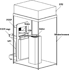
In line with improvement in production techniques, the rise in the number of 300 mm wafer-manufacturing factories is a natural trend. As opposed to factories producing the smaller 200 mm wafer, these factories use wafer loading/unloading modules with full front-opening unified pod/load port unit (FOUP/LPU) combined with minienvironment. The entire module is composed of three main components, namely a minienvironment, a LPU, and a FOUP, as illustrated in . Their main functions are detailed as follows. Minienvironment is a small-scale clean environmental mechanism housing the entire wafer production facilities to ensure that the processing of wafer is carried out in a controllable high level of cleanliness. Each production facility has its individual minienvironment whose clean air is provided by a fan filter unit (FFU) that maintains a positive pressure to form a unique isolated environment shielded from external contamination. The main function of the LPU is to open/close the door of the FOUP such that the wafer stored in the FOUP can be loaded into the manufacturing machine. Its main components are a FOUP stage and a front-opening interface mechanism (FIM). The FOUP is a container that stores the wafer and is sealed airtight to shelter the wafer from contact with the clean room environment in the conveying process to prevent particle contamination. In each FOUP there are a total of 25 pieces of wafer, and their positions are labelled from the bottom to the top in ascending order.
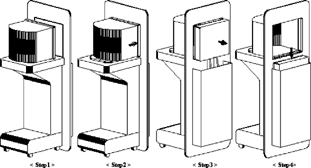
illustrates the docking processes of the FOUP to the minienvironment: first (process 1), the FOUP is placed on the FOUP stage; second (process 2), the FOUP is forwarded to contact with the FIM by the FOUP stage after the latch key of the FOUP door is closely connected to that of the FIM; third (process 3), by pushing the FIM the FOUP door is opened after the latch key fixing the FOUP door to the FOUP is removed; fourth (process 4), the FIM with FOUP door is lowered to the LPU. During docking, the FOUP is close in contact with the minienvironment, with a gasket between them. However, even with a very dedicated design, an air gap may exit between the FOUP and the minienvironment. If the docking is greatly impacted, particle production is anticipated.
Standard mechanical interface (SMIF) minienvironment for 200 mm wafer processing was comprehensively investigated for particle contamination, and it was found to match fully the corresponding specifications, such as particle per wafer pass (PWP) value and cleanliness level in the minienvironment. (Fosnight et al. 1998; Abu-Zaid 1997; Liu and Yoo 1996). Although several 300 mm wafer fabrication lines are operational, detailed knowledge of airflow and particle characteristics of a FOUP/LPU minienvironment still remains unavailable. Publications on the airflow and particle characteristics of the FOUP/LPU minienvironment system for 300 mm wafer manufacturing are rare. The I300I (1996) released by the SEMATECH provides dimension and size information of the FOUP and the LPU. However, it contains no information about regulating performance and testing method. Schneider et al. (1998) noted that particles generated at the perforated plate of the door-opening mechanism do not contaminate the wafer even with a slight overpressure (0.05 Pa). There is no information of clean room cleanliness level, nor was a particle challenge test conducted. Kobayashi et al. (2000) performed PWP testing on particles with diameters ≥0.12 μ m, for wafers in the FOUP during the opening of the FOUP door. They reported that the PWP value of the top wafer (wafer 25) is the highest. Moreover, the cleanliness of the clean room and the speed at which the door is opened are the two factors that most strongly affect the PWP value. However, the PWP test cannot identify the effect of individual sources of particles on the surfaces of the FOUP and the wafer. The authors believe that research must be continued for the following reasons. First, no study has provided detailed information about airflow pattern, such as the magnitude of air velocity, the number of flow vortices, or the sizes of vortices, when wafers are placed in various positions such as top, middle, or bottom positions. Second, previous studies have not involved particle challenge tests, which are very important in evaluating the influence of the source of particles on the risk of contamination. Without challenge particles, a small number of particles may not be detected because the sampling sensitivity of the particle-detecting machine is limited. Third, to our knowledge no literature has provided information on pressure control on particles in a FOUP/LPU minienvironment system for fabricating 300 mm wafers.
This study therefore aims to use both experimental and computational fluid dynamics (CFD) approaches to achieve the following:
| 1. | to elucidate airflow and particle transport characteristics in a FOUP/LPU minienvironment system when the bottom, middle, and top wafers are extracted in the minienvironment; and | ||||
| 2. | to recognize the most influential factor leading to the variation in pressure differential between the minienvironment and the clean room, and to determine the minimum pressure differential for keeping the FOUP from ingression of contamination. | ||||
RESEARCH APPROACHES
Experimental Setup
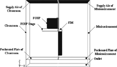
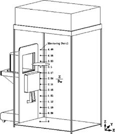
The experimental setup of the FOUP/LPU minienvironment system is schematically illustrated in . The minienvironment has a dimension of 0.7 m wide by 1.0 m long by 1.6 m high. The system was located in a class 1000 cleanroom (@ 0.3 μm) at a temperature and relative humidity of 22 ± 1ˆC and 45 ± 5% relative humidity (RH), respectively. The minienvironment was constructed from dust-free and antielectrostatic material. The FFU above the minienvironment provides 0.35 m/s downflow velocity (filter face velocity) and 99.99997% particle capture efficiency. Perforated plates with adjustable dampers were installed in both cleanroom and floor of minienvironment. The airflow vectors were measured by a 3D ultrasonic anemometer (KAIJO model FA600). The accuracy of the ultrasonic anemometer is within ±2% full scale (1.0 m/s) when the probe is aligned with the main air velocity direction after zero velocity adjustment. Based on the 95% confidence limits, the uncertainties of the mean velocities along x, y, and z directions and the resultant mean velocity are estimated to be 8.7%, 3.2%, 2.8%, and 7.2%, respectively. The uncertainty of the standard deviation of the velocity in x, y, and z directions is within 2.2%. As the anemometer probe was of finite size, measurements were taken in the central plane that intersects the FOUP door. He-Ne laser particle counters (Met-One Model Royco 330B with 0.1 cfm sampling flow rate) were used to measure the particle concentration for particle diameters of 0.1 μ m, 0.2 μ m, 0.3 μ m, 0.5 μ m, 0.7 μ m, and 1 μ m. Since the ultrasonic vibrator was used to generate particles using polystrene latex sphere (PSL) as the particle source (injection velocity can be neglected) with more than 75% of 0.2 μ m diameter particles, the concentration produced at the source point was approximately 106 particles/ft3.
CFD Model
The CFD study was performed using a 3D computer code—FLUENT (version 5.0, 1998)—which has been extensively validated in solving various types of turbulent flows. The governing equations were solved by the semi implicit method for pressure-linked equation (SIMPLE) algorithm that was described by Patankar (1980). The standard κ-ϵ two-equation model of turbulence was applied in this study. The effective viscosity μ e is defined as
where μ is the molecular viscosity, and μ t is the turbulent viscosity, and is defined as
After the velocity field was solved, the trajectories of discrete-phase particles were predicted by the stochastic tracking approach using the solved velocity data. This was done by integrating the force balance on the particles, which was expressed in a Lagrangian reference frame. The particle diameter considered in CFD is 0.2 μ m. The dispersion of such submicron particles is strongly affected by the fluctuation velocity. These turbulence fluctuations are random functions of space and time. However, this feature of submicron particles was not included in the work of Schneider et al. (1998). The trajectory of a discrete-phase particle is predicted by integrating the force balance on the particle, which is expressed in a Lagrangian reference frame. It is noted that the dispersion of submicron particles is strongly affected by the instantaneous fluctuation velocity. These turbulence fluctuations are random functions of space and time. Assuming homogeneous turbulence, we can calculate the fluctuating velocities of air from the kinetic energy of turbulence:
where ζ is a normally distributed random number ranging from 0 to 1 and k is the turbulent kinetic energy. For small particles that move with the fluid, the integral time scale becomes the fluid Lagrangian integral time scale, T L . This time scale can be approximated as
The equation of motion of a submicron particle is given by
The entire 3D domain was solved. To simplify the simulation, several assumptions were introduced as follows: (1) the flow was an incompressible, isothermal, and 3D steady-state turbulent flow; (2) the particles were spherical solid particles; (3) no interaction occurred between the continuous and discrete phases; and (4) the influence of robot on airflow was neglected. The boundary conditions imposed were the standard practices used in numerical computations. shows the boundary conditions. For the supply inlet, the boundary conditions specified for the continuous phase (air) in this study were defined as follows: the supply inlet flow of the FFU is defined as entering the minienvironment with a uniform velocity and particle concentration, that is w
i
= 0.35 m/s, u
i
= v
i
= 0.0 m/s and C
i
= 0.0 particle/m3. The values of k and ϵ were k = 0.002 w
i
2 and with the mixing length l = 0.07L, where L is the hydraulic diameter of the supply inlet (Rodi 1980). The clean room environment was assumed with supply air conditions: w
cr = 0.35 m/s, u
cr = v
cr = 0.0 m/s, k = 0.002w
cr
2 and
and C
cr = 1,000 Particles/m3 and an atmosphere pressure. Neumann boundary conditions were applied at the outlet to satisfy the mass conservation law. The standard wall function was employed to interpret the turbulent flow properties in near-wall regions.
For the discrete phase (particles), the diameter of particles is 0.2 μ m with zero injection velocity. For the outlet boundary, the “escape” boundary condition was imposed. The “escape” condition means that the particle “escapes” when it encounters the boundary. When particles encounter any wall, they were considered “trapped.” This indicates that the calculation was terminated and the particles were “deposited” on the walls. All particles were assumed to have the same density of 2000 kg/m3. A porous model was used to simulate the airflow across the perforated plates of the minienvironment and the cleanroom. In the model, the perforated plate has a finite thickness over which the pressure drop (Δ P) is defined as a combination of Darcy's Law and an additional inertial loss term:
where μ is the laminar fluid viscosity , α is the permeability of the perforated plate (m2), C
pj
is the pressure-jump coefficient, V
n
is the velocity normal to the porous face (m/s), and Δ m is the thickness of the perforated plate (m). The relationship between pressure jump over the perforated plate and the open ratio of the perforated plate (β) was modeled by
Case Study
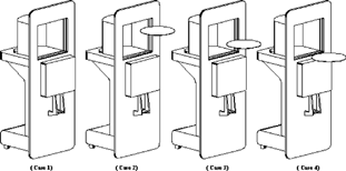
Both measurement and CFD were carried out for the four cases, as summarized in and schematically demonstrated in . Case 1 is selected as a standard case to understand the airflow and particle characteristics when the system is empty. Cases 2–4 represent the situations when the wafer is moved by the robot from the top, middle, and the bottom of the FOUP.
Table 1 Case setup
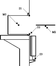
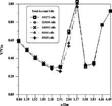
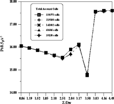
For cases 2–4, the particle generation points (S1, S2, and S3) and particle concentration measuring points M1 (the middle point in the FOUP) and M2 (the backside surface of the wafer) are illustrated in , respectively. The reason for selecting these particular locations is explained here: (1) the impact between FOUP gasket and the minienvironment (process 2) during docking causes particles to be produced on the gasket surfaces such as points S1 (at upper edge) and S2 (at lower edge); and (2) moving parts such as the sliding track of the LPU are contamination sources, where point S3 represents a worst-case scenario at the sliding-track. Particle concentration at points M1 and M2 was measured for each case. A positive pressure differential of 2 Pa between minienvironment and cleanroom was maintained for all cases. As to the particle-tracking simulation, 106 particles (with diameter of 0.2 μ m) were released from each of the source points for each case. The number of particles deposited on both interior surfaces of the FOUP and the wafer were calculated. The grid independence tests of the CFD work were performed for Case 3 using 39150, 68606, 141082, and 219108 tetrahedral cells. The velocity magnitude and pressure at twelve points in the middle section (see ) were tested and compared. Figures and show the grid independence test results for the velocity and pressure. The results from the four different numbers of cells are similar to each other except that at Z/D w = 2.84, which is located in the recirculation area under the wafer. In this location, the percentage difference of predicted data with 141082 and 219108 cells for velocity and pressure are within 1%. Therefore, 141082 cells were chosen for the final runs, which accommodated both computer memory size and running time. The typical real-world computation time for 3850 iterations on a personal computer with Pentium IV with 1.6 GHz CPU and 512 MB memory is about 12 hours.
RESULTS AND DISCUSSION
Airflow Patterns
Even though the study was conducted for a 3D geometry, 2D vectors and streamlines are shown for better presentation. The airflow pattern is expressed in terms of velocity vectors. For comparison and verification, the numbers of predicted velocity vectors are interpolated to fit the numbers of measured velocity vectors, as shown in Figures , , , for Cases 1–4, respectively. In these figures, all physical dimensions are nondimensionalized by the diameter of the wafer (D w ). Predicted streamlines for Cases 1–4 are also presented in order to identify the vortices and to evaluate the contamination risk.
FIG. 9The predicted versus measured velocity vectors for case 1: (a) measured velocity vectors, (b) predicted velocity vectors, and (c) streamtrace placement.
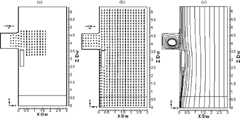
FIG. 10The predicted versus measured velocity vectors for case 2: (a) measured velocity vectors, (b) predicted velocity vectors, and (c) streamtrace placement.
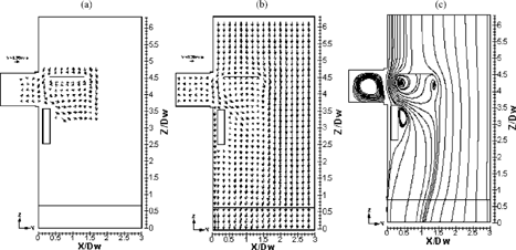
FIG. 11The predicted versus measured velocity vectors for case 3: (a) measured velocity vectors, (b) predicted velocity vectors, and (c) streamtrace placement.
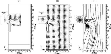
FIG. 12The predicted versus measured velocity vectors for case 4: (a) measured velocity vectors, (b) predicted velocity vectors, and (c) streamtrace placement.
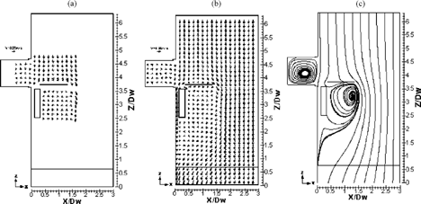
Flow Pattern in Case 1
The flow pattern in Case 1 is very similar to that of a cavity flow, in which a large vortex is formed inside the cavity (in the FOUP, as shown in ). Any particle produced in different positions of the FIM during the docking process is anticipated to be pushed into the FOUP and eventually circulated there. Meanwhile, a separation point is observed in the upper part of the LPU, i.e., FIM, where air is pushed into the FOUP. Particles in this separation area are expected either to transport into the FOUP or to settle on the FIM. Accordingly, after the wafer is brought back into the FOUP, these deposited particles could drop and contaminate the front surface of the wafer below.
Flow Pattern in Case 2
The velocity vectors in Case 2 are shown in . The space between the wafer and the FIM is large. Thus, a large
vortex and a small vortex are present beneath the wafer. According to both measured and predicted vectors, the large vortex has a size of about 1.0 D w in the downstream direction. This vortex extends to the lower part of the FOUP and reaches the FIM. Particles within the vortex can be carried to the back surface of the wafer. This is notable for wafer patterns with dimensions of 0.18 μ m or smaller. Particles on the back surface of the wafer are anticipated to cause contamination problems. When the airflow exceeds the LPU, the third vortex, which extends to about 1.3 D w downstream, is observed.
Flow Pattern in Case 3
The airflow pattern in Case 3 (see ) is similar to that in Case 2. The space between the wafer and the LPU is smaller than that of case 2. Therefore, only one vortex below the wafer is observed. This vortex reaches the LPU. The other vortex on the LPU has about the same size (1.2 D w ) as that in Case 2. However, this vortex is larger (approximately 0.5 D w ) in the lateral direction (x direction) than that in Case 2.
Flow Pattern in Case 4
shows the air velocity vectors in Case 4. The presence of the wafer at this height has a minute impact on the flow pattern near the FOUP, because the position of the wafer is low. Accordingly, the flow pattern above the wafer is similar to that in Case 1 (). However, the space between the wafer and the FIM is small. Thus, the airflow on the back surface of the wafer is almost lateral as determined experimentally and numerically in . Therefore, a single large vortex is eventually produced under the righthand side of the wafer. Notably, the vortex extends to the lower part of the LPU, approximately 1.7 D w downstream below the wafer. In this situation, any particle produced by the moving part of the LPU may be entrained into the vortex and eventually deposited on the back surface of the wafer.
Particle Transport Characteristics
Two approaches were used to assess particle contamination. First, we measure the particle concentration ratio (measured particle concentration divided by the challenge particle concentration) using laser particle counters. Second, we predict the particle deposition ratio (number of particles deposited on wafer divided by the number of particles released) by CFD modeling. displays the predicted deposition ratio on the surfaces of the FOUP and the wafer, as well as the measured concentration ratio at points M1 and M2 in Cases 1 to 4.
Table 2 Predicted deposition ratio versus measured concentration ratio
Measured Particle Concentration Ratio
In Cases 2–4, particles from S1 (the upper edge of the FOUP) are associated with greater contamination ratios on the surfaces of the FOUP and wafer, compared with those from S2 (the lower edge of the FOUP). In Case 4, no particle from S1 was carried down to M2 (the backside of the wafer) because S1 and S2 are located above M2. Notably, particles from S3 were entrained toward M2 with a concentration ratio of 0.0061, which is consistent with the expectations discussed in the preceding section. Fortunately, no particle from S3 was detected at point M1, indicating that the particles produced near the LPU were not induced to the FOUP.
Predicted Particle Deposition Ratio
Deposition Ratio in Case 1
The deposition ratio on the surfaces of the FOUP in Case 1 were high (0.752 and 0.493 from S1 and S2, respectively) because of the vortex that appears inside the FOUP, as shown in .
Deposition Ratio in Case 2
The deposition ratio on the surfaces of the FOUP in case 2 (0.273 and 0.202 for particles from S1 and S2, respectively) is less than that in Case 1. This is due to the airflow in point S2 of this case being away from the FOUP. In comparison, the airflow in Case 1 is towards the FOUP, as shown in . The deposition ratios on the surfaces of the FOUP and on the wafer from S1 (i.e., 0.273 and 0.006, respectively) exceed those from S2 (i.e., 0.202 and 0.001, respectively). Mostly this is because the particles released from S1 were either entrained into the FOUP or the vortices under the wafer, as discussed in the last section. Only 0.1% of particles from S2 were entrained into the wafer. No particles from the S3 deposited on the wafer.
Deposition Ratio in Case 3
The deposition ratio on the surfaces of the FOUP (0.633) was remarkably higher than that of Case 2, while that on the wafer was less than that in Case 2, because the space between the wafer and the top interior surface in this case was greater than that in Case 2. Thus, most of the particles from S1 were pushed into the FOUP rather than deposited on the front side of the wafer. As in Case 2, the deposition ratio on the surfaces of the FOUP and the wafer from S1 exceeded that from S2. No particles from S2 and S3 deposited on the wafer.
Deposition Ratio in Case 4
This is the only case that particles from S3 were entrained into the back surface of the wafer: the deposition ratio was 0.005, consistent with the section of airflow pattern. Therefore, the LPU must be effectively shielded and locally exhausted to mitigate the transportation of particles. The deposition ratios on the surfaces of the FOUP from S1 and S2 were also notably high. Therefore, the wafers in this case were the most easily contaminated.
In general, the predicted particle deposition ratios on the surfaces of FOUP and wafer follow the same trends as the measured concentration ratios at M1 and M2. The predicted deposition ratio of the FOUP surfaces has the same order of magnitude as the measured concentration ratio at M1. The values on the wafer differed by about one order of magnitude. Both approaches yielded approximate contamination ratios on the wafer in Case 4 (measured concentration ratio = 0.006 and predicted deposition ratio = 0.005, differing by about 20%). Both the measured and predicted results demonstrate that particles from S1 are more likely to cause contamination than particles from S2.
Pressure Differential versus Contamination Ingression
A positive pressure differential between the minienvironment and the cleanroom environment must be maintained to keep cleanroom particles from ingression into the minienvironment system. This positive pressure is especially important when there is an air gap between the FOUP and the minienvironment. The pressure differential (dP) between the minienvironment and surrounding environment is affected by several factors. These factors include open ratio of the perforated plate of the minienvironment (βmini), the open ratio of the perforated plate of the cleanroom (βcr), the air change rate of the minienvironment (ACHmini), and the air change rate of the cleanroom (ACHcr). With an air gap of 0.002 m and for practical operational range, the following linear regression equations from additional simulations show the influences of βmini, βcr, ACHmini, and ACHcr on the pressure differential, respectively:
dP = −0.365βmini + 11.0233 (for ACHcr = 250 1/h, ACHmini = 7411 1/h, βcr = 30%)
dP = 0.063βcr−0.906667 (for ACHcr = 2501/h, ACHmini = 7411 1/h, βmini = 30%)
dP = 0.002 ACHmini− 0.725073 (ACHcr = 250 1/h, βcr = 30%, βmini = 30%)
dP = −0.008ACHcr + 1.045 (ACHmini = 7411 1/h, βcr = 30%, βmini = 30%).
FIG. 13(a) Velocity vectors (m/s), (b) pressure contours (Pa), (c) concentration contours (particles/m3) for a slight positive pressure differential case (dP = 0.18 Pa).
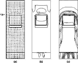
The “slope” values of the above linear regression equations are −0.365, 0.063, 0.002, and −0.008, respectively. The positive slope values (0.063 for βcr and 0.002 for ACHmini) indicate that the pressure differential increases for increasing βcr and ACHmini. Similarly, the negative slope values (−0.365 for βmini and −0.008 for ACHcr) indicate that the pressure differential increases for decreasing βmini and ACHcr. Notably, βmini affects dP almost six (0.365/0.063 = 6.0) times greater than that of βcr. Therefore, the most influential factor affecting the pressure differential is βmini. Another important issue is to determine the required pressure differential value. By assuming that the particle concentrations in the cleanroom and in the supply air of FFU were 1,000 particles/m3 and 0 particles/m3, respectively, and the diffusion coefficient of the concentration was 0.0002 m/s2 (Ljungqvist and Reinmuller 1996), several cases with different positive pressure differentials were carried out to investigate the influences of pressure differential on contamination concentration distribution. shows the velocity vectors, pressure contours, and the concentration contours in the air gap between the FOUP and the minienvironment at a 0.18 Pa pressure difference (pressures in the minienvironment and the clean room
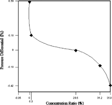
are 0.36 Pa and 0.18 Pa, respectively). In the gap, even the velocity vectors (with the maximum and minimum velocity magnitude of 0.33 m/s and 0.14 m/s, respectively) are outward and the pressure is positive (0.34 Pa); and the value of the concentration is also positive. Note that the concentration decreases from the upper edge (about 100 particles/m3) to the lower edge (2 particles/m3). The lower edge exhibits a low concentration because of the presence of the FOUP stage. indicates the predicted values of the concentration ratio (concentration in the middle point of the FOUP divided by the concentration in the clean room, i.e., 1,000 particles/m3) for different pressure differential situations ranging from −0.42 to 0.59 Pa. A positive pressure differential of 0.59 Pa is required to prevent the FOUP from contamination by cleanroom environment. This positive pressure differential of 0.59 PA is much less than the value (12.7 Pa) suggested by Sherwood et al. (1999). Notably, at slightly over pressure—for example, 0.05 Pa, as indicated in Schneider et al. (1998)—the value of concentration ratio is 0.205.
CONCLUSIONS
In this study we have experimentally and numerically investigated the airflow, particle transportation characteristics, and pressure differentials of a FOUP/LPU minienvironment system. According to the results of this study, we conclude the following:
| 1. | Particles from the upper edge of the FOUP present a greater risk of contamination on the surfaces of the FOUP and the wafer than those from the lower edge of the FOUP. When the wafer is in the bottom position, the vortex reaches the lower part of the moving part of the LPU, and the particles from the LPU are carried to the back surface of the wafer. For particle contamination on the back surface of the wafer in the bottom position, the measured particle concentration ratio differs from the predicted particle deposition by approximately 20%. | ||||
| 2. | The most important factor influencing the variation in pressure differential between minienvironment and clean room is the open ratio of the perforated plate of the minienvironment (βmini). A positive pressure differential of at least 0.59 Pa is required, and a slight positive pressure (for example 0.18 Pa) is not enough to keep the FOUP from ingression of particle contamination. | ||||
NOMENCLATURE
| ACH | = |
air change rate (1/h) |
| C | = |
particle concentration (pts/m3) |
| C μ | = |
turbulent viscosity constant (= 0.09) |
| D w | = |
wafer diameter (300 mm) |
| F b | = |
Brownian force per unit mass (N/kg) |
| F d | = |
drag force per unit mass (N/kg) |
| F e | = |
electrical force per unit mass (N/kg) |
| g | = |
gravitational acceleration (m/s2) |
| k | = |
kinetic energy of turbulence (kg m2/s2) |
| L | = |
hydraulic diameter (m) |
| P | = |
pressure (N/m2) |
| V | = |
mean air velocity (m/s) |
| u i p | = |
instantaneous velocity of the particle (m/s) |
| l | = |
mixing length (m) |
| min | = |
minienvironment |
| u | = |
velocity component in x direction (m/s) |
| v | = |
velocity component in y direction (m/s) |
| w | = |
velocity component in z direction (m/s) |
| x | = |
x direction coordinate |
| y | = |
y direction coordinate |
| z | = |
z direction coordinate |
| C pj | = |
pressure-jump coefficient |
| T L | = |
fluid Lagrangian integral time scale |
| V n | = |
velocity normal to perforated plate (m/s) |
| Greek Symbols | ||
| α | = |
permeability of the perforated plate (m2) |
| β | = |
open ratio of the (%) |
| Δm | = |
thickness of the perforated plate (m) |
| ρ | = |
air density (kg/m3) |
| ζ | = |
a normally distributed random number ranging from 0 to 1 |
| τ e | = |
characteristic lifetime of an eddy |
| μ | = |
molecular viscosity |
| μ e | = |
effective viscosity |
| μ t | = |
turbulent viscosity |
| ϵ | = |
kinetic energy dissipation rate of turbulence (kg m2/s3) |
REFERENCES
- Abu-Zaid , S. Airflow Analysis of Various LPT 2200 Configuration . Proc. of the 43th IES Annual Technical Meeting . 1997 . pp. pp. 139 – 147 . Institute of Environment Science .
- Fosnight , W. , Tatro , J. , Shenk , J. and Christie , E. 1998 . “ Asyst Standard Mechanical Interface Indexer (SMIF-INX) 2200 Evaluation, Technology Transfer #98053510A-TR ” . Austin, TX : International SEMAECH .
- FLUENT . 1998 . Fluent 5 User's Guide , Vol. 2 and 3 , Lebanon NH, , USA : Fluent Inc. . 03766
- I3001 . 1996 . “ I300I 300 mm Equipment Performance Metrics ” . Austin, TX : International SEMATECH .
- Kobayashi , Y. , Kobayashi , S. , Tokunaga , K. , Kato , K. and Minami , T. 2000 . Particle Characteristics of 300-mm Minienvironment (FOUP and LPU) . IEEE Trans. Semiconduct. Manufact , 13 ( 3 ) : 259 – 263 . [CSA]
- Ljungqvist , B. and Reinmuller , B. 1996 . Clean Room Design , Buffalo Grove, IL : Interpharm Press, Inc. .
- Liu , B. and Yoo , S. 1996 . Isolation Ratio and Particle Performance Measurement of a SMIF System . Proceedings of the Institute of Environmental Sciences and Technology . 1996 , Mount Prospect, IL. pp. p. 456
- Patankar , S. V. 1980 . Numerical Heat Transfer and Fluid Flow , p. 59 New York : Hemisphere Publishing Corporation, Hemisphere Publication Company . Chapter 6
- Rodi , W. 1980 . Turbulence Models and Their Applications—A State of the Art Review , Delft, The Netherlands : AHR .
- Schneider , H. , Fabian , R. , Sczepen , R. , Hollemann , H. and Honold , A. 1998 . Air Flow Modeling and Testing of 300 mm Minienvironment/Load Port System . Proc. 44th IES Annual Technical Meeting, Institute of Environment Science . 1998 , Phoenix, AZ. pp. pp. 411 – 418 .
- Sherwood , E. , Hope , D. , Whitmore , J. , Ottesen , C. and Davis , C. 1999 . Integrated Minienvironment Design Best Practices , Austin, TX : International SEMATECH . Technology Transfer #99033693A-ENG.
