Forming collimated and size–selected particle beams is a necessary component of certain instruments and industrial processes. An ideal aerosol inlet produces particle beams at high efficiency and transmission rate. The particle transmission rate can be maximized by slot geometries to generate a tightly focused particle beam that is confined to a desired volume. Traditionally, orifices and capillaries have been employed to generate focused particle beams where particle inertia is used to separate them from the carrier gas. The goal of this work is to improve the current inlet geometries for enhanced transmission of particles. For this purpose, we propose a novel inlet geometry that comprises a series of matched capped slots upstream of a choked orifice inlet. By adjusting the pressure, the geometry transmits an arbitrary particle size with high efficiency while maintaining a high flow rate. The slot dimensions can be analytically determined by constraining the design such that the slots and choked orifice focus the same particle sizes and have the same mass flow rate. Numerical simulations of the flow and particle trajectories through the inlet are carried out using the CFD code FLUENT. The new geometry is found to enhance the focusing characteristics of the orifice while maintaining the high flow throughput. The geometry is further optimized to maximize the transmission rate.
Introduction
Most modern on–line single–particle characterization techniques require the formation of highly focused particle beams. Traditionally, axisymmetric capillaries and orifices have been used to accelerate the flow to sonic conditions, thereby employing particle inertia to separate the particles from the carrier gas. Many researchers have studied the formation of these beams (e.g., CitationDahneke and Friedlander 1970; CitationDahneke and Cheng 1979; CitationFernández de la Mora and Riesco–Chueca 1988; CitationMallina et al. 1999). The particle size range that is focused depends on the particle Stokes number, Stk, which is essentially the ratio of the inertial forces to drag force on the particle. A given geometry operating under prescribed conditions transmits a narrow range of particle diameters (CitationDahneke and Cheng 1979; CitationFernández de la Mora et al. 1996). This optimum particle diameter depends on the inlet geometry and operating conditions through its dependence on the Stokes number, Stk (Dahneke 1982; CitationFernández de la Mora and Riesco–Chueca 1988).
An aerosol inlet plays an important role in producing particle beams at high efficiency and transmission rate. Inlets can be designed in different ways to produce desired beams. For instance, an inlet can be designed to preferentially transmit particles over a specific narrow or wide size range. Thus, the characteristics of particle beams are dependent on the inlet geometry. One of the important requirements of these inlets is to maximize the particle transmission rate, which can be accomplished, for instance, by forming a beam that is completely located within the ionization volume of the mass spectrometer. CitationLiu et al. (1995) developed an inlet design comprising several orifices in series for producing collimated particle beams that transmit a wide particle size range. However, their approach cannot be used to focus a narrow, selectable size range of particles, which is required for chemical characterization of single particles (CitationMallina et al. 2000). Further, as the lenses operate at low pressures, they are limited in the mass flow that can be transmitted. A new inlet geometry made of a choked conical orifice capped by a cone was investigated previously (CitationMiddha and Wexler 2003) for focusing a narrow particle size range. The best geometries in this work were found to yield a tenfold enhancement in transmission rate over the current designs; however, the geometries were limited by the very narrow particle size range focused.
In the current work, we propose a series of matched rectangular slots upstream of a choked orifice. The geometry is similar in concept to the one introduced by CitationLiu et al. (1995a, Citationb) but is able to focus the same particle size range as the choked orifice, thus increasing the size range that is focused, while still enabling the focused size to be selected by adjusting the upstream pressure.
FOCUSING GEOMETRIES
Typically, axisymmetric elements like orifices and capillaries are used to separate particles from the flow streamlines and bring them closer to the axis. These elements employ inertia to focus the particles. The smaller particles (those with Stokes number much less than unity) therefore tend to follow the streamlines not crossing the centerline, whereas the larger ones (those with Stokes number much greater than unity) are less disturbed by the flow, so they cross the centerline. The particles with intermediate inertia are separated from streamlines and focused towards the axis; therefore, particles with certain Stokes numbers are brought to the axis.
Capillaries
An efficient inlet transmits a large fraction of a desired range of particle diameters while maintaining a high flow rate through it. The transmission rate of an inlet is the fraction of particles in the inlet that successfully reach the ionization volume, which depends on the velocity of the particles, area of the source region, mass flow rate, optimum particle diameter, fraction of particles, and the range of particle diameters focused (CitationMiddha and Wexler 2003). Enhancement of a focusing geometry is defined as the increase in particle transmission rate of that geometry over a choked orifice operating under identical conditions. It is a function of the mass flow rate, the nominal Stokes number focused by that geometry, and the range of particle diameters focused. Therefore, an enhancement factor of one means that the geometry does no good over the existing choked orifice geometry, although it does not reduce the transmission rate of the orifice.
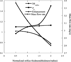
Capillaries have been shown to focus a broader range of particle diameters than orifices (CitationWexler and Johnston 2001). The dependence of various focusing characteristics on orifice/capillary length was studied by numerical simulation. shows that the range of particle diameters focused, which is characterized by the variance of the normal distribution of particle diameters, σg (CitationSeinfeld and Pandis 1998), does increase slightly as the orifice is made longer (i.e., approaches the characteristics of a capillary), but the effect is outweighed in terms of transmission rate by the decrease in the mass flow rate and the increase in Stk orifice . In effect, the overall transmission rate of an orifice decreases as the length is increased. Therefore, choked orifices perform better than capillaries in terms of overall efficiency and transmission rate. Also, capillaries have additional clogging problems, and therefore they cannot be used for long–term studies without frequent maintenance.
Circular Aerodynamic Lenses
CitationLiu et al. (1995a, Citationb) proposed an inlet comprising a series of orifices for focusing a wide range of particle diameters. The lens assembly increases the range of the particle diameters focused by making the beam to pass through successive orifices of decreasing size so that smaller particles get focused progressively. However, this approach is also limited in its transmission rate because it can focus a wide range of particle diameters only at the cost of a decrease in the flow rate of the choked orifice due to the low pressures employed. In addition, Liu and colleagues carefully designed their lens array to function only at a single pressure, whereas in this work we seek a configuration that focuses over a range of pressures, since we wish to use pressure to select the particle size range to analyze (CitationMallina et al. 1999; CitationMiddha and Wexler 2003). This mechanism has also been successfully used for the design of impactors (CitationFernandez de la Mora 1990); different particle size cutpoints have been obtained by simply varying the operating pressure of the instrument.
In the region of high Knudsen number, it is advantageous to vary the nozzle pressure rather than the nozzle diameter for two reasons. Firstly, the Stokes number in this mechanism varies directly as the particle diameter as opposed to the square of the particle diameter in lower Knudsen number range. Thus, the transmission rate is not a strong function of the particle diameter and falls less drastically for particles that are not of the optimum size as compared to the earlier mechanism. Secondly, under choked conditions operation the mass flow rate obtainable with this mechanism is higher than that where the orifice size is varied. The mass flow rate varies linearly as the pressure and varies as the square of the diameter. Therefore, the mass flow rate decreases much faster when the diameter is reduced as compared to the design in which the pressure is reduced.
Slot Aerodynamic Lenses
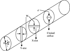
In our previous study (CitationMiddha and Wexler 2003) it was observed that the particles that are initially close to the axis experience smaller radial forces compared to particles that are farther away. They, therefore, tend to remain close to the axis even after the sonic expansion in a choked orifice. Thus, the geometric standard deviation of particles transmitted by an orifice depends on the initial radial position, so that positions closer to the central axis have a larger geometric standard deviation, transmitting more particles, while positions further away from the axis have a smaller one. The efficiency of a choked orifice can therefore be increased by upstream elements that concentrate particles towards the axis. However, there are a number of constraints on the focusing element: (1) it must focus the same nominal particle size as the choked orifice, (2) it must transmit the same mass flow rate as the choked orifice, and (3) it must impose a small pressure drop to keep the mass flow rate high. Slot aerodynamic lenses can satisfy all these requirements (see ). Based on the above considerations, the proposed lens assembly consists of two rectangular slots, spanning the entire diameter of the tube in two mutually orthogonal directions followed by a choked orifice. These two slots will concentrate the particles towards the axis in two orthogonal directions independent of each other. Hence particles entering the choked orifice would be preferentially located in an area close to the axis.
Calculation of the Slot Dimensions
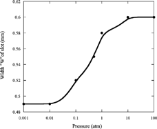
The slot is placed upstream of the orifice to better focus the particles that will be focused by the choked orifice. To ensure the same high mass flow rate through the orifice, the slot dimensions must satisfy (see )
For D2
p,max―orifice
/λ2
sonic
> 1, which corresponds to free molecular regime pressures, EquationEquation (9) reduces to
SOLUTION STRATEGY
To validate the aforementioned enhancement in focusing through the use of straight rectangular slots, commercially available CFD software FLUENT (version 6.0) was used to simulate the fluid flow and the particle motion in a single slot shown. The grid was generated using GAMBIT, a preprocessor tool provided by FLUENT. Only a symmetric quadrant of the geometry was simulated, and a structured quadrilateral mesh was generated for the flow domain. For the normal slots, a full 3D simulation was carried out to show that the results did not differ significantly from a 2D version of the same geometry in terms of particle focusing. A symmetric 2D version of the V–slots was subsequently simulated. The skewness of the mesh elements was maintained below 0.8 in the entire domain, and the aspect ratio of the elements was less than 10. The mesh was made more dense close to the slot to resolve any large gradients in velocities and was made more coarse in the regions with small velocity gradients to improve computational efficiency. The particle trajectory was solved in a Lagrangian frame of reference by integrating the force balance. For submicron particles, a user–defined Stokes law with a linear Cunningham correction factor mentioned earlier was used. The particle was assumed to be spherical and of unit specific gravity. The numerical simulations neglect Brownian diffusion and Saffman lift forces.
RESULTS AND DISCUSSIONS
Normal Slots
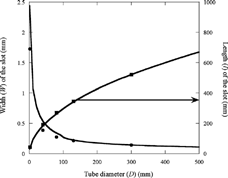
The tube diameter, equal to the slot length, was initially chosen to be 35 mm from our previous study, and the corresponding slot width was then calculated. The flow was subsequently modeled in that geometry. A large recirculation region was observed downstream of the slot. The recirculation was found to decrease with decreasing tube diameter, even though Re based on slot width increases, because as the tube diameter decreases the distance from the slot edge to the wall decreases due to the increase in slot width (see EquationEquation (10)). This results in a smaller recirculation zone. The tube diameter was therefore decreased to scan for an aspect ratio of the slot that minimized the recirculation. The slot dimensions investigated are tabulated in . It was observed from numerical simulations that the thickness of the slot does not affect the focusing significantly, which is similar to the effect of thickness on the focusing orifice, and it was chosen to be 1.6 mm, which is the same as that for the orifice. The slot was then characterized in terms of its particle concentrating capacity. The particles were injected at an axial distance 50 mm upstream of the slot at different radial positions. The trajectories were followed up to an axial distance 50 mm downstream of the slot. It was observed that there was no variation in Stk
slot
and σg
along the length, and thus there is no concentration of particles occurring along the lengthwise dimension of the slot. This affirmed the hypothesis that the slots in two orthogonal directions are uncoupled and concentrate the particles in two orthogonal directions independent of each other.
Table 1 Dimensions (in mm) of the normal and V–slots investigated by this work
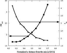
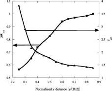
The slot was further characterized in the direction perpendicular to its length. Figures and show the variation in Stk slot and σg perpendicular to the slot length for operating pressures of 0.001 and 0.01 atm, respectively. Notice that for both pressures σg decreases and Stk slot increases as the distance from the axis increases, which is similar in nature to the behavior of a choked orifice observed previously (CitationMiddha and Wexler 2003). Also notice that a larger fraction of particles are focused as the operating pressure is increased, which can be explained by a boundary layer effect similar to the one affecting the characteristics of an orifice (CitationMiddha and Wexler 2003). However, the σg observed was smaller at a higher pressure. This can again be explained on the basis of an increase in recirculation downstream of the slot with the increased Reynolds number, whereby some of the smaller particles are lost. As the operating pressure is increased, the recirculation region increases in size and therefore the particles are lost in it. The slots fail to concentrate the particles towards the centerline beyond an operating pressure of 0.02 atm.
V–Shaped Slots
As discussed above, the focusing capability of normal slots clearly diminishes as pressure increases. For the straight slots, the recirculation sets in at pressures as low as 0.0025 atm. The focused Stokes number becomes much larger and the geometric standard deviation becomes much smaller with increasing pressure. This can be attributed to the recirculation that develops as the pressure increases. This recirculation problem also limits the lens geometry proposed by Liu et al. to low pressures. Recently, CitationGoo (2002) proposed the insertion of spacers in a cascade of slit lenses to reduce recirculation and its tendency to trap particles. Unfortunately, the insertion of spacers leads to a decrease in the mass flow rate and cannot be used for our purpose of maintaining a high throughput.
In our previous work (CitationMiddha and Wexler 2003), we observed better focusing performance for conical lenses than for flat lenses. Therefore, we explored the same V–shaped geometry for slots. This also presents an opportunity to reduce or remove recirculations. In such a divergent flow, the velocity profile is greatly affected by the Reynolds number and the angle of divergence. G. B. CitationJeffrey (1915) and G. CitationHamel (1916) independently investigated the flow through channels with small angles of divergence with the aid of an analytical solution to the Navier–Stokes equation. The solution describes a steady flow of an incompressible, viscous fluid between nonparallel infinite plates, which include an angle of 2α. The continuity equation is satisfied by assuming a radial velocity of the form u = f(θ)/r. Using this in the Navier–Stokes equation expressed in cylindrical coordinates, an ordinary differential equation is obtained for f(θ)
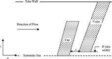
The flow simulation through the V–slot resulted in a stagnation bubble upstream of the slot. To avoid the formation of the stagnation bubble and enhance focusing through the V–slot we explored capping the slot, which has been shown to focus particles significantly better than uncapped geometries (CitationTafreshi et al. 2002; CitationMiddha and Wexler 2003). depicts a 2D symmetric section of the proposed geometry. The width of the slot was calculated assuming that Stk slot for the proposed capped V–slots is about the same as for the capped cone geometries investigated by CitationMiddha and Wexler (2003). The angle of the V–slot was calculated assuming the Jeffrey–Hamel solution and pure outflow for a pressure of 0.25 atmospheres. The angle of the cap was chosen to be larger than that of the slot to minimize boundary layer development because the flow is constantly accelerating. Also, the separation between the slot and cap was larger than the slot width so that the largest accelerations are in the slot, confining particle streamline crossings there. lists the dimensions of the V–slot investigated in this work. Notice that the tube diameter chosen for the V–slot (80 mm) is larger than the tube diameter for the tube containing the orifice; the two tubes can be connected by a slowly converging section, which should further confine the focused particles to a smaller volume close to the axis as they approach the orifice. Further, all the sharp edges were rounded to avoid any pockets of recirculating fluid. summarizes the simulation results for the proposed slots at 0.0025 atm and 0.025 atm. Notice that Stk slot does not vary significantly with pressure. It decreases slightly with increased pressure as the Reynolds number increases; however, the wide range of particle diameters focused through these slots still enable them to be used in conjunction with the orifice at both pressures. Also, notice that Stk slot is much larger than the assumed value of 0.5, which is due to the difference in geometry investigated by this work and the capped cones investigated earlier (CitationMiddha and Wexler 2003).
Table 2 Preliminary focusing characteristics of the V–shaped slots at different pressures
However, the flow does separate in the slots at high pressures, due to differences between the current flow configuration and the assumptions made for the Jeffrey–Hamel flow, primarily that the flow entering the slot is no longer purely radial and has a large positive axial component. In spite of the observed separation at high pressures, the slots can be successfully used to direct a very wide range of particle diameters into the choked orifice at a multitude of pressures, and the capped V–shaped slots can be matched to increase the efficiency of the orifice more effectively than the straight slots, as discussed below.,
Figure 8 Variation of Stk slot with normalized radial distance in capped V–shaped slots at different operating pressures.
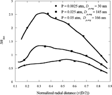
Figure 9 Variation of σg with normalized radial distance in capped V–shaped slots at different operating pressures.
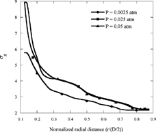
It should be noted that both normal slots and the capped V–slots perform very well at low pressures and can be used in conjunction with a choked orifice to focus particles. However, the normal slots lead to recirculation in the flow at a much lower pressure (∼0.0025 atm), whereas the problem is delayed to about 0.05 atm in capped V–slots. Also, the recirculation becomes large enough to hinder focusing by normal slots at 0.02 atm, whereas recirculation does not affect the focusing adversely up to 0.1 atm in the case of capped V–slots. The characteristics of the normal slots and capped V–slots are similar; the Stk slot decreases as the operating pressure is increased. However, the σg for the capped V–slots (∼4.5) at a pressure of 0.05 atm is much larger than that for normal slots (∼2) at their maximum operating pressure (0.01 atm) and can be used to match the particle diameters focused by the choked orifice. Therefore, the capped V–slots are much more robust when it comes to handling the recirculation in the flow and can be used for a much wider range of pressures to size select the particles.
The slot dimensions were then corrected by taking the actual focusing characteristics of the capped V–slots into account. Figures and represent the focusing characteristics of the matched V–slots in terms of Stk slot and σg at pressures of 0.0025, 0.025, and 0.05 atm. The focusing characteristics are similar to those of orifices or straight slots. The optimum Stokes number decreases and σg increases as the pressure is increased. The effect of the variation in Stk slot with pressure is outweighed by the increased σg , so the capped V–slot matches the choked orifice over a wide pressure range. Although separation sets in at 0.05 atm, the slots still focus a wide range of particle diameters. For operating pressures above 0.1 atm, separation dominates the flow and adversely affects the focusing of particles, reducing overall particle focusing efficiency.
Note also that the pressure drop across the orifice increases with decreasing operating pressure, so that the pressure drop across the slot becomes a significant fraction of the total pressure, thus altering the focusing characteristics of the choked orifice. Furthermore, we need two slots mutually perpendicular to each other so that the pressure drop from the first slot changes the focusing characteristics of the second one.
Considering the aforementioned design constraints, the geometry was further optimized. It was found that focusing is independent of the cap angle and the cap length, and only the slot–cap spacing, s, significantly changed the focusing characteristics of the slot. summarizes these focusing characteristics for various cap–cone spacing at 0.0025 and 0.05 atmospheric pressures, respectively. It was found that at lower pressures Stk slot increases but the focused particle diameter range decreases as the spacing is increased, which is similar to the trend observed for the capped–cone geometries (CitationMiddha and Wexler 2003). These results are somewhat offset at 0.05 atm, which can be attributed to separation at high pressures. A smaller spacing was observed to perform better than larger spacing irrespective of the operating pressure. However, the minimum spacing is limited since it cannot be smaller than the slot width.
Variation of focusing characteristics of V–shaped capped slots with the cap–slot spacing at 0.0025 and 0.05 atmospheres
CONCLUSIONS
The goal of this work was to design an improvement over the current inlet geometries for enhanced transmission of particles. It was shown that the capillaries were not optimal because they reduce the mass flow rate, increase the Stk significantly, and suffer from clogging. The CitationLiu et al. (1995) lens system cannot be used because it has only one parameter and cannot focus a wide range of particle diameters while maintaining a high mass flow rate. A model comprising two rectangular slots followed by a choked orifice was proposed. The slot dimensions were then analytically determined by constraining the design to concentrate a wider range of particle diameters at a high mass flow rate matched to the focusing characteristics of the downstream choked orifice. It was further shown that the slots could be used for a wide range of operating pressures. The flow through the normal slots was simulated and their particle–focusing characteristics were subsequently studied. They were found to focus a very wide range of particle diameters, hence enhancing the particle concentration through the orifice at low pressures. However, at high pressures the normal slots were limited by a large fluid recirculation that hindered particle focusing, rendering them useless. To overcome this, V–shaped slots were investigated, and these slots possess the advantages of the normal slots but are less susceptible to recirculation owing to the gradual increase in cross section. The V–shaped slots were capped to accelerate particles entering the slot and to reduce the boundary layer effect and enhance focusing as observed in our previous work (CitationMiddha and Wexler 2003). The width of the slots was determined in the same manner as for the normal slots; the angle of the V–slot was determined from Jeffrey–Hamel solutions, assuming no backflow at a pressure of 0.25 atm. The V–slots were then characterized in terms of their particle–focusing capabilities. Furthermore, Stk slot was determined and used to correct for the width of the slots. The slots were seen to focus a wide range of particle diameters and therefore, despite the variation in Stk slot with pressure, these slots can be used in conjunction with the orifice for particle concentration at a multitude of pressures. It was found that at pressures greater than 0.1 atm recirculation becomes huge and interferes with the particle–focusing mechanism. However, it is quite remarkable that a fixed–slot geometry can be used over pressures ranging from 0.0025 up to 0.1 atm to focus particles ranging from 10 to 500 nm, respectively. The geometry was further optimized to account for changes in Stk slot and σg with pressure drop. It was observed that the only parameter that affects the focusing is the cap to slot distance. A smaller spacing was observed to perform better than a larger one but it is limited by the width of the slot.
Acknowledgments
This work was supported by the EPA supersite programs via funding to the Pittsburgh and Baltimore supersites.
REFERENCES
- Dahneke , B. E. and Friedlander , S. K. 1970 . Size Separation of Aerosol Beam Particles . J. Aerosol Sci. , 1 : 325 – 339 .
- Dahneke , B. 1973 . Aerosol Beam Spectroscopy . Nature Physical Sci. , 244 : 54 – 55 .
- Dahneke , B. E. and Cheng , Y. S. 1979 . Properties of Continuum Source Particle Beams. I. Calculation Methods and Results . J. Aerosol Sci. , 10 : 257 – 274 . [CROSSREF]
- Fernández de la Mora , J. and Riesco-Chueca , P. 1988 . Aerodynamic Focusing of Particles in a Carrier Gas . J. Fluid Mech. , 195 : 1 – 21 .
- Fernández de la Mora , J. , Nagaraja , R. and McMurry , P. H. 1990b . Inertial Impaction of Fine Particles at Moderate Reynolds Number and in the Transonic Regime with a Thin-plate Orifice . J. Aerosol Sci. , 21 : 889 – 909 . [CROSSREF]
- Fernández de la Mora , J. 1996 . Drastic Improvement of the Resolution of Aerosol Size Spectrometers via Aerodynamic Focusing: The Case of Variable-pressure Impactors . Chem. Egg Comm. , 151 : 101 – 124 .
- Fluent , J. 1998 . Users Manual . J. Fluent Inc ,
- Goo , J. 2002 . Numerical Simulation of Aerosol Concentration at Atmospheric Pressure by a Cascade of Aerodynamic Slit Lenses . J Aerosol Sci. , 33 : 1493 – 1507 . [CROSSREF] [CSA]
- Hamel , G. 1916 . Spiralförmige Bewegung zäher Flussigkeiten . Jahresber. der. Deutschen. Mathematiker-Vereinigung , 25 : 34 – 60 . [CSA]
- Jeffrey , G. B. 1915 . Steady Motions of a Viscous Fluid . Phil. Mag. , 29 : 455 – 465 .
- Liu , P. , Ziemann , P. J. and Kittelson , D. B. 1995a . Generating Particle Beams of Controlled Dimensions and Divergence: I. Theory of Particle Motion in Aerodynamic Lenses and Nozzle Expansions . Aerosol Sci. Technol. , 22 : 293 – 313 .
- Liu , P. , Ziemann , P. J. , Kittelson , D. B. and McMurry , P. H. 1995b . Generating Particle Beams of Controlled Dimensions and Divergence: II. Experimental Evaluation of Particle Motion in Aerodynamic Lenses and Nozzle Expansions . Aerosol Sci. Technol. , 22 : 314 – 324 .
- Mallina , R. V. , Wexler , A. S. and Johnston , M. V. 1999 . High-speed Particle Beam Generation: Simple Focusing Mechanisms . J. Aerosol Sci. , 30 : 719 – 738 . [CROSSREF] [CSA]
- Mallina , R. V. , Rhoads , K. P. and Johnston , M. V. 2000 . High Speed Particle Beam Generation: A Dynamic Focusing Mechanism for Selecting Ultrafine Particles . Aerosol Sci. Technol. , 33 : 87 – 104 . [CROSSREF]
- Middha , P. and Wexler , A. S. 2003 . Particle Focusing Characteristics of Sonic Jets . Aerosol Sci. Technol. , 37 : 907 – 915 . [CROSSREF] [CSA]
- Rosenhead , L. 1940 . The Steady Two-dimensional Radial Flow of Viscous Fluid between Two Inclined Plane Walls . Proc. R. Soc. , 175 : 436 – 467 .
- Seinfeld , J. H. 1986 . “ Atmospheric Chemistry and Physics of Air pollution ” . New York, NY : J. Wiley .
- Seinfeld , J. H. and Pandis , S. N. 1998 . “ Atmospheric Chemistry and Physics: From Air Pollution to Climate Change ” . New York, NY : J. Wiley .
- Wexler , A. S. and Johnston , M. V. 2001 . “ Real Time Single Particle Analysis ” . In Aerosol Measurement: Principles, Techniques and Applications , Edited by: Willeke , K. and Baron , P. A. New York, NY : J. Wiley .
- Tafreshi , H. V. , Benedek , G. , Piseri , P. , Vinati , S. , Barborini , E. and Milani , P. 2002 . A Simple Nozzle Configuration for the Production of Low Divergence Supersonic Cluster Beam by Aerodynamic Focusing . Aerosol Sci. Technol. , 36 : 593 – 606 . [CROSSREF]
- Willeke , K. 1976 . Temperature Dependence of Particle Slip in a Gaseous Medium . J. Aerosol Sci. , 7 : 381 – 387 . [CROSSREF]
