Response functions of the ELPI impactor with normal and porous substrates are presented together with fit functions to describe particle collection. In addition to primary collection efficiency, fits for the secondary collection mechanisms, diffusion, image charge force, and space charge field are presented. Charging efficiency for different configurations is also presented. Presented response functions can be used in data reduction and inversion of ELPI data.
INTRODUCTION
Electrical Low Pressure impactor (ELPI; CitationKeskinen et al. 1992) combines electrical detection with a conventional cascade impactor to acquire real-time aerosol measurement. Since the introduction of the ELPI, it has been used in a wide variety of applications, including radioactive aerosols, pharmaceutical applications (e.g., Crampton et al. 2004; Glover and Chan 2004), combustion studies (e.g., Kymäläinen et al. 1996; Latva-Somppi et al. 1998; CitationHayes et al. 2004), ambient air quality studies, and atmospheric aerosol studies (e.g., Shi et al. 1999; Temesi et al. 2001). Because of the real-time measurement capability of the ELPI, it has seen wide use in automotive emission measurements, both in the industry and in universities and institutes (e.g., Ahlvik et al. 1998; Maricq et al. 1999; Maricq et al. 2000; Ntziachristos and Samaras 2000; van Gulijk et al. 2003).
In ELPI, particles are first charged in a unipolar (diffusion) charger and then classified to size fractions by a cascade impactor. Particle detection is based on the particle charge by measuring the currents generated by collected particles. Therefore, the response functions of the ELPI consist of the efficiency of the charger and collection efficiency of the impactor. There are four main ways to use the ELPI. The impactor can be assembled with or without the electrical filter stage, which is associated with different charger operation parameters. In addition, the impactor stages may have smooth or porous collection plates. The response functions for each case are different.
The charger efficiency functions without the filter stage were presented by CitationMarjamäki et al. (2000) and with the filter stage by CitationMarjamäki et al. (2002). The primary collection efficiency curves of the ELPI-impactor with normal substrates have been presented by CitationMarjamäki et al. (2000). In addition to impaction, there are secondary collection mechanisms in the impactor that are responsible for the “tails” of the collection efficiency curves. These mechanisms have been studied by CitationVirtanen et al. (2001). Marjamäki and Keskinen (2004a, b) studied the effect of collection substrate porosity and roughness on the collection efficiency characteristics of the low cut-point impactor stages of ELPI. They noted that the difference caused by porous plates is so large that the impactor must be re-calibrated. In this paper we present calibration results of the collection characteristics of the ELPI impactor with porous collection plates.
The main aim of this study is to present the response functions of the ELPI in a form that is suitable for data reduction and inversion. For this purpose we review the previous results and present new results for the porous substrates. We present the response functions for the different ELPI configurations in a functional form. Detailed numerical values of the functions are needed when applying inversion algorithms to obtain size distribution.
Impactor Collection Characteristics with Porous Plates
Impactors are characterized by their collection efficiency. Collection efficiency function for each stage i, E i , can be described as a continuous function of particle size describing the fraction of particles collected by the stage. We use the data measured for earlier papers (CitationMarjamäki and Keskinen 2004a, b) to construct the low-concentration collection efficiency curves for the six lowest impactor stages. The higher cut-point stages were calibrated with the methodology presented by CitationMarjamäki et al. (2000) and CitationVirtanen et al. (2001).
Primary Particle Collection Efficiency
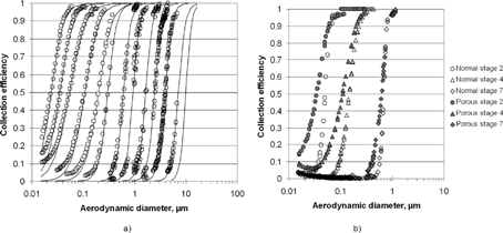
In the ELPI there are 13 impactor stages. Stages are numbered so that the stage with the lowest cut-point is stage 1 and the stage with the highest cut-point is stage 13. Stage 13 is used as a pre-cut and no signal is measured from it, it only acts as upper limit for the impactor. If the electrical filter stage (CitationMarjamäki et al. 2002) is used, stage 12 is removed from the impactor and size range of stage 11 is increased. The primary collection takes place on the impactor plates below the nozzles. The measured collection efficiency curves for stages 1–12 are shown in . compares collection efficiency curves of individual stages with smooth and porous collection plates. As discussed by Marjamäki and Keskinen (2004a, b) the collection efficiency curves are less steep and have a lower cut-point when porous plates are used. However, the difference gets smaller for stages with higher cut point. For stages 8 and above, the difference in cut point is negligible.
Figure 1 (a) Measured and fitted functions for the collection efficiencies of the ELPI-impactor with 40 μ m porous substrates. Measured values shown with circles, and lines represent the fit functions. (b) Collection efficiencies of stages 2, 4, and 7 with 40 μm porous substrates and normal substrates.
Secondary Particle Collection Efficiency
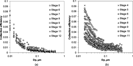
There are several mechanisms that can contribute to the deposition of particles smaller than the cut size of the impactor. Collection caused by these mechanisms takes place not only on the collection plate but also on the stage hull. At low aerosol concentrations the dominant deposition mechanisms are diffusion and deposition caused by the electrical image force. In most cases diffusion is more relevant of these two, image charge deposition is significant to particles larger than 0.2 μ m. Experimental results for the combined effect of diffusion and image charge deposition can be seen in . presents the results for smooth collection plates and presents the results for the porous collection plates. The porous plates cause a much higher level of secondary particle collection efficiency. This is partly explained by changes in the flow characteristics near the collection plate. However, there is also an effect caused by the fact that part of the flow penetrates the substrate and gets filtered by the porous substate material it passes (CitationHuang et al. 2001; CitationMarjamäki and Keskinen 2004a, b).
Construction of the Response Functions
Impactor Collection Efficiency Functions
We use a simple fit function for the primary collection efficiency already described by CitationWinklmayr et al. (1990) and CitationDzubay and Hasan (1990). This was also used by CitationDong et al. (2004) to produce fit functions for the primary collection efficiency E p , obtained by fitting curves to the graphs published by CitationMarjamäki et al. (2000).
where D p,50 is the cutpoint diameter and s is a parameter affecting the steepness of the collection efficiency curve. For the electrical filter stage collection efficiency is assumed to be 1. The same functional form is used both for smooth and porous collection plates ().
Fit curves and measured efficiencies are different at low efficiencies because the fits for the primary collection do not include the effects of secondary collection mechanisms: diffusion, image charge, and space charge. The collection efficiency E D caused by diffusion depends on the diffusion coefficient of the particles and the geometry and flow conditions of the impactor stage in question. Deposition takes place both on the collection plate and the rest of the stage. The flow geometry is therefore a complex mix of planar, tubular, and annular components. For simplicity, a fit based on tube flow geometry was used for the diffusive part:
For image charge the deposition velocity is proportional to the product of the square of the charge and mechanical mobility of the particle. With these assumptions collection efficiency, E IM , can be estimated to be:
When the measured concentration is high, the repulsive electric field generated by the charged particles becomes significant. Particle properties affecting space charge deposition are particle concentration, particle charge, and electrical mobility of the particles. Space charge collection efficiency, E i SC , for stage i can be estimated using the following equation (CitationVirtanen et al. 2001).
When using porous collection plates, secondary collection is enhanced by change of flow conditions near the plate surface, increasing both diffusion and image charge collection efficiency terms. In addition, part of the jet flow penetrates the porous plate. Particles within that part of the flow get filtered by the porous plate material, with varying efficiency. In practice it is rather difficult to estimate the effect of this mechanism or to separate it from the other collection efficiency mechanisms. Therefore the increased collection efficiency of porous plates is treated as if caused by increased diffusion and image charge deposition.
To obtain overall collection efficiency values, the collection processes described above are assumed to be independent and penetration of particles the product of the penetration values of the different processes. Therefore, overall collection efficiency E i for stage i can be calculated from the primary collection efficiency (Equation Equation1), diffusion and image charge deposition (Equations Equation2 and Equation3), and space charge deposition (Equation Equation4)
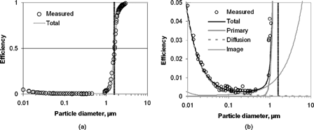
The parameter values of Equations Equation1, Equation2, Equation3, Equation4 were fitted to produce best agreement of Equation Equation5 and the measured collection efficiency values. shows the contribution of primary collection, diffusion, and image charge deposition to the overall collection efficiency of stage 9. There is an increase in deposition for large particles caused by the image charge part of the fit, but in practice it is always lost in the steep rise of the collection curve by impaction. Values for stages 1–4 have to be approximated, because the tail caused by secondary mechanisms cannot be separated from the primary collection efficiency. However the fit using the approximations fits the measured collection efficiencies well.
Figure 3 Measured efficiencies (marked with circles) and fitted functions (marked with lines) for stage 9: (a) Whole collection efficiency curve, fit labeled as total is calculated with Equation Equation5. (b) same collection efficiency with different y-axis and additional curves showing the contribution of primary, diffusion and image charge depositions (calculated with the Equations Equation1, Equation2, and Equation3 with the constants from ). Cut point of the stage shown in both figures with dotted vertical line. (Adapted from CitationMarjamäki 2003).
The fitted values for steepness (s) effective length (L), image charge deposition intensity (c), and residence time (t) for each stage are listed in . Using the constants from , deposition for each stage as a function of particle size can be calculated. Values can be adapted for other ELPI-impactor units with differing cutpoints by changing the corresponding D p,50 value. In the case of porous collection plates we have given a constant C p that can be used to estimate the cutpoint if calibration data is unavailable:
Table 1 Fitted values used in Equation Equation1 for the primary collection efficiency curve. Values for normal and 40 μ m porous substrates
Charging Efficiency
The ELPI is based on the electrical measurement of the collected particles. This means that, in addition to the collection efficiency of the impactor, efficiency of the charger has to be known. ELPI charger has two operation modes, one with the trap voltage (400 V) on and one without the trap voltage. Usually trap voltage is switched off when using the electrical filter stage to allow the passing of smallest particles into the impactor.
The efficiency of the charger is needed to convert the measured currents to number concentrations. Number concentration, C, can be calculated from the currents with the following equation
Response Functions
Impactor Kernel Functions
Impactor response functions are usually labeled as kernel functions. In this paper we use kernel functions to describe the impactor response functions. Response functions are used to describe the overall response functions that include the response functions of both the charger and the impactor.
Kernel functions inform how particles are distributed among each impactor channel. The sum of kernel functions at each particle size is one. Kernel functions, k i , are functions of the particle size and can be calculated from the collection efficiency functions by:
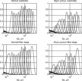
Kernel functions of the ELPI impactor for the different configurations are shown in . Results are calculated assuming unit density particles. Deposition caused by the space charge is evaluated to be zero, that is, aerosol concentration is assumed to be low. Compared to normal smooth substrates, kernel functions with porous substrates are wider, lower, and have more overlap between stages. With the filter stage, kernel function of stage 11 is wider because stage 12 has been removed. The kernel function of the filter stage has similar shape to impactor kernels, because secondary collection in impactor stages increases with decreasing particle size. Since secondary collection is a function of the mobility size of the particles, the kernel of filter stage has a strong dependence on the effective density of particles. This can cause problems especially when measuring particles of unknown composition and density. In the case of normal substrates, filter stage's kernel is wide. As described in CitationMarjamäki et al. (2002), this is problematic when using cut diameter concept for converting the measured currents to number concentrations.
Figure 4 ELPI-impactor kernel functions, k i , of the in different configurations. Functions are calculated according to Equation Equation10 from the collection efficiencies.
ELPI Response Functions for Moment Distributions
Size distribution functions can be presented as a moment distribution linked to the number size distribution f(D p ) by
The ideal response of each ELPI channel is calculated by integrating the product of the charger efficiency E ch(D p ), the impactor kernel function k i (D p ), and the number size distribution f(D p ).
Using Equations Equation11 and Equation12, this can be written for any moment distribution β as:
This means that for moment β, ELPI overall kernel function K β(D p ) = k(D p )D p 1.5 − β.
The type of integral equation in Equations Equation13 and Equation14 is called the Fredholm integral equation of the first kind. Solving this equation for size distribution in not unambiguous, and the procedure is called inversion. The inversion of ELPI data can be made to return different moment distributions. From Equation Equation12 it is obvious that inversion into moment β = 1.5 is similar to inversion of gravimetric impactor data. The two most widely used distributions are the number distribution (i.e., zeroth moment) and the mass distribution, the third moment. Response functions for all of these cases are shown in .
Figure 5 Response functions K β of the ELPI with filter stage and normal collection substrates for different moments: (a) 0-moment (number), (b) 1.5-moment, and (c) 3-moment (volume and mass). Response functions are the combination of the charger response and impactor kernels. Note that the y-axis is logarithmic and in arbitrary units.
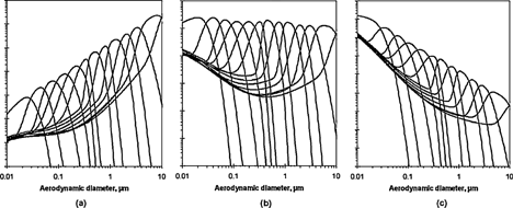
Response functions for moment 1.5 are most even and therefore it would be most natural to use them in inversion (i.e., 1.5th moment distribution, β = 1.5). For the zeroth-moment (number size distribution) and 3rd-moment (mass and volume distribution) there are large differences in the magnitude of the response for different stages. For the 3rd-moment there is also duality in the response functions, that is, high values for both small and large particles, that can make the inversion difficult.
DISCUSSION
Impactor kernels are very similar to the ones reported by other authors for multijet cascade impactors. However the data reduction of ELPI differs significantly from the cascade impactor data reduction because the charging efficiency has to be considered. This gives the response functions a unique shape and makes the data reduction more challenging.
The most important phenomenon not included in this study is probably the particle bounce. As in all impactor measurements, this might cause a substantial error. The bounce can be reduced by using greased impaction plates, which is the standard procedure. In cases where the particle bounce is a particularly severe problem, the porous collection plates need to be used and therefore their response functions are also given.
Another ELPI-related phenomenon not included in this study is the induced currents caused by the rapid changes in aerosol concentration (CitationMarjamäki et al. 1995). If the aerosol concentration—rapidly changes inside the impactor stage this induces a current that is proportional to the time derivative of the charge concentration. When the concentration increases it induces a positive current and when it decreases it induces a negative current. Total time integral of these induced currents is zero but they can be a significant source of uncertainty when studying rapidly changing concentrations in real time.
The particle charging, diffusion and the image charge deposition are parameters that depend on the particle mobility diameter. However, the primary collection efficiency depends on the aerodynamic diameter of the particle. Therefore to get exact results particle effective density has to be known or at least estimated. Fits for the response functions are semi-empirical and they are not supposed to be exactly correct, but they can be used to generate ELPI response functions for aerosols having variable effective densities.
SUMMARY
Response functions for the charger and impactor in different configurations have been presented. The overall response function of the ELPI is the product of the impactor kernels and the charger efficiency. Presented collection efficiency functions for the ELPI-impactor include the primary particle collection caused by impaction and secondary collection caused by diffusion and image charge. Charging efficiency is given in two different trap voltages. Presented equations allow construction of the ELPI response functions for different particle densities. These response functions can be used to develop algorithms for the inversion of ELPI data. A study of the inversion of the ELPI data and an example of an inversion algorithm for the ELPI is presented in the second part of this paper.
REFERENCES
- Dong , Y. , Hays , M. D. , Smith , N. D. and Kinsey , J. S. 2004 . Inverting Cascade Impactor data for Size-Resolved Characterization of Fine Particulate Source Emissions . J. Aerosol Sci. , 35 : 1497 – 1512 .
- Dzubay , T. G. and Hasan , H. 1990 . Fitting Multimodal Lognormal Size Distributions to Cascade Impactor Data . Aerosol Sci. Technol. , 13 : 144 – 150 .
- Huang , C.-H. , Tsai , C.-J. and Shih , T.-S. 2001 . Particle Collection Efficiency of An Inertial Impactor with Porous Metal Substrates . J. Aerosol Sci. , 32 : 1035 – 1044 . [CROSSREF]
- Keskinen , J. , Pietarinen , K. and Lehtimäki , M. 1992 . Electrical Low Pressure Impactor . J. Aerosol Sci , 23 : 353 [CROSSREF]
- Marjamäki , M. , Moisio , M. , Pietarinen , K. , Keskinen , J. , Kymäläinen , M. , Janka , K. , Backman , R. and Hupa , M. 1995 . Fast Size Distribution Measurement System for Combustion and Pyrolysis Experiments . J. Aerosol Sci. , 26 : s105 – s106 . presented at European Aerosol Conference, September 18–22 Helsinki.[CROSSREF]
- Marjamäki , M. , Keskinen , J. , Chen , D.-R. and Pui , D. Y. H. 2000 . Performance Evaluation of the Electrical Low Pressure Impactor (ELPI) . J. Aerosol Sci. , 31 : 249 – 261 . [CSA] [CROSSREF]
- Marjamäki , M. , Ntziachristos , L. , Virtanen , A. , Ristimäki , J. , Keskinen , J. , Moisio , M. , Palonen , M. and Lappi , M. 2002 . Electrical Filter Stage for the ELPI . SAE paper 2002-01-0055
- Marjamäki , M. 2003 . “ Electrical Low Pressure Impactor: Modifications and Particle Collection Characteristics ” . Ph.D. thesis. Tampere University of Technology publications 449
- Marjamäki , M. and Keskinen , J. 2004a . Effect of Impaction Plate Roughness and Porosity on Collection Efficiency . J. Aerosol Sci. , 35 : 301 – 308 . [CROSSREF]
- Marjamäki , M. and Keskinen , J. 2004b . Technical Note: Estimation of the Cutpoint of an Impactor with Porous Substrates . J. Aerosol Sci. , 35 : 657 – 663 . [CROSSREF]
- Virtanen , A. , Marjamäki , M. , Ristimäki , J. and Keskinen , J. 2001 . Fine Particle Losses in Electrical Low Pressure Impactor . J. Aerosol Sci. , 32 : 389 – 401 . [CSA] [CROSSREF]
- Willeke , K. and Baron , P. A. 1993 . Aerosol Measurement: Principles, Techniques and Applications , New York : Van Nostrand Reinhold .
- Winklmayer , W. , Wang , H.-C. and John , W. 1990 . Adaptation of the Twomey Algorithm to the Inversion of Cascade Impactor Data . Aerosol. Sci. Technol. , 13 : 322 – 331 .
