Abstract
Introduction. Free-breathing stereotactic radiotherapy for lung malignancies requires reliable prediction of respiratory motion and accurate target localization. A protocol was adopted for reproducibility and reduction of respiratory motion and for target localization by CBCT image guidance. Tumor respiratory displacements and tumor positioning errors relative to bony anatomy alignment are analyzed. Materials and method. Image guided SRT was performed for 99 lung malignancies. Two groups of patients were considered: group A did not perform any breathing control; group B controlled visually their respiratory cycle and volumes on an Active Breathing Coordinator (ABC) monitor during the acquisition of simulation CT and CBCT, and treatment delivery. GTV on end inhale and exhale CT data sets were fused in an ITV and the extent of tumor motion evaluated between these 2 phases. A pre-treatment CBCT was acquired and aligned to the reference CT using bony anatomy; for tumor positioning the ITV contour on the reference CT was matched to the visible tumor on CBCT. Interobserver variability of tumor positioning was evaluated. ITV and CBCT tumor dimensions were compared. Results. 3D tumor breathing displacement (mean±SD) was significantly higher for group A (14.7±9.9 mm) than for group B (4.7±3.1 mm). The detected differences between tumor and bony structure alignment below 3 mm were 68% for group B and 45% for group A, reaching statistical significance. Interobserver variability was 1.7±1.1 mm (mean±SD). Dimensions of tumor image on CBCT were consistent with ITV dimensions for group B (max difference 14%). Conclusions. The adopted protocol seems effective in reducing respiratory internal movements and margin. Tumor positioning errors relative to bony anatomy are also reduced. However bony anatomy as a surrogate of the target may still lead to some relevant positioning errors. Target visualization on CBCT is essential for an accurate localization in lung SRT.
Target localization in stereotactic radiotherapy (SRT) of intrapulmonary lesions is of major importance for the efficacy of these treatments: high doses are delivered in few fractions and errors on target positioning are often unrecoverable. Historically stereotactic body radiotherapy (SBRT) relied on a rigid and non-invasive external frame, which establishes a stereotactic reference system for patient setup and target localization Citation[1–4]. This approach assumes a fixed relationship between a system of external coordinates and the target volume, but the lack of sharp fixation in SBRT setup may result in inter-fraction and intra-fraction positioning uncertainty since patient movements respect to the SBF are possible Citation[5], Citation[6]. In addition, internal targets are mobile within a patient body and, especially tumors in the thorax are subject to intrafractional respiratory motion. More recently in-room image guidance systems, that yield volume imaging and sufficient soft-tissue contrast have permitted daily imaging of bony anatomy and target permitting online correction of tumor position prior to treatment delivery Citation[4–10], thus eliminating the need of a SBF based setup Citation[8], Citation[10]. However image guided on-line corrections do not eliminate the necessity to address respiratory motion. Conventionally respiratory displacement was accounted for using large margins which were site-specific but not patient specific (population-based tumor motion values are used to create the internal target volume ITV), which could result in either underdosing the target or overexposing healthy tissues Citation[11]. A more accurate approach was that of creating a patient specific ITV, using delineation on CT scans acquired in end inhale and exhale breath-holding Citation[4], Citation[6]. However, the simple acquisition of the CT scans at the end of the inspiration and expiration phase might not be sufficient to guarantee a reliable modeling of the effective internal motion during free breathing irradiation, without a check on the stability and reproducibility of the respiratory cycle. Recently four-dimensional (4D) CT Citation[12] has provided a reliable tool to study patient specific motion without any breath-hold, although using this information to create a complete 4D treatment plan may be time-consuming Citation[12]. However, it must be noted that, even using 4DCT, significant uncertainty may arise from inter and intra-fraction variation of the breathing pattern, as well as variations between imaging and treatment session. Other methods address the problem of reducing the effect of breathing motion during treatment delivery Citation[13], and they include breath-holding technique and respiration gated radiotherapy. Breath-hold techniques are often poorly tolerated by patients with lung cancer and increase substantially the time required for treatment. Respiratory-gated radiotherapy may be associated with uncertainty because of poor correlation of respiratory signal obtained on the patients’ chest with respect to tumor motion Citation[13]. More recently the use of 4DCT for planning in conjunction with respiration correlated 4DCBCT for IGRT has been proposed Citation[7], Citation[14]. This method is surely promising but issues such as the use of different surrogates in planning CT respect to CBCT must be addressed Citation[7].
This article reports our approaches for free breathing image guided lung SRT. Two issues are addressed in detail: first, the necessity of creating a reliable patient specific and reduced ITV which is a good representation of the tumor respiratory excursion during free breathing CBCT acquisition and treatment delivery; second, the reliability of alignment on bony structure as a surrogate for target positioning checked by matching the free breathing CBCT tumor image with the planning ITV contour.
Material and methods
Patients and immobilization
Between January 2007 and April 2008, 71 patients with 99 lung malignancies were treated by stereotactic image guided radiotherapy. Fifty six of the treated patients suffered from lung metastases (84 lesions) and 15 were treated for NSCLC. Inclusion criteria were no more than four metastases and early stage medically inoperable NSCLC (T1/T2N0). All the lesions were peripherally located but lesions close to diaphragm were excluded. Initially patients were immobilized by means of a whole body vacuum pillow (35 patients); more recently an arm holder for stable arm positioning and a knee-feet support were employed (36 patients). For all patients included in this study we performed image guidance by CBCT without using any external frame, as a result of a previous experience in the use of image guidance in conjunction with a SBF guided set-up Citation[5]. Furthermore, artifacts on CBCT due to the fiducial rods supported the decision of excluding the SBF from image guided lung SRT.
Target volumes and tumor motion assessment
The target volumes were delineated on multiphase CT scanning corresponding to different respiratory phases. The scans covered the whole thorax and were acquired by a multi-slice CT scanner in helical modality (Lightspeed 16 GE Medical Systems, WI, USA) with a 2.5 mm slice thickness.
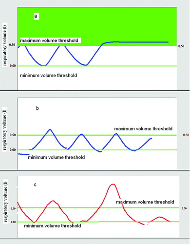
In September 2007, a protocol for training patients to an active control of their breathing cycle was introduced into our clinical practice for lung SRT, and consequently, two different groups of patients were considered for this study. Group A included 35 patients treated before the introduction of the protocol. For these patients a first CT scan was acquired in free breathing. Immediately after, they were just invited to hold their breath at maximum inhale and exhale to acquire a second and third set of images at the two extreme phases of the respiratory cycle. The second B group (36 patients) were trained to check the regularity of their respiratory pattern as displayed by the monitor of the Active Breathing Coordinator computerized spirometer (ABC, Elekta, Crawley, UK). The ABC device digitizes breathing volumes and displays continuously the patients’ breathing cycle Citation[15].Typical examples of breathing curves displayed on the ABC monitor are shown in a-c. The airflow can be temporarily closed for breath-holding at a predetermined volume, setting a threshold level. By visual feedback, patients of Group B were trained to maintain a reproducible and shallow breathing cycle Citation[15] trying to reduce physiologically their respiratory volume. Two threshold levels were set at the maximum inhale and minimum exhale breath volumes individually identified to acquire 2 corresponding CT data sets in breath hold. The breath-holding at maximum inhale is shown in a. A third scan was acquired setting the threshold level approximately at midway between the two for further information on the tumor position during the whole cycle. To ensure reproducibility of the breathing pattern between CT imaging and free breathing treatment session, patients of group B check their respiratory cycle by ABC monitor both during CBCT acquisition and treatment delivery (b).
Figure 1. Active Breathing Control for reproducibility and reduction of respiratory volumes. a) Thresholds at maximum and minimum volumes were set for breath-hold CT scan acquisition. A breath hold at maximum inhale is shown. b) The reproducibility of the breathing volumes was checked during the free breathing CBCT acquisition and treatment delivery. c) Patients were instructed to avoid deep inspiration beyond the maximum threshold level, used for planning CT acquisition.
For both groups a GTV was delineated for each CT data set using the lung window; the extent of tumor motion was evaluated as GTV displacement between the maximal inhale and exhale phases. The overall 3D tumor displacement was analyzed performing descriptive statistics separately for group A and B to assess the efficacy of the adopted protocol for the reduction of respiratory internal motion. One-tailed student's t-test was used for testing differences between the means of the two groups. Statistical significance was considered at p < 0.05. The 3 GTVs delineated on the multiphase CT data sets, were fused to generate the internal target volume (ITV) that represents the target volume explicitly accounting for respiratory tumor motion, as recommended by International Commission on Radiation Units and Measurements Report 62 Citation[16]. To evaluate the possible interobserver variability of GTV delineation and its effects on the assessment of tumor motion, in ten cases the GTVs were re-contoured by a second physician and variability analyzed. A uniform 4 mm margin was added to the ITV to generate a PTV that accounted for the residual positioning uncertainties after on-line image guided corrections.
Treatment planning
For treatment planning a single CT data set was used, respectively acquired in normal breathing for Group A and at the end of expiration for Group B: the information on the tumor breathing motion was contained in the ITV contour. The respiratory organ motion of any organ at risk was not considered. A treatment plan was created employing a dynamic conformal arc technique (ERGO + + planning system, Elekta): coplanar arcs covering a total range of minimum 180° and maximum 270° were shaped by means of a dynamic micro MLC with a 5 mm leaf width at the isocenter (Elekta, Crawley, UK). Due to the regular shape and reduced dimensions of the treated lesions, the multileaf collimator was conformed to the PTV Citation[17]. The majority of lesions (n = 86) were treated in a single fraction prescribing 23 Gy at the periphery of the target and requiring the PTV to be covered by the prescription isodose surface for 98% of the volume at least. For 13 lesions, prescription was 27 Gy as total dose delivered in 3 consecutive fractions in a maximum of 4 days. First and single fractions were always delivered on the same day of CT scans acquisitions. For homolateral healthy lung the following dose-volume constraints were used: for single fraction treatment, the percentage of volume receiving doses above 7 Gy (V7Gy) should be =15%; for fractionated courses, the volume receiving doses above 15 Gy (V15Gy) was requested to be =15%. All treatments were delivered by a 6 MV Linac (Elekta Synergy®).
On-line image guidance: Bony structures alignment and tumor positioning
In-room image guidance and treatment delivery were performed in free breathing employing a linear accelerator equipped with an on-board kV CBCT (Elekta Synergy® system). No particular instruction was given for breathing control to patients of group A. For group B, both the patient and a physician checked the breathing cycle on the ABC monitor during CBCT acquisition and treatment delivery ensuring that the respiratory volumes remained within the maximum threshold employed for inhale CT scan acquisition (b) and avoiding deep inspiration beyond this level (c). The aim of the whole procedure was to avoid variations of the breathing pattern between the CT images acquisition and the treatment session, ensuring consistency between the dimensions of the ITV contour and the actual respiratory range of tumor motion during IGRT.
Prior to each treatment a CBCT volumetric image was acquired with a standard protocol. The projection images (n = 640) were acquired during a rotation of 360° in approximately 2 min. The scan dose was estimated to be in the range 3-4 cGy Citation[18], Citation[19]. The projections were processed using the Elekta XVI software (version 3.5). A back projection algorithm with medium resolution (voxel size 1 mm3) was used to reconstruct the 3D volumetric images. Planning CT images, with ITV and PTV contours together with the contours of the organs at risk and the planned isocenter position, were imported to the Elekta XVI control workstation from the planning system. The daily acquired CBCT images were matched online with the imported planning CT scan, to obtain the couch shifts necessary to correct positioning errors. The precision and accuracy of the corrections detected by the XVI alignment software for the isocenter position, was checked on a weekly basis on a QA water phantom with PVC and air inserts respectively for bone and grey value matching Citation[19], Citation[20].
For evaluation of the set-up error an automatic registration on the bony anatomy in the planning CT and CBCT was performed, using the rigid body “bone” algorithm (chamfer matching) of the XVI software Citation[9]; the volume of interest for matching included several vertebrae whose position was assumed to be unaffected by the breathing motion. After alignment on the vertebrae the correct tumor positioning was visually evaluated: a physician checked that the planning ITV contour projected into the CBCT study enclosed the visible tumor on cone beam CT and, when it was outside, manual corrections were performed respect to the bone alignment using the XVI software (a,b). The underlying assumption for this alignment is that the CBCT image of the tumor can be considered as a surrogate of the ITV Citation[6], Citation[10], Citation[21]: the image acquisition time of about 2 min. comprises several breathing cycles and the shape of the moving tumor is blurred in the direction of respiratory motion creating an image of higher densities respect to the surrounding lung parenchyma; this image contains information about the tumor position, the range and pattern of its motion.
Figure 2. Tumor alignment performed by CBCT, the ITV (in blue) and the PTV (in red) contours appear superimposed on the CBCT image: (a) visual check of the CBCT tumor position respect to the ITV contour, (b) the ITV contour was manually shifted to enclose the tumor image on CBCT.
Finally, the isocenter shifts for online corrections of tumor positioning errors were performed prior to each treatment.
To compare positioning corrections obtained by manual tumor alignment with those based on bony anatomy, differences between the two sets of errors were calculated along the three axes (x, y, z) for each fraction obtaining a difference vector (Δxtarget-bone, Δytarget-bone, Δztarget-bone). The 3D difference for all lesions and all fractions was analyzed using descriptive statistics (mean, standard deviation, median, 90th percentile, maximum and minimum). The distributions were tested for normality visualizing the histogram plot as well as using the Kolmogorov-Smirnov test. The Spearmen's rank test was used to analyze the correlation between the tumor respiratory displacements and the tumor position errors relative to bony anatomy.
Rotational errors were detected by the first automatic bony structure alignment, and overall mean and standard deviations calculated along the three axes: X (LR), Y (SI), Z (AP). Correlation between rotational errors and the detected tumor misalignments relative to bony anatomy was analyzed using a Spearmen's rank test.
Inter-observer variability of the manual tumor alignment was tested by a second physician analyzing off-line 50 CBCT studies and comparing the two sets of detected errors.
Thirty post-correction, post-treatment CBCT were acquired in order to evaluate residual positioning errors and intra-fraction variability.
Six CBCT images from group B were exported to the treatment planning workstation. The visible tumor on CBCT was manually delineated to obtain a CBCT ITV, and compared to the planning CT ITV.
Results
Target volumes and tumor motion assessment
For the 71 patients included in this study a total of 99 ITV and PTV were created. The mean values for ITV and PTV for all patients were 13.1 cm3 and 23.9 cm3 (range: 2.5-117.8 cm3) respectively. Normalizing the internal target volume to the gross tumor volume delineated in the inhale CT scan and calculating the mean value for all lesions, we obtain 3.52 and 1.92 for patients of group A and group B respectively; the difference was statistically significant (p = 0.028, one-tailed student's t-test).
The extent of tumor motion was calculated as the magnitude of GTV displacement between the maximal inspiration and expiration phases and results are summarized in for 86 evaluable lesions. The mean tumor motion for all patients along the three axes was 2.8 mm (LR), 3.8 mm (AP), and 6.1 mm (SI). The resultant mean 3D tumor motion was 8.9 mm (range 0.7–34.5 mm). The mean value of the 3D vector for patients of group A, for whom no check of the breathing cycle was performed, was 14.7 mm, and it dropped to 4.7 mm, for patients of group B, who checked their breathing cycle by ABC. Larger breathing excursions for group A respect to group B were also observed when the mean 3D vector was calculated separately for mid-lower lobe lesions obtaining 19.6 mm (A) and 6.1 mm (B) and for upper lesions yielding 10.5 mm (A) and 3.7 mm (B). These differences between the two groups showed a high statistical significance (p < 0.001, one-tailed t-test).
Table I. Summary of respiratory 3D tumor motion for all patients and separately for group A and B. Group A = no specific check of the breathing cycle; Group B = visual check of the breathing cycle by Active Breathing Coordinator device.
The inter-observer differences of 3D tumor motion were inferior to 1 mm in eight of the ten examined cases, and the maximum difference was 1.4 mm. The two sets of ITVs obtained by the independent contouring of two physicians were also compared considering the volumes and geometric centers. Differences in the position of the centers were all within 1.4 mm, except one case for which a maximum of 3 mm was observed. A maximum of 20% difference was observed for the volumes.
On-line image guidance: bony structures alignment and tumor positioning
For all patients the pretreatment CBCT image was preliminary aligned on the vertebrae with the reference CT using the automatic bony structure image registration and, when necessary, manual corrections performed shifting the planning ITV contour to enclose the tumor on the CBCT image (a,b). Results for the three dimensional differences between bony anatomy and target matching for 109 fractions are shown in , for all patients and separately for group A and group B. The overall mean and standard deviation were 3.1±2.8 mm and the 90th percentile (chosen to describe most cases) was 6.6 mm. The 3D difference between target and bone alignment was inferior to 3 mm for 58% of the totality of fractions. The distributions of observed differences between tumor and bone matching both for Group A and B are shown in together with the related box plots. Both distributions are clearly not normal as it was confirmed using the Kolmogorov-Smirnov test (p = 0.03). The box plots underlined the absence of symmetry especially for data relative to group A, together with the presence in both cases of outliers corresponding to shifts larger than 10 mm. For patients of group A (no active training for breathing control) calculation of mean and standard deviation yielded 3.3±3.3 mm (90th percentile 8.0 mm) (see ). For patients of group B, trained to perform an active control of the breathing cycle, 3D tumor position error relative to the bony anatomy was 2.9±2.4 mm (mean±SD) and the 90th percentile was 6.0 mm. 3D differences between target and bony alignment smaller than 3 mm were observed in a larger number of fractions (68%) for group B than for group A (45%) reaching statistical significance (0.02 < p<0.05) using a χ2 square test: to this aim a 2×2 contingency table was created considering, both for group A and group B, two subgroups respectively with 3D difference inferior to and superior to 3 mm and χ2 statistics applied to compare the same subgroups in A and B.
Figure 3. Histograms of frequency distributions and related box-plots for 3D differences detected between bone and target alignment respectively for group A and B.
Table II. Summary of differences between tumor and bone matching detected by pre-treatment CBCT for all patients and separately for group A and B. Group A = no specific check of the breathing cycle; Group B = visual check of the breathing cycle by the Active Breathing Coordinator device.
Using Spearmen's rank test a significant correlation (ρ = 0.56) between the tumor respiratory excursion and tumor position errors relative to the bony anatomy was observed (p < 0.01) for patients of B group (), but no correlation was found for those belonging to the A group.
Figure 4. Correlation between 3D tumor respiratory movements and 3D differences between target localization and alignment on bony anatomy.
Mean absolute rotational errors about X, Y and Z axes were calculated from the data obtained by the automatic bony structure alignment and yielded respectively 0.87, 1.15 and 0.79 degrees; 90% of the observed rotational errors were below 2 degree and 95% were below 3 degrees. For four patients a rotation of 4 degree was observed. No significant correlation was found between the rotational errors and the tumor positioning errors detected after alignment of the bony structures.
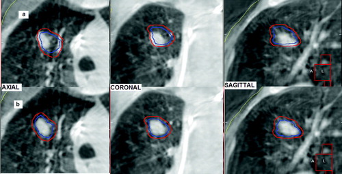
On 6 CBCT images acquired for patients of group B, a tumor contour was delineated and considered as a surrogate for the ITV. The dimensions of these CBCT ITV were compared with the respective planning ITV. For 5 lesions, the differences between the 2 volumes were all below 11%, and a maximum discrepancy of 14% was observed on the 6th patients (see ). A typical example is given in b, where the planning ITV is coherent with the CBCT tumor volume. For group A, the planned ITV was (by a visual inspection) often larger than the CBCT tumor (a), indicating a probable overestimation of the actual breathing excursion, even if this assertion needs further investigation.
Figure 5. Qualitative comparison between the ITV contour (in blue) and the dimensions of the visible tumor on CBCT (the PTV contour, in red, is also shown): a) example for a patient of group A. b) example for a patient of group B.
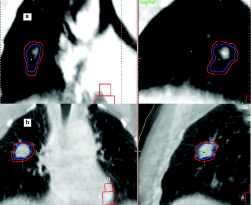
Table III. Comparison of dimensions of the ITV delineated in the planning CT scan with the volume of the tumor delineated on the CBCT image for six patients of group B.
The inter-observer variability for tumor manual alignment on 50 CBCT scans showed a mean 3D difference of 1.7±1.1 mm, with a maximum of 4.6 mm.
For residual errors and intrafractional variability of tumor positioning, 90% of the detected errors were within 3.8 mm on thirty post-correction, post-treatment CBCT. Calculation of mean 3D error and standard deviation yielded 2.3±1.1 mm.
Discussion
The outcome of free breathing lung SRT is strongly dependent on a reliable prediction of respiratory motion by ITV delineation and on an accurate target positioning. In this study we have presented our approaches, both for reduction and reproducibility of breathing motion, and for tumor positioning by kV CBCT image guidance.
The data indicated that the protocol adopted to train patients to check visually their breathing cycle by the ABC computerized spirometer was effective in reducing tumor respiratory motion. Both the mean value of the normalized ITV and the mean 3D tumor displacement calculated for patients of group B were significantly smaller than the respective values obtained for patients of group A. An analysis performed by a student's t-test confirmed the statistical significance of the observed differences between the two groups both for the ITV dimensions and the 3D respiratory motion.
The extremely large values of tumor breathing displacement found for group A need, however, some further comments: probably for planning CT acquisition, patients of group A hold their breath far from their physiological volumes both in inhale and exhale phases leading to overestimate the respiratory motion and consequently ITV dimensions (a).
Assessments of tumor motion as well as of the ITV geometric centre were scarcely affected by interobserver variability in GTV delineation, confirming the reliability of the results presented in this work.
Data obtained by CBCT IGRT for target localization indicated that, although an ITV based on multiphase CT scans was created, alignment on bony structure did not always assure a correct tumor positioning. For group A, after alignment on the vertebrae, shifts larger than 8 mm were necessary in 10% of fractions to align the planning ITV with the CBCT tumor. However, also for patients in group B in 10% of fractions tumor positioning errors relative to bony anatomy superior to 6 mm were detected. Considering that the cases included in this study were treated in one single fraction (87%), or in a maximum of three fractions (13%), our data indicated that bony structures cannot be considered a good surrogate for tumor positioning in lung SRT. Similar differences between tumor and bone alignment after the creation of an ITV have been observed by other groups Citation[6] and previously reported data, based on in room image guidance, have highlighted that large tumor positioning errors are possible when alignment on bony anatomy is used Citation[4], Citation[7], Citation[8]. Taking into account that both the ITV and PTV structures from the treatment planning and the CBCT incorporated information about the motion of the tumor, the cause of these tumor position errors relative to the bony anatomy cannot be the lack of complete 4-D information. A possible explanation for the large differences between tumor and bone alignment observed for group A, could be the lack of reproducibility of the breathing pattern between the planning CT acquisition and the CBCT acquisition. The tumor-bone positioning differences detected for patients of group B, who performed an active breathing control, may indicate that even in some of these cases the position of the moving tumor, the mean tumor position, is not stable respect to the vertebrae Citation[6], although this conclusion needs some further investigation.
However the presented data highlighted some relevant differences in target localization by CBCT between the A and B group. As already discussed, the ITV created for patients of group A probably overestimated greatly the physiological internal margin (a) in the majority of cases, but these larger ITV did not guarantee a correct tumor positioning using alignment on bony anatomy. Differences between tumor and bone matching above 8 mm are detected in 10% of fractions and the percentage of detected differences above 3 mm is significantly higher for group A than for group B. The correlation observed for group B between the 3D respiratory tumor excursion and the tumor position errors detected after bony structure matching also indicated that reducing the respiratory volumes may play a role in diminishing discrepancies between target and bone alignment. The analysis of the dimensions of the visible tumor on the CBCT image gave further relevant information on the comparison between the actual respiratory excursion and the ITV contour: for patients of group B the situation is exemplified by b, where the CBCT tumor has the same dimensions of the ITV contour on the planning CT. This was confirmed quantitatively for six patients by tumor delineation on 6 CBCT data sets ().
The present data, therefore, indicated that patient cooperation in checking their breathing cycle by ABC can offer relevant advantages: the tumor respiratory motion and the related internal margins are reduced; an ITV is created which is a reliable representation of the actual excursion of the tumor during the respiratory cycle, diminishing the risks of treating a too large or too small volume; finally, since the percentage of large tumor positioning errors respect to bony anatomy is smaller for group B than for group A, the adopted procedure appears to be helpful for diminishing the errors in the ITV absolute position respect to the bony anatomy. Even if comparing data from different groups is not easy, this could be a possible explanation also for the fact that the 3D differences between target and bone matching detected for group B (2.9±2.4 mm) are considerably lower than the values obtained by Purdie et al. Citation[8] (6.8±4.9 mm) and by Guckenberger et al. Citation[6] (5.4±1.3 mm) using CBCT IGRT. Introducing the described procedure for active breathing control required obviously some extra time (approximately 1 hour) for patients training, which was performed the day before the planning CT acquisition. The time required at the linac for setting the ABC spirometer was no more than 10 minutes to be divided among all the patients treated on the same day. In our opinion the already discussed advantages in margin reduction and reliability of the ITV obtained by this method justify the extra time requirement. Some difficulties have been encountered in patients immobilization using contemporarily the ABC device; these have partially been solved adapting the immobilization supports for the new required configuration.
The low inter-observer variability for tumor manual alignment confirmed the validity of our data.
Residual errors and intra-fractional variations for tumor positioning were small but not negligible, although slightly smaller than values previously reported Citation[10]; possible causes for these errors could be the difficulty in immobilizing the patient when the ABC device is used as well as a tumor intrafractional drift Citation[10]. Since 90% of these errors were within 3.8 mm we considered the applied isotropic 4 mm ITV-to-PTV margin safe. This margin only compensates residual and intrafractional error, since interfractional errors were corrected on-line by IGRT.
In summary, we have investigated the efficacy of image guidance by CBCT for free breathing lung SRT, in conjunction with a protocol for reduction and reproducibility of the breathing movements. The adopted protocol was effective for the reduction of tumor respiratory excursion and of the related internal margin and the obtained ITV was a reliable representation of the tumor excursion during free breathing treatment delivery. Discrepancies between alignment on bony structure and tumor alignment detected by CBCT were diminished for patients trained to control their respiratory cycle by ABC, confirming that patient cooperation is crucial when reproducibility of the breathing pattern has to be achieved. However using bony structure as a surrogate for target localization can still be a cause of some larger errors and alignment based on the tumor visualization on CBCT is essential for lung stereotactic treatments.
References
- Lax I, Blomgren H, Naslund I, Svanstrom R. Stereotactic radiotherapy of malignancies in the abdomen. Methodological aspects. Acta Oncol 1994; 33: 677–83
- Lohr F, Debus J, Frank C, Herfarth K, Pastyr O, Rhein B, et al. Non invasive patient fixation for extracranial stereotactic radiotherapy. Int J Radiat Oncol Biol Phys 1999; 45: 521–7
- Wulf J, Hadinger U, Oppitz U, Olshausen B, Flentje M. Stereotactic radiotherapy of extracranial targets: CT simulation and accuracy of treatment in the stereotactic body frame. Radiother Oncol 2000; 57: 225–36
- Wang L, Feigenberg S, Chen L, Pasklev K, Ma C, et al. Benefit of three-dimensional image-guided stereotactic localization in the hypofractionated treatment of lung cancer. Int J Radiat Oncol Biol Phys 2006; 66: 738–47
- Casamassima F, Masi L, Polli C. On-line corrections using a cone-beam CT for extracranial stereotactic treatments. ESTRO 25 Radiother Oncol 2006; 84: S226
- Guckenberger M, Meyer J, Wilbert J, Baier K, Mueller G, Wulf J, et al. Cone-beam CT based image guidance for extracranial stereotactic radiotherapy of intrapulmonary tumors. Acta Oncol 2006; 45: 897–906
- Purdie TG, Moseley DJ, Bissonette JP, Sharpe MB, Franks K, Bezjak A, et al. Respiration Correlated cone-beam computed tomography and 4DCT for evaluating target motion in Stereotactic Lung Radiation Therapy. Acta Oncol 2006; 45: 915–22
- Purdie TG, Bissonette J.P, Franks K, Bezjak A, Payne D, Sie F, et al. Cone-beam computed tomography for on-line image guidance of lung stereotactic radiotherapy: Localization, verification, and intrafraction tumor position. Int J Radiat Oncol Biol Phys 2007; 68: 243–52
- Borst GR, Sonke J-J, Betgen A, Remeijer P, van Herk M, Lebesque JV. Kilovoltage cone-beam computed tomography setup measurements for lung cancer patients; first clinical results and comparison with electronic portal-imaging device. Int J Radiat Oncol Biol Phys 2007; 68: 243–52
- Guckenberger M, Meyer J, Wilbert J, Richter A, Baier K, Mueller G, et al. Intra-fractional uncertainties in cone-beam CT based image-guided radiotherapy (IGRT) of pulmonary tumors. Radiother Oncol 2007; 83: 57–64
- Hansen AT, Petersen JB, Hoyer M. Internal movement, set-up accuracy and margins for stereotactic body radiotherapy using a stereotactic body frame. Acta Oncol 2006; 45: 948–52
- Keall P. 4-Dimensional computed tomography imaging and treatment planning. In: High-precision radiation therapy of moving targets. Tepper JE Semin Radiat Oncol 2004;14:81–90.
- Mageras GS, Yorke E. Deep inspiration breath hold and respiratory gating strategies for reducing organ motion in radiation treatment. In: High-precision radiation therapy of moving targets. Tepper JE, editor. Semin Radiat Oncol 2004; 4: 65–75
- Sonke JJ, Zijp L, Remeijer P, van Herk M. Respiratory correlated cone beam CT. Med Phys 2005; 32: 1176–86
- Gagel B, Demirel C, Kientopf A, Pinkawa M, Piroth M, Stanzel S, et al. Active breathing control (ABC): Determination and reduction of breathing-induced organ motion in the chest. Int J Radiat Oncol Biol Phys 2007; 67: 742–9
- International Commission on Radiation Units and Measurements (ICRU). Report 62: Prescribing, recording and reporting photon beam therapy (supplement to ICRU report 50). Bethesda: ICRU Publications, 1999.
- Casamassima F, Masi L, Bonucci I, Polli C, Menichelli C, Gulisano M, et al. Relevance of biologically equivalent dose values in outcome evaluation of stereotactic radiotherapy for lung nodules. Int J Radiat Oncol Biol Phys 2008; 71: 145–51
- Islam MK, Purdie TG, Norrlinger BD, Alasti H, Moseley J, Sharpe MB, et al. Patient dose from kilovoltage cone beam computed tomography imaging in radiation therapy. Med Phys 2006; 33: 1573–82
- Casamassima F, Masi L, Gargioli F, Bonucci I, Menichelli C, Polli C. Clinical use of a kV cone-beam CT for IGRT: Routinely QA and patient doses. 9th biennial ESTRO meeting on physics and radiation technology for clinical radiotherapy. Radiother Oncol 2007; 84: S237
- Masi L, Casamassima F, Polli C, Menichelli C, Bonucci I, Cavedon C. Cone beam CT image guidance for intracranial stereotactic treatments: Comparison with a frame guided set-up. Int J Radiat Oncol Biol Phys ( in press).
- Wang Z, Wu QJ, Marks LB, Larrier N, Yin FF. Cone-Beam CT localization of internal target volumes for stereotactic body radiotherapy of lung lesions. Int J Radiat Oncol Biol Phys 2007; 69: 1618–24