Abstract
Materials and methods. Two registration methods based on optical flow estimation have been programmed to run on a graphics programming unit (GPU). One of these methods by Horn & Schunck is tested on a 4DCT thorax data set with 10 phases and 41 landmarks identified per phase. The other method by Cornelius & Kanade is tested on a series of six 3D cone beam CT (CBCT) data sets and a conventional planning CT data set from a head and neck cancer patient. In each of these data sets 6 landmark points have been identified on the cervical vertebrae and the base of skull. Both CBCT to CBCT and CBCT to CT registration is performed. Results. For the 4DCT registration average landmark error was reduced by deformable registration from 3.5±2.0mm to 1.1±0.6mm. For CBCT to CBCT registration the average bone landmark error was 1.8±1.0mm after rigid registration and 1.6±0.8mm after deformable registration. For CBCT to CT registration errors were 2.2±0.6mm and 1.8±0.6mm for rigid and deformable registration respectively. Using GPU hardware the Horn & Schunck method was accelerated by a factor of 48. The 4DCT registration can be performed in 37seconds. The head and neck cancer patient registration takes 64seconds. Discussion. Compared to image slice thickness, which limits accuracy of landmark point determination, we consider the landmark point accuracy of the registration acceptable. The points identified in the CBCT images do not give a full impression of the result of doing deformable registration as opposed to rigid registration. A larger validation study is being planned in which soft tissue landmarks will facilitate tracking the deformable registration. The acceleration obtained using GPU hardware means that registration can be done online for CBCT.
Organ deformation during successive image guided radiotherapy (IGRT) sessions represents a significant challenge to optimal planning and delivery of radiation doses. To facilitate a more precise conformation of doses to the tumor thereby sparing normal tissue, multiple 3D cone beam CT (CBCT), conventional CT or MRI datasets can be acquired during the treatment course. To update existing dose plans based on this newly obtained data, the data must be correlated to a reference dataset. For this task a registration method is needed. A per pixel-based (deformable) registration technique is required to fully account for the non-homogeneous deformation throughout the volume. However, such methods are much more time consuming to perform compared to methods estimating homogeneous (rigid or affine) transforms. Moreover, if the deformable registration is not regularized sufficiently it can result in physically non-plausible deformations causing significant errors in subsequent dose calculations. In this paper we evaluate the accuracy of two fully automated image based deformable registration methods driven by the concept of optical flow Citation[1], Citation[2]. These methods were chosen based on our previous experience with registration of 2D MRI for online MR temperature monitoring Citation[3]. As a preliminary validation study we report the result of using one of these methods for registering 4DCT lung acquisitions and the other for registering head and neck CBCT and conventional CT acquisitions.
To compute such complex registrations in a clinically acceptable time frame, we implemented the two algorithms in parallel on a commodity graphics processing unit (GPU), an emerging platform for general purpose computation. The methods used in the study presented here are easily parallelizable making them ideal for GPU implementation. Furthermore, the running times of these methods are relatively short even in a non-accelerated version meaning that a significant acceleration will allow us to do deformable registration in very short time frames. Several other deformable registration methods have already been demonstrated with significant speedups on GPUs Citation[4–6]. Consequently, this paper also includes an evaluation of the running times of the two algorithms.
Materials and methods
Optical flow based registration
The process of estimating optical flow means finding a quantitative measure of how image intensity information has changed between two images. Technically both images are regarded as part of one mathematical function where spatial changes have occurred in the time between acquisitions transforming one image into the other. The optical flow is a vector field consisting of the changes in space coordinates. These vectors can be thought of as ‘optical velocity’ vectors showing the direction of image intensity flow. We focus on two optical flow based methods for deformable image registration; a 3D version of the Horn & Schunck algorithm Citation[1] and the extension of this algorithm by Cornelius & Kanade Citation[2] to handle intensity changes that do not arise as a direct consequence of geometric motion, i.e. intensity variation due to physical properties of the acquisitions themselves.
The Horn & Schunck method is based on an assumption of preserved image intensity in the two 3D images to be registered. This means that it only works for registering images of the same modality and only for images with consistent grey values when multiple image sets are compared. It is also assumed that the deformation is smooth. This is in general a valid assumption for soft tissue deformation. The Horn & Schunck method is thus suitable for registering successive CT images due to the reproducibility of Hounsfield Units for this modality.
When registering MR to MR or CBCT to CT the assumption of intensity preservation is no longer valid. In the CBCT modality the Hounsfield Units are affected by the larger contribution from x-ray scatter. Also the design of the detector and the image reconstruction algorithm used has an impact on Hounsfield unit reproducibility for CBCT. To facilitate handling of intensity differences, Cornelius & Kanade extended the original algorithm thus enabling it to tolerate some deviation from the assumption. In their work it was further assumed that the non-motion-related intensity differences are smoothly varying in space.
Both our implementations utilize a multi-resolution approach. This means that the organ deformation is first approximated on low resolution versions of the 3D acquisitions to be registered. The result of this coarse registration is then used as a starting point for a registration at a higher resolution. This continues until the deformation has been approximated at the highest resolution. This strategy enables us to systematically handle modes of deformation at different scales.
GPU based registration
The very specialized parallel hardware architecture of modern GPUs enables them to perform a vast number of numerical calculations in a short time frame allowing them to outperform the CPU in normal computers for a number of applications. The degree of GPU acceleration of an algorithm attainable depends on how suitable the algorithm is for being split into a large number of small computations that can be run simultaneously. The registration methods we focus on here are very suited for such a parallelization, and thus we have utilized the computational capabilities of a GPU for accelerating the computations required in the Horn & Schunck and Cornelius & Kanade methods. The GPU implementations are based on the CUDA framework from Nvidia Citation[7].
Image material
The Horn & Schunck registration has been evaluated on the POPI-model which is a 4D thorax virtual phantom Citation[8]. It consists of 10 CT data sets of resolution 482×360×141 which have been acquired at different breathing phases during a single breathing cycle. The images were acquired at the Léon Bérard Cancer Center, Lyon, France. In each data set corresponding to a breathing phase 41 landmark points have been manually identified, and these points are used for our validation. The voxel spacing of the acquisitions is 0.98×0.98×2.0 mm3.
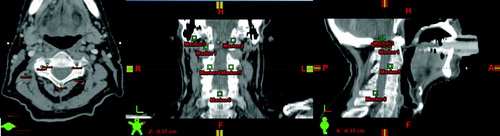
The image material used for validating the Cornelius & Kanade method is a series of 6 CBCT images of a head and neck cancer patient and a conventional planning CT image acquired at the Department of Oncology, Aarhus University Hospital. The scans have been conducted weekly during the treatment course starting at the first fraction. The CBCT images are of dimensions 512×512×51 with a voxel spacing of 0.47×0.47×3.0 mm3, while the conventional CT image is of dimensions 512×512×55 with a voxel spacing of 0.78×0.78×3.0 mm3. Validation of bone alignment is based on 6 landmark points in each 3D data set. These points have been manually positioned prior to registration at easily identifiable positions on the bony anatomy of the cervical vertebrae and the base of skull representing clinically relevant match points. Positioning of these points is illustrated in .
Figure 1. Visualization of the positioning of landmark points on the images acquired from the head and neck cancer patient.
Registration validation studies
Three series of registration experiments have been carried out:
CT to CT registration using the Horn & Schunck registration method: Following the convention from the POPI initiative all images from the 4D data set (at time phases numbered 0, 2, 3, 4, 5, 6, 7, 8 and 9) have been registered to the reference image at phase 1.
CBCT to CBCT registration using the Cornelius & Kanade registration method: The CBCT images numbered 2 to 6 have been registered to CBCT image 1.
CBCT to CT registration using the Cornelius & Kanade registration method: The CBCT images have been registered to the planning CT image.
For the Horn & Schunck method a reference CPU based implementation has also been implemented allowing us to compare the computation times between the CPU and GPU versions.
Image preprocessing
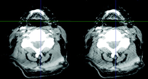
The CBCT images were processed using the GREYCstoration image denoising filter Citation[9]. As the publicly available implementation of this filter works in two dimensions, an in-house program has been used that simply filters each image slice independently. The effect of the filter is to remove noise (and in some cases artifacts from the CBCT reconstruction) while preserving the edge contrast between different kinds of morphology. See for an example.
Figure 2. The effect of applying the GREYCstoration filter to a head and neck CBCT image. The unfiltered image is the one on the right. The level of noise has been reduced without blurring the image. Window-level settings have been set to emphasize the difference between the two images.
The registration methods we present in this paper are designed to estimate the detailed deformation of morphology. If there is global displacement of patient position (that is translation and/or rotation) between two images it is necessary to do a rigid alignment of the images before the deformable registration in order to supply the method with a suitable starting point for estimation of organ deformation. The rigid registration method we use is based on the Insight Registration and Segmentation Toolkit (ITK). The measure used to compare images is based on mutual information. Input images are filtered using a threshold filter so that only bone morphology is included in the rigid registration. Again a multi-resolution approach is taken.
For validation study 1 no image preprocessing was required as the images were already rigidly aligned. In validation studies 2 and 3, a rigid registration was required. A bounding box corresponding to the physical extent of CBCT image 1 has been cut out of the planning CT image and resampled to the same resolution as the CBCT images.
Results
Validation study 1: Registration of the POPI 4DCT data set
The registration accuracy, evaluated on the target registration error (TRE) of landmark positions, is summarized in . The distances are calculated as the Euclidian length of 3D vectors. Original average landmark distance was 3.5 mm±2.0 mm. After registration, this average distance was equal to 1.1 mm±0.6 mm.
Table I. Target registration error (TRE) compared to original distances of landmark points in the POPI data set.
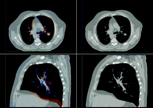
A visualization of the registration result can be seen in . In this visualization the source image is shown in a reddish color while the reference image is shown in a bluish color. Where the images align a gray scale image emerges. In the unregistered case on the left blue and red areas can clearly be seen indicating that the morphology is not aligned. In the registered case to the right these colored areas have almost disappeared indicating that the images have been successfully registered.
Figure 3. Differences between source and reference image before (left) and after (right) registration of an image from the POPI data set. A saggital slice and an axial slice are shown before and after registration. The source image is shown in a reddish color while the reference image is shown in a bluish color giving a gray scale image where the images align.
Validation study 2: CBCT to CBCT registration
In the alignment error of the landmark points positioned on the bony anatomy is summarized both before registration, after the rigid registration, and after the deformable registration. Original average landmark distance was 5.8 mm±1.1 mm. After the rigid registration, this average distance was equal to 1.8 mm±1.0 mm and after the deformable registration it was 1.6 mm±0.8 mm.
Table II. Evaluation of distances of bony landmarks for the CBCT-to-CBCT registration.
The result of registering CBCT image 3 to CBCT image 1 is visualized in . The images depicting the results of the rigid registration show an acceptable alignment of most bony anatomy, but it can be seen that the soft tissue and the area surrounding the oral cavity is not aligned. Improved alignment is obtained as a result of the deformable image registration as shown in the visualization. In a visualization of the computed transformation can be seen showing that the deformation is smooth.
Figure 4. Red/blue visualization of the difference between the rigid registration (left) and the deformable registration (right) of CBCT image 3 to CBCT image 1. A saggital slice and an axial slice are shown for each registration.
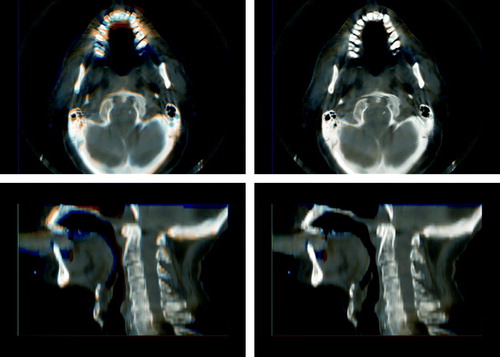
Figure 5. Illustration of the transformation applied to the axial slice shown in . The transform is used to deform a rectilinear grid with a grid spacing of 10 mm. Only the in-plane deformation can be seen.
Validation study 3: CBCT to planning CT registration
The average alignment errors after the CBCT to CT registrations are found in . After the rigid registration, this average distance was equal to 2.2 mm±0.6 mm and after the deformable registration it was 1.8 mm±0.6 mm.
Table III. Evaluation of distances of bony landmarks for the CBCT-to-CT registration.
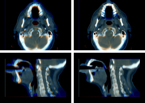
The result of registering CBCT image 6 to the planning CT image can be seen in . Again it can be seen that even though the skull and spine is aligned after the rigid registration, deformable registration is needed to account for changes in jaw positioning and deformation of soft tissue.
Figure 6. Red/blue visualization of the difference between the rigid registration (left) and the deformable registration (right) of CBCT image 6 to the planning CT image. A saggital slice and an axial slice are shown for each registration.
Time consumption
On an Intel Core 2 CPU at 2.4 GHz the Horn & Schunck registration used for the each 3D image in the POPI dataset in validation study 1 takes 30 minutes. On an Nvidia Geforce 8800GTX GPU in the same machine each registration takes 37 seconds, making the GPU version 48.7 times faster.
For the 3D Cornelius & Kanade method we did not write a CPU reference implementation. Subsequently we do not know the exact difference in processing time between CPU and GPU. However we expect the acceleration of this method to be somewhat smaller than for the Horn & Schunck method due to a less efficient use of socalled shared memory on the GPU. Each 3D registration of the CBCT images in studies 2 and 3 using the Cornelius & Kanade method takes 64 seconds.
Discussion
When specifying landmark points the limiting factor on the accuracy is the slice thickness. This is because a point may be between two slices which makes it hard to identify. In the light of this we consider the registration accuracy results in validation study 1 very acceptable as the mean landmark error is well below the slice thickness. This accuracy is comparable to results for the Demons algorithm previously reported in the POPI initiative Citation[8].
In validation study 2 and 3 we used landmark points to track the registration of clinically relevant points on the cervical vertebrae and the base of skull. For this preliminary study we did not do a dedicated evaluation of the error in landmark point identification but we estimate that the error in each landmark point position may be as high as 2.0 mm. The magnitude of this error is mainly due to the slice thickness of 3 mm. It is interesting to note that although the rigid registration was done on bone morphology the mean landmark error on bone morphology is reduced by the deformable registration. In all registrations the mean error is smaller than the slice thickness. As demonstrated in and a rigid registration is not sufficient in describing the geometrical difference between the images. However these geometrical differences have been substantially reduced by the deformable registration.
Based on these studies we are optimistic that the Cornelius & Kanade method is suitable for registering head and neck CBCT images from a series of radiotherapy treatments to the planning image. Hopefully this will allow us to compensate for the unreliable Hounsfield units by using the inverse transformation of the one found in validation study 3 to map the Hounsfield units from the planning CT to each CBCT. This will make it possible to evaluate the doses delivered in the treatment fraction corresponding to each CBCT acquisition by doing a dose calculation on the corrected CBCT image. This has previously been suggested by Yang et al. Citation[10]. When all CBCT images are registered to the same geometrical reference system, it will be possible to evaluate the actual accumulated dose from a series of fractions for comparison with the planned doses. This can be done by deforming the dose distributions from each CBCT to the geometrical reference frame constituted by the planning CT Citation[11]. Furthermore an accurate registration makes it possible to do automatic segmentation by transferring segmentations from the planning CT. Currently a larger head and neck CBCT registration study is being planned in which landmarks in bone as well as soft tissue will be used for accuracy evaluation. Also a smaller slice thickness will be used allowing us to more accurately positioning landmarks.
In the pursuit of online IGRT, the performance of the required image processing in a sufficiently short time frame constitutes a huge technical challenge. Using the GPU has led to a very significant reduction of the registration time. The explanation of this reduction in processing time must be found in the parallelized architecture of the GPU. An acceleration in the magnitude presented here is not only possible for the the Horn & Schunck method but should be attainable for other registration methods which lend themselves to being split into a large number of independent calculations. We expect the registration time of the methods presented in this paper to be reduced even more as the performance of graphics hardware increases. In the current implementation a fixed number of computations is performed for each image resolution. We plan to adjust the amount of computation to the degree of deformation actually present in the input images. This should also reduce computation time for most images. By splitting the images into blocks to be registered, is it also possible to distribute computations onto multiple GPUs. This does however introduce an overhead from the memory synchronization needed at block boundaries so whether or not this would speed up the registration significantly is unclear.
So far we have shown that using GPUs the mentioned registration methods can be accelerated to a level which is acceptable for use in an online setting in which the deformable registration is done while the patient is still on the treatment couch. This is the first step towards online dose plan adjustment.
The processing power of GPUs can be utilized not only for registration as presented here, but for many of the compute intensive imaging tasks in IGRT making it an ideal and cost-efficient tool, which can help us getting further towards online IGRT.
Acknowledgements
The work presented in this paper has been partly funded by Varian Medical Systems, Inc., Palo Alto, California.
References
- Horn BKP, Schunck BG. Determining optical flow. Artificial Intelligence 1981; 17: 185–203
- Cornelius N, Kanade T. Adapting optical-flow to measure object motion in reflectance and X-ray image sequences Proc. of the ACM SIGGRAPH/SIGART interdisciplinary workshop on Motion: Representation and perception. 1986;145–53
- de Senneville BD, Noe KØ, Ries M, Pedersen M, Moonen C, Sørensen TS. An optimised multi-baseline approach for on-line MR-temperature monitoring on commodity graphics hardware. Fifth IEEE International Symposium on Biomedical Imaging, Paris, France 2008 ( in press).
- Strzodka R, Droske M, Rumpf M. Image registration by a regularized gradient flow-a streaming implementation in dx9 graphics hardware. Computing 2004; 73: 373–89
- Noe KØ, Tanderup K, Lindegaard JC, Grau C, Sørensen TS. GPU accelerated Viscous-fluid deformable registration for radiotherapy 16th Medicine Meets Virtual Reality Conference, Long Beach, USA. Stud Health Technol Inform 2008; 132: 327–32
- Sharp GC, Kandasamy N, Singh H, Folkert M. Gpu-based streaming architectures for fast cone-beam ct image reconstruction and demons deformable registration. Phys Med Biol 2007; 52: 5771–83
- NVIDIA Corporation, NVIDIA CUDA: Compute unified device architecture-Programming guide 2007, pp. 1–83.
- Vandemeulebroucke J, Sarrut D, Clarysse P. The POPI-model, a point-validated pixel-based breathing thorax model. In XVth International Conference on the Use of Computers in Radiation Therapy (ICCR), Toronto, Canada. 2007.
- Tschumperlé D. Fast anisotropic smoothing of multi-valued images using curvature-preserving PDE's. Int J Comp Vis 2006; 68: 65–82
- Yang Y, Schreibmann E, Li T, Wang C, Xing L. Evaluation of on-board kV cone beam CT (CBCT)-based dose calculation. Phys Med Biol 2007; 52: 685–705
- O'Daniel J, Garden A, Schwartz D, Wang H, Ang K, Ahamad A, et al. Parotid gland dose in intensity-modulated radiotherapy for head and neck cancer: Is what you plan what you get?. Int J Radiat Oncol Biol Phys 2007; 69: 1290–6