Abstract
Purpose. Intensity modulated arc therapy offers great advantages with the capability of delivering a fast and highly conformal treatment. However, moving targets represent a major challenge. By monitoring a moving target it is possible to make the beam follow the motion, shaped by a Dynamic MLC (DMLC). The aim of this work was to evaluate the dose delivered to moving targets using the RapidArcTM (Varian Medical Systems, Inc.) technology with and without a DMLC tracking algorithm. Material and methods. A Varian Clinac iX was equipped with a preclinical RapidArcTM and a 3D DMLC tracking application. A motion platform was placed on the couch, with the detectors on top: a PTW seven29 and a Scandidos Delta4. One lung plan and one prostate plan were delivered. Motion was monitored using a Real-time Position Management (RPM) system. Reference measurements were performed for both plans with both detectors at state (0) “static, no tracking”. Comparing measurements were made at state (1) “motion, no tracking” and state (2) “motion, tracking”. Results. Gamma analysis showed a significant improvement from measurements of state (1) to measurements of state (2) compared to the state (0) measurements: Lung plan; from 87 to 97% pass. Prostate plan; from 81 to 88% pass. Sub-beam information gave a much reduced pattern of periodically spatial deviating dose points for state (2) than for state (1). Iso-dose curve comparisons showed a slightly better agreement between state (0) and state (2) than between state (0) and state (1). Conclusions. DMLC tracking together with RapidArcTM make a feasible combination and is capable of improving the dose distribution delivered to a moving target. It seems to be of importance to minimize noise influencing the tracking, to gain the full benefit from the application.
High precision external radiotherapy of moving targets is undergoing a major development. The classical approach to ensure full dose coverage of a moving target is to add enough margins to include the motion trajectory in the field, potentially leading to large volumes of healthy tissue being irradiated. The delivery of intensity modulated fields to moving targets has been questioned Citation[1–3], because of probable smearing as well as multileaf and target motion interplay effects. Prospective respiratory gating is commonly used for decreasing the dose to heart and lungs in breast cancer treatment Citation[4], Citation[5], but the outcome and feasibility together with intensity modulation has been debated Citation[6], Citation[7]. However, by monitoring a moving target it is possible to make the beam follow the motion in real-time, shaped by a Dynamic MultiLeaf Collimator (DMLC). This motion tracking method has been shown to increase the precision of the treatment dramatically Citation[8–10] and may therefore lead to decreased margins with less dose to normal tissue. Motion tracking has also shown promising results together with IMRT Citation[11–13].
Techniques of intensity modulated arc therapy offers great advantages with high precision treatments and single fractions delivered within short time. One example is the RapidArcTM technology (Varian Medical Systems, Inc.), which has been shown capable of creating a fast and highly conformal dose delivery Citation[13]. A treatment fraction is given in one single field with a time consumption of about 70 – 90 seconds (for a 2 Gy fraction), where intensity modulation is created by dynamical adjustment of gantry angle, DMLC and dose rate at the same time. However, one big concern regarding this treatment technique is treatment of moving targets. Gating does not seem to be a probable solution. The frequent starts and stops of the beam synchronized with respiration would imply starts and stops of the entire gantry rotation, which would be an excess mechanical load for the accelerator. Another possibility is the use of motion tracking.
During a feasibility test at the Copenhagen University Hospital, Rigshospitalet, RapidArcTM was tested together with a 3D DMLC tracking algorithm on a clinically installed linac. The aim with this study was to investigate the possibility of combining the two promising techniques and furthermore, deliver satisfying dose distributions to moving targets.
Material and methods
For the study a Varian Clinac iX, clinically installed at the Copenhagen University Hospital, Rigshospitalet was used. The accelerator was upgraded with a preclinical version of the RapidArcTM application. Dose calculations were made on a standalone beta Eclipse workstation capable of RapidArcTM plan optimization. Two dose plans were made, one for a real lung cancer and one for a real prostate cancer case. The lung cancer was a small peripheral tumour in the right lung, for which a plan was optimized with a target dose of 2 Gy and gantry angles running counter clockwise from 179° to 181°. The prostate cancer case was an early stage prostate cancer and a plan was made with target dose 3.3 Gy and gantry angles running clockwise from 200° to 160°. The dynamic processes of a RapidArcTM plan are stored in discrete steps of so called control points. At each control point there is information about specific MLC positions coupled to a specific gantry angle interval as well as to a specific amount of Monitor Units (MU) delivered. Both the lung plan and the prostate plan contained 177 control points each.
The linac's MLC controller was connected to an external computer, containing software with a tracking algorithm. The software was capable of reading spatial information from a motion monitoring system and translating rigid motions in 3 dimensions into MLC-movements. The 3 dimensions yet included in the algorithm was rigid translation in the treatment plane-parallel as well as perpendicular to the MLC leaf travel direction-and rigid translation along the beam direction. Although the algorithm current during this study only was capable of handling rigid motions, the formalism developed is extendable to include more complex types of motion, such as rotation and deformation. The motion monitoring was performed by a Real-time Position Management (RPM) system (Varian Medical Systems, Inc.), which uses visual detection of a reflexive marker box with an infra-red sensitive camera. The marker box type with 6 reflectors was used. The algorithm is described elsewhere Citation[11]; though, for better understanding of this work the basic principles are presented here.
The planned MLC positions of a RapidArcTM field are stored in an MLC sequence file, associated to the discrete control points of the field (177 for both plans during this study). The algorithm read this file and extracted the leaf positions at each control point into a field aperture, consisting of points at each leaf corner projected onto a plane seen from the Beam's Eye View (BEV) of the linac. The information about target motion from the monitoring system was analyzed by the algorithm and used to remap each point of the original aperture to a new location, forming a new aperture. For this new aperture the algorithm calculated the best fit of new MLC positions and sent to the MLC controller. For reaching “real-time” tracking the algorithm had the ability to compensate for the latency of the whole process, ∼200 ms from the motion monitoring until the MLC leaves had reached their new position. This compensation was made by estimating the near future positions of the target due to its earlier periodic motion.
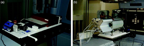
A motion platform was placed on the treatment couch, oriented so that its 1-dimensional (1D) motion was performed in the longitudinal direction along the couch. The platform was programmed to make a motion of amplitude 0.75 cm (that is, a motion of 1.5 cm side to side) with a cycle of 6 seconds. This amplitude of motion is clinically relevant, representing for example a craniocaudal motion of a lung tumour, though in the upper region of the range Citation[14]. The detectors were placed on top of the motion platform for the ability to create moving targets. For monitoring of the motion the RPM marker box was placed in an appropriate position on the moving parts of each detector system (see ).
Figure 1. The motion platform placed on the treatment couch with a) the seven29 2D-array on top, in between buildup of solid water and b) the Delta4 cylindrical phantom on top. The reflexive marker box with 6 reflectors is seen a) at the foreground corner of the moving part of the motion platform and b) on top of the Delta4.
Both the lung and the prostate plan had a collimator angle of 46°, which made the 1D motion of the platform require MLC-movements with components both parallel and perpendicular to the MLC traveling direction.
The dose detectors used were a PTW seven29 and a Scandidos Delta4 (see ). The seven29 is a flat 2-dimensional (2D) ion-chamber array with 729 cube shaped ion-chambers of 125 mm3 size and equidistant centre to centre of 1 cm. The chambers effective measurement points are situated at a depth of 5 mm beneath the phantom surface and the instrument is primarily designed for irradiation orthogonally to its surface. The seven29 had 3 cm solid water beneath and 4.5 cm solid water on top of it, which made the 2D dose plane measured lying at a total equivalent water depth of 5 cm at orthogonal irradiation (corresponding to gantry angle 0). The evaluation of the measurements was made in the PTW software (Verisoft 3.1) by visual inspections of dose profiles and iso-dose curves.
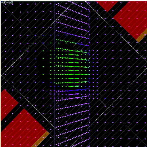
The Delta4 is a cylindrical shaped PMMA phantom, surrounding two crossing orthogonal planes with a total of 1069 p-Si diodes. The diodes are disc shaped with a volume of 0.04 mm3, with a centre to centre distance of 0.5 cm in the central area (6 cm×6 cm) and 1 cm in the outer area (up to 20 cm×20 cm) of the planes. Because of the phantom's cylindrical shape and orthogonal detector planes it is convenient for irradiation from 360° around the cylinder. An inclinometer attached to the accelerator gantry and connected to the Delta4 system was giving the instrument continuous, independent information about the gantry angle during the arc delivery. The RapidArcTM dose plans were exported from the Treatment Planning System (TPS) and imported into the Delta4 software, capable of reading the information about the MLC and gantry positions planned. For each measurement the Delta4 system was able to sort the dose information into sub-beam-structures, corresponding to the control points of the plan from the TPS. The sorting was made by associating the measured dose of each dose pulse coming from the accelerator with the actual gantry angle at this dose pulse delivery, measured by the inclinometer. The dose pulses measured during the gantry angle interval of a control point were summed together, giving the dose of that control point. In the Delta4 software the diode planes of the phantom could be shown in the planned BEV of each control point, where the diodes had different colors depending of their measured dose (see ). This made it possible to follow spatial deviations in the dose delivery from that expected due to the planned BEV, step by step, for the 177 control points of each of the two plans. The Delta4 software also included a gamma evaluation tool. Gamma evaluation is used for comparing dose distributions, taking both dose difference and spatial deviations in the dose delivery into account Citation[15], Citation[16]. The Delta4 software uses interpolated continuous dose distributions of a chosen reference set for the gamma evaluation. The gamma criteria used were 3% dose difference (relative to maximum dose) and 3 mm Distance To Agreement (DTA).
Figure 2. The planned BEV of the Delta4 phantom at one of the 177 control points of the state (1) measurement of the lung plan, shown in the Delta4 software. The dots represent the diode positions seen from the BEV (provided that the actual setup of the phantom agrees with that chosen in the software). In the software the dots have different colors depending on measured dose. By comparing the planned BEV with the dose measured by the diodes it is possible to detect spatial deviations in the dose delivery from that expected, step by step, at each control point.
Measurements of both the lung and the prostate plans were carried out at three different states and for both detectors respectively (see ). At state (0) “static, no tracking” the platform was fixed and the tracking application was deactivated. This static target treatment was used as the reference state, which the others were related to. State (1) “motion, no tracking” had the platform moving while the tracking application was still deactivated. This state, with a moving target without compensating for the motion, was expected to have a deviating dose distribution compared to state (0). At state (2) “motion, tracking” the platform was moving and the tracking was activated. State (2), with a tracked moving target, should ideally give the same dose distribution as state (0).
Table I. Presentation of the three measurement states used. Both the lung plan and the prostate plan were measured at each of the states listed.
Results
The measurements during this study were carried out without one single beam interruption, telling that the RapidArcTM technique and the tracking algorithm present make a feasible combination for this kind of linac (Varian Clinac iX).
The gamma evaluation results for state (1) (“motion, no tracking”) and state (2) (“motion, tracking”) compared to the reference state (0) (“static, no tracking”), are shown in for measurements of both plans with the Delta4 detector. For the lung plan the fraction of dose points passing the gamma test increased from 87% without tracking to 97% with tracking and for the prostate plan it increased from 81% without tracking to 88% with tracking.
Figure 3. The figure shows the fraction of measurement points passing the gamma test (3% dose difference, 3 mm DTA) for the measurement states (1) “motion, no tracking” and (2) “motion, tracking”, compared to the reference state (0) “static, no tracking”, for both the lung plan and the prostate plan, measured by the Delta4.
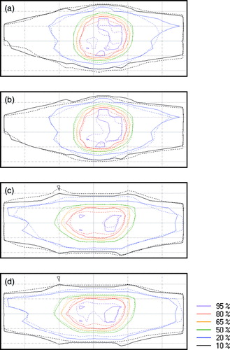
Iso-dose maps from the seven29 measurements are shown in . In the figure iso-doses of state (1) and state (2) are compared to the iso-doses of state (0) for the lung plan and the prostate plan respectively. The results from both plans follow nearly the same pattern: The iso-doses of state (1) show decreased high dose areas (80% and 95% iso-doses) and increased low dose areas (10% and 20% iso-doses) in the 1D target motion direction (up-down in the figure) compared to state (0). For the state (2) measurements the high dose areas are larger than for state (1) but they do not immediately have an increased conformity compared to state (0). The whole dose distribution at state (2) seem to have a slightly shift in the downwards direction of the image for the lung plan and in the upwards direction for the prostate plan.
Figure 4. Iso-dose curve comparisons from the seven29 measurements. Image a) and b) show measurements of the lung plan while c) and d) show measurements of the prostate plan. For all four images a)-d), the solid lines represent state (0) measurements. The dashed lines represent a) state (1) measurements of the lung plan, b) state (2) measurements of the lung plan, c) state (1) measurements of the prostate plan and d) state (2) measurements of the prostate plan. The motion of the targets was performed in the up-down direction seen in the images.
The dose measured by the Delta4 at each of the 177 control points of each plan, gave interesting sub-beam information about the dose delivery. By visual evaluation of the measurement results, control point by control point (see ), the state (0) measurements showed a very good spatial agreement with the planned BEV throughout the whole beam. By contrast, the state (1) measurements showed a dose delivery with a clear spatial deviation from the planned BEV, periodically shifting from one end to the other of the field in the direction of the platform's motion. At one end of the field, inside the planned BEV, there was an underdosage while at the opposing end of the field, outside the planned BEV, there was an overdosage. This under- respective overdosage was shifting sides with a period of 13–14 control points
for the lung plan and 8–13 control points for the prostate plan. The state (2) dose deliveries of both plans also had more spatial deviations than for state (0) but the amount of dose points deviating were much reduced and the periodic pattern was much less clear than for state (1). It was possible to distinguish periodically shifting deviations for the lung plan, with about the same period (11–15 control points) as for state (1). However, the periodical pattern was not detectable throughout the whole beam; much fewer diodes were deviating which made some periods difficult to see. There also was a tendency that the spatial shift in the dose delivery was seen only during one half of the periods while there was a good agreement with the planned BEV during the other half, that is the shift was only present in one direction. For the prostate plan it was even more difficult to distinguish a periodic pattern of spatial deviations in the dose delivery at state (2). The few periods that were possible to see had the same tendency of deviations only towards one direction, as for the lung plan.
Discussion
For measurements of a moving target without tracking (state (1)) the dose map was expected to have a decrease of the high dose volume and a smeared out low dose volume, compared to the reference static target measurements (state (0)). The iso-dose curve comparisons in show that this expectation was correct. The measurements of moving targets with tracking compensation (state (2)) were expected to give a dose distribution with an overall increased conformity to state (0) than for state (1). There are parts of the iso-dose maps of state (2) (see ) that show an improved delivery than for state (1), especially the increased high dose areas, but it is not the clear improvement that we had hoped for. However, the gamma evaluations of the Delta4 measurements gave a consistent and substantially better result for state (2) than for state (1), both regarding the lung plan and the prostate plan. Further, the sub-beam dose information per control point showed a much reduced pattern of periodically shifting spatial dose deviations for state (2) than for state (1). The conclusion of these results together is that the dose delivered to moving targets was improved with tracking compared to without tracking used.
When analyzing the results of the measurements of this study, one should keep in mind that the two detectors used are very different in construction and are intended for partly different use. One difference is the size of their individual detectors. The diodes of the Delta4 have measuring volumes of 0.04 mm3, which may be considered to measure point doses during all circumstances of this study. By contrast the ion chambers of the seven29 have effective measuring volumes of 125 mm3 and this volume may not always be considered to measure point doses. When compared, probably the mean dose measurements over the ion chamber volumes give a higher uncertainty than the point dose measurements with the Delta4, especially in the steep dose gradient regions of the dose distributions. Also the fact that the seven29 is constructed for irradiation perpendicular to the surface but was used for a 360° arc irradiation has to be considered. The intention was to compensate for the direction dependency by using a reference state, measured from exactly the same angles as the dose distributions investigated. However, the instrument was still used in a different way than for what it was designed, yielding an uncertainty of the result.
Unfortunately it was not possible to get the exact time period of the spatial dose deviations seen in the Delta4 measurements, as the Delta4 software did not give any information about the time consumption for each control point. The RapidArcTM technique, with modulation of the gantry rotation velocity during the beam, implies that the time consumption is not constant for the control points. The periods, measured to be 13–14 control points for the lung plan and 8–13 control points for the prostate plan, could therefore not be immediately correlated to the 6-seconds periods of the motion platform. However, the only difference between state (0) and state (1) was the motion of the platform, which makes it practically certain that the periodic dose deviations seen for state (1) measurements, was caused by this motion.
It was a bit surprising that the iso-dose curves from the seven29 measurements did not show an overall better result for state (2) than for state (1). Earlier laboratory studies of a simplified RapidArc technique, using the same detector type and tracking system Citation[11] have shown a substantially better agreement of both high dose and low dose iso-dose curves, for measurements of a moving target with tracking than without tracking, compared to static target measurements. One reason to this is probably that we had a noise problem in the tracking system during the study, influencing the MLC-positions during the beam. When the tracking system was activated, without any motion of the target, it was possible to see shaking multileaf-motions on the MLC-controller, looking noise related. The noise seemed to originate in the RPM system. This system is mainly developed to have a high accuracy in the AP-direction (used for respiratory gating purposes) but was here used for monitoring a motion in the SI-direction along the couch. One circumstance that may also have contributed to decreased quality of the motion information collected by the RPM system was that the monitoring camera was inappropriately positioned. The camera positioning, resulting in a skew angle to the reflector box, might perhaps explain the slight shift in the dose distributions of state (2) measurements, seen both for the iso-dose comparisons and for the periodical deviations from the planned BEV in the dose per control point evaluations.
Conclusions
The combination of the RapidArc technique and the 3D DMLC tracking algorithm present was shown to be a feasible solution. Further, the dose delivered to targets moving due to the experimental setup of this study, was improved compared to when no compensation for the motion was used. Since the completion of this feasibility study efforts have been made to further improve the tracking algorithm and also to find and reduce the noise originating from the RPM system. Further investigations are needed to fully understand all processes of this complex task and such studies are ongoing.
Acknowledgements
Thanks to Ingemar Wiberg and Görgen Nilsson (ScandiDos AB, Uppsala, Sweden) for their great support with the Delta4 detector, during the measurements as well as the analysis.
References
- Bortfeld T, Jiang SB, Rietzel E. Effects of motion on the total dose distribution. Semin Radiat Oncol 2004; 14: 41–51
- Shirato H, Seppenwoolde Y, Kitamura K, Onimura R, Shimizu S. Intrafractional tumor motion: Lung and liver. Semin Radiat Oncol 2004; 14: 10–8
- Vedam SS, Keall PJ, Docef A, Todor DA, Kini VR, Mohan R. Predicting respiratory motion for four-dimensional radiotherapy. Med Phys 2004; 31: 2274–83
- Korreman SS, Pedersen AN, Aarup LR, Nottrup TJ, Specht L, Nystrom H. Reduction of cardiac and pulmonary complication probabilities after breathing adapted radiotherapy for breast cancer. Int J Radiat Oncol Biol Phys 2006; 65: 1375–80
- Korreman SS, Pedersen AN, Josipovic M, Aarup LR, Juhler-Nottrup T, Specht L. Cardiac and pulmonary complication probabilities for breast cancer patients after routine end-inspiration gated radiotherapy. Radiother Oncol 2006; 80: 257–62
- Dietrich L, Tucking T, Nill S, Oelfke U. Compensation for respiratory motion by gated radiotherapy: An experimental study. Phys Med Biol 2005; 50: 2405–14
- Keall P, Vedam S, George R, Bartee C, Siebers J, Lerma F. The clinical implementation of respiratory-gated intensity-modulated radiotherapy. Med Dosim 2006; 31: 152–62
- Keall PJ, Cattell H, Pokhrel D, Dieterich S, Wong KH, Murphy MJ. Geometric accuracy of a real-time target tracking system with dynamic multileaf collimator tracking system. Int J Radiat Oncol Biol Phys 2006; 65: 1579–84
- Papiez L, Rangaraj D, Keall P. Real-time DMLC IMRT delivery for mobile and deforming targets. Med Phys 2005; 32: 3037–48
- Tacke M, Nill S, Oelfke U. Real-time tracking of tumor motions and deformations along the leaf travel direction with the aid of a synchronized dynamic MLC leaf sequencer. Phys Med Biol 2007; 52: N505–N512
- Sawant A. Management of three-dimensional intrafraction motion through real-time DMLC tracking. Med Phys 2008; 35: 2050–61
- McMahon R, Papiez L, Rangaraj D. Dynamic-MLC leaf control utilizing on-flight intensity calculations: A robust method for real-time IMRT delivery over moving rigid targets. Med Phys 2007; 34: 3211–23
- Otto K. Volumetric modulated arc therapy: IMRT in a single gantry arc. Med Phys 2008; 35: 310–7
- Korreman S, Mostafavi H, Le QT, Boyer A. Comparison of respiratory surrogates for gated lung radiotherapy without internal fiducials. Acta Oncol 2006; 45: 935–42
- Low DA, Harms WB, Mutic S, Purdy JA. A technique for the quantitative evaluation of dose distributions. Med Phys 1998; 25: 656–61
- Low DA, Dempsey JF. Evaluation of the gamma dose distribution comparison method. Med Phys 2003; 30: 2455–64