Abstract
Background. Volumetric modulated arc therapy (VMAT) is a radiotherapy technique in which the gantry rotates while the beam is on. Gantry speed, multileaf collimator (MLC) leaf position and dose rate vary continuously during the irradiation. For optimum results, this type of treatment should be subject to image guidance. The application of VMAT and image guidance to the treatment of a lung cancer patient is described. Material and methods. In-house software AutoBeam was developed to facilitate treatment planning for VMAT beams. The algorithm consisted of a fluence optimisation using the iterative least-squares technique, a segmentation and then a direct-aperture optimisation. A dose of 50 Gy in 25 fractions was planned, using a single arc with 35 control points at 10° intervals. The resulting plan was transferred to a commercial treatment planning system for final calculation. The plan was verified using a 0.6cm3 ionisation chamber and film in a rectangular phantom. The patient was treated supine on a customised lung board and imaged daily with cone-beam CT for the first three days then weekly thereafter. Results. The VMAT plan provided slightly improved coverage of the planning target volume (PTV) and slightly lower volume of lung irradiated to 20 Gy (V20) than a three-field conformal plan (PTV minimum dose 85.0 Gy vs. 81.8 Gy and lung V20 31.5% vs. 34.8%). The difference between the measured and planned dose was −1.1% (measured dose lower) and 97.6% of the film passed a gamma test of 3% and 3mm. The VMAT treatment required 90s for delivery of a single fraction of 2 Gy instead of 180s total treatment time for the conformal plan. Conclusion. VMAT provides a quality dose distribution with a short treatment time as shown in an example of a lung tumour. The technique should allow for more efficient delivery of high dose treatments, such as used for hypofractionated radiotherapy of small volume lung tumours, and the technique may also be used in conjunction with Active Breathing Control, where fewer breath holds will be required.
The concept of intensity-modulated arc therapy (IMAT) is not new Citation[1]. Several authors have proposed methods for arcing the gantry around the patient during radiotherapy so as to deliver dose from all directions in as short a time as possible Citation[2–9]. However, in the delivery of such techniques, the dose rate has been constant, so that multiple additive arcs have been necessary to achieve full modulation of intensity Citation[10], Citation[11].
Recently, it has become possible to deliver IMAT with continuously varying gantry speed, multileaf collimator (MLC) leaf position and dose rate, allowing the maximum possible modulation of intensity at all positions around the patient Citation[12]. This technique, known as volumetric modulated arc therapy (VMAT), promises to provide high quality dose distributions in a short treatment time. However, the demands of planning many apertures at different beam orientations, together with the requirements of verifying the correct performance of the accelerator in the delivery, make the practical implementation of the technique a challenge. This paper thus describes the process of planning, verification and delivery of VMAT by means of a case study for the first lung cancer patient treated with VMAT at our institution, in January 2008.
In order to ensure that the benefit of such an accurate, efficient technique is realised, it is appropriate to perform VMAT with image guidance. Cone-beam CT is an effective means of ensuring that the daily position of the patient is correct in three dimensions, and that the setup of the patient remains constant for the duration of the treatment. This is especially important for lung patients, where the position of the tumour may vary from fraction to fraction, in addition to any motion which may occur during the fractions themselves. Image guidance is therefore included in this study.
Material and methods
Patient history and diagnosis
A 71-year-old lady presented with a cough, haemoptysis, chest pain and shortness of breath on exertion although she remained of performance status 1. She was a non-smoker with a past medical history of a heart murmur, hypercholesterolaemia and a melanoma of the right leg treated surgically in 1984. Imaging showed a large subcarinal mass measuring 7×5 cm and a small nodule in the apical segment of the left lower lobe. Histology showed small cell carcinoma of the lung. The disease was staged as limited stage and chemoradiotherapy was prescribed. Chemotherapy consisted of six cycles of Carboplatin and Etoposide. Radiotherapy consisted of 50 Gy in 25 fractions, concomitant with cycles 5 and 6 of chemotherapy.
Treatment planning
The prescription was for 50 Gy in 25 fractions to a central normalisation point (100% isodose). The clinical objectives and constraints are shown in . The clinical target volume (CTV) was surrounded by a margin of 1 cm in the left, right, anterior and posterior directions, and 1.5 cm in the superior and inferior directions, to create the planning target volume (PTV). The area greater than 3 cm from the PTV was contoured as normal tissue. A margin of 0.5 cm was added to the spinal cord to create a planning risk volume (PRV).
Table I. Objectives and constraints used for inverse planning.
The patient was planned using AutoBeam v4.6 in-house software Citation[13]. A single coplanar clockwise arc starting at gantry angle 190° and finishing at gantry angle 170° was defined. The arc consisted of 35 control points at 10° gantry intervals. Collimator angle was fixed at 5° throughout the arc to minimize the effects of interleaf leakage and tongue-and-groove effect. The minimum allowed aperture width or length was 2.5 cm and the minimum equivalent square aperture size was 3 cm. The maximum aperture size was defined as the edge of the PTV plus a 0.5 cm margin (0.9 cm superiorly and inferiorly) to the nearest corner of the MLC leaf. The MLC movement between control points was limited to allow the gantry to rotate at close to maximum speed of 6°/s. AutoBeam performed a fluence optimisation using iterative least squares Citation[14], followed by a segmentation, and then a direct-aperture optimisation with constrained leaf positions Citation[13]. Dose grid resolution was 0.4 cm×0.4 cm×0.4 cm for the inverse planning.
After inverse planning, an automatic script was also used to transfer the plan to Pinnacle3 (Philips Radiation Oncology Systems. Madison, WI) for recalculation on a 0.25 cm×0.25 cm×0.25 cm grid. Pinnacle3 v8.0h was not designed to handle VMAT beams so the beams were created as static beams. The plan prescription was also sent directly from AutoBeam to MOSAIQ v1.41 (IMPAC Medical Systems, Inc, Sunnyvale, CA, an Elekta company) by DICOM transfer, in the absence of DICOM export for VMAT from Pinnacle3.
A backup three-field conformal plan was also created in Pinnacle3, assisted by AutoBeam's beam direction optimisation facility Citation[15], for practical purposes. The conformal plan used the same isocentre as the VMAT plan. The backup plan served as a useful benchmark against which the VMAT dose distribution could be measured. The plan consisted of three fields at gantry angles 0°, 150° and 280° and all beams were wedged to obtain the best dose homogeneity in the PTV and minimal lung V20. A 0.6 cm margin (0.9 cm superiorly an inferiorly) was allowed between the edge of the PTV and the MLC leaves, with the leaves being allowed to intrude slightly within this margin.
Pre-treatment verification
The plan was independently checked using RadCalc v4.3 (Lifeline Software, Inc., Bullard, TX). The plan was also delivered to a 22-cm high stack of Solid Water (Radiation Measurements, Inc., Middleton, WI), in the centre of which was a 0.6 cm3 ionisation chamber. An EDR2 film (Eastman Kodak, Rochester, NY) was also positioned horizontally 1 cm away from the ionisation chamber, so as to measure in a coronal plane. The delivered dose measured by the ionisation chamber was considered in relation to the dose delivered by a 10×10 cm field at 100 cm SSD (calibration conditions) so that the daily variation in output of the accelerator was excluded. The ionisation chamber measurement was repeated to evaluate repeatability of treatment. The film was scanned using a VXR-16 Dosimetry Pro film scanner (Vidar Systems Corporation, Herndon, VA) and was compared with the planned dose using Omni-Pro I'mRT (Wellhöfer-Scanditronix, Schwarzenbruck, Germany). The dose distribution was examined using a gamma plot for 3% and 3 mm.
Treatment delivery
The patient was treated with the conformal backup plan for the first two fractions as VMAT was not yet available. The patient was immobilised using an in-house designed lung board allowing the arms of the patient to be abducted. The daily procedure on a day when position was being verified, was to check the freedom of gantry rotation, acquire the verification image, check the registration of the images, and treat. The patient was treated using RTDesktop v7.0 (Elekta Ltd, Crawley, UK) and MOSAIQ v1.41.
Treatment verification
VolumeView cone-beam images (Elekta Ltd, Crawley, UK) were used for position verification. The automatic grey match function was used for image registration and corrections were made using an off-line protocol. The following correction protocol was used: on days 1-3 of treatment, cone-beam CT scans were acquired. If the error was greater than 1cm, intervention was required. The average displacement for all three days was then calculated and a correction was made for systematic errors of greater than 0.2 cm. An additional scan was acquired to confirm the correction and imaging was then done weekly.
Results
Treatment planning
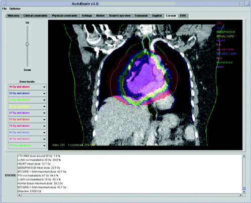
A typical aperture produced by the AutoBeam software is shown in . The greyscale map is the desired fluence as produced by the fluence optimisation. The MLC leaves of this control point, together with those of the adjacent control points, have been segmented to approximate this fluence map, and the direct-aperture optimisation has then adjusted the leaf positions so as to provide an optimal plan. The final dose distribution in AutoBeam is shown in .
Figure 1. AutoBeam inverse planning system showing a typical control point with greyscale fluence map and constrained MLC leaves after segmentation.
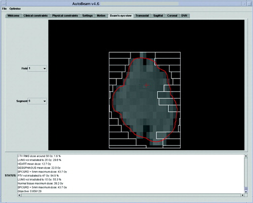
Figure 2. AutoBeam inverse planning system showing a coronal dose distribution after inverse planning.
In Pinnacle3 the dose is normalised to a point near to the isocentre, chosen to give good coverage in the range 95 to 107%. The VMAT plan is compared with the conformal backup plan in . Dose-volume histograms for this comparison are shown in , and full dose statistics are shown in . The PTV coverage is slightly better for the VMAT plan and lung V20 is slightly lower. Heart dose and spinal cord dose are slightly higher for the VMAT plan, although both doses are acceptable, with the spinal cord maximum dose within a tolerance of 46 Gy and therefore not judged to be significant. Conformity index (defined as P∩ V95/P∪ V95, where P is the volume of the PTV and V95 is the volume encompassed by the 95% isodose) is higher for the VMAT plan. The overall volume encompassed by the 10 Gy isodose (V10) is 6.8% higher for the VMAT plan. The VMAT plan requires 271.3 monitor units, while the conformal plan requires 376.6 monitor units. The main difference in the MU arises due to the absence of wedges in the VMAT plan.
Figure 3. A transaxial comparison of the VMAT dose distribution (left) and the dose distribution provided by the conformal backup plan (right).
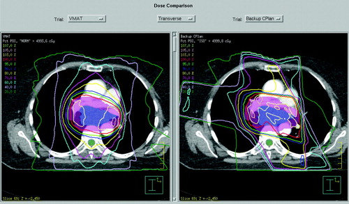
Figure 4. A comparison of DVHs between the VMAT and conformal backup plans.
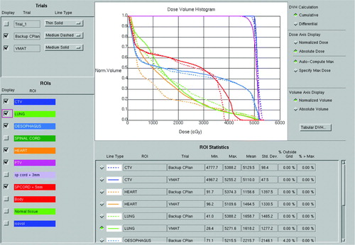
Table II. Dose statistics for the VMAT and conformal plans.
Pre-treatment verification
RadCalc records a dose of 0.8% higher than Pinnacle3. The dose measured by the ionisation chamber is 1.856 Gy, compared to 1.877 Gy with a standard deviation of 0.009 Gy over the chamber volume, calculated on the treatment planning system. No measurable difference in ionisation chamber output is observed on repetition of the delivery. Evaluating the gamma map of the coronal film, 97.6% of the high-dose region passes the gamma criterion of 3% and 3mm.
Treatment delivery
The whole process fitted within a 20 minute treatment slot. The treatment alone, without imaging, could be completed in a 10 minute treatment slot. Treatment delivery time was around 90 s, compared to 180 s for the standard conformal plan used on the first two fractions. The patient noticed the reduced time for the VMAT delivery.
Treatment verification
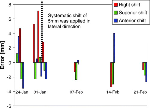
The treatment set-up errors as found by grey-scale matching are shown in . A systematic lateral shift of 0.5 cm was observed by the third scan, so an isocentre shift of 0.5 cm was made. Thereafter no shifts were necessary.
Figure 5. Summary of setup accuracy over the course of treatment.
Discussion
The case report confirms the ability of VMAT to facilitate the delivery of a high-quality treatment in a short time. For this site, where the PTV is often convex, the main advantage of VMAT is its speed of delivery compared to the conventional technique of multiple fixed fields. This is due both to the difference in MU and the extra time required between beams in the conformal plan. While such time efficient delivery is of questionable value for conventional 2 Gy fractions, it is of particular advantage in conjunction with the Active Breathing Coordinator (ABC; Elekta Ltd, Crawley, UK) to minimise the number and duration of breath holds per fraction for the large doses used in hypofractionated treatments. The reduced time of delivery with VMAT is likely to make high-dose hypofractionation with ABC a more tolerable and feasible prospect.
Other work in progress includes the investigation of VMAT for highly concave treatment volumes such as prostate and pelvic nodes or tumours of the head and neck. Use of portal images for dosimetry verification might allow VMAT to be used more widely, as the requirements for time-consuming pre-treatment verification may then be reduced. As with the evolution of commercial algorithms to date, the AutoBeam optimisation engine has further evolved in the short time since this treatment to further exploit the delivery capabilities of VMAT on the linear accelerator. The development of an efficient, in-house optimisation algorithm with its compatibility with a specific manufacturer's treatment platform and a commercial treatment planning system (for final dosimetry calculations), has been advantageous. However, such a development has required rigorous verification methods to achieve the necessary confidence in accuracy. Time consuming treatment plan comparisons which are needed to justify general implementation for given tumour sites are necessarily carried out at a late stage in this rapid development process.
VMAT data in the literature is sparse. However, some IMAT results have been published (IMAT is VMAT without the ability to change gantry speed and dose rate during the arc). Cao et al. [9] compare VMAT with previously delivered Tomotherapy (Tomotherapy, Inc., Madison, WI) plans. In all cases a clinically acceptable plan is achieved with VMAT. Duthoy et al. [11] report on seven rectal patients in whom small bowel is spared significant doses using IMAT compared with the conventional plans. However, three IMAT arcs are used to obtain the necessary dose modulation. It is expected that VMAT with its varying gantry speed and dose rate would both improve the dose modulation within one arc and speed up the delivery. It is expected that for some tumour sites, fixed field IMRT would deliver an equivalent or even superior plan in terms of quality of dose distribution, but again, with an extended treatment time. As VMAT evolves it may be able to incorporate the equivalent of fixed IMRT fields within the arc. We are currently investigating these issues further.
Acknowledgements
We would like to thank Elekta Ltd for their collaboration, particularly Dr Kevin Brown, Mr Paul Boxall and Ms Begoña Vivas. Elekta Ltd also provided financial support. We would also like to thank the team at The Royal Marsden NHS Foundation Trust for their support of and input into this project, particularly Dr Michael Thomas, Dr Ellen Donovan and Ms Sarah Helyer. AutoBeam has been developed under a grant from The Institute of Cancer Research and the present project has also received support from Cancer Research UK (program grant reference SP2312/0201). The work of Dr Juliet Brock and Professor Michael Brada is supported by The Institute of Cancer Research, The Royal Marsden NHS Foundation Trust and Cancer Research UK [CRUK grant number C46/A2131]. This work was undertaken in The Royal Marsden NHS Foundation Trust, who received a proportion of its funding from the NHS Executive; the views expressed in this publication are those of the authors and not necessarily those of the NHS Executive.
References
- Yu CX. Intensity-modulated arc therapy with dynamic multileaf collimation: An alternative to tomotherapy. Phys Med Biol 1995; 40: 1435–49
- Cameron C. Sweeping-window arc therapy: An implementation of rotational IMRT with automatic beam-weight calculation. Phys Med Biol 2005; 50: 4317–36
- Crooks SM, Wu X, Takita C, Watzich M, Xing L. Aperture modulated arc therapy. Phys Med Biol 2003; 48: 1333–44
- Earl MA, Shepard DM, Naqvi S, Li XA, Yu CX. Inverse planning for intensity-modulated arc therapy using direct aperture optimization. Phys Med Biol 2003; 48: 1075–89
- Ulrich S, Nill S, Oelfke U. Development of an optimization concept for arc-modulated cone beam therapy. Phys Med Biol 2007; 52: 4099–119
- Shepard DM, Cao D, Afghan MKN, Earl MA. An arc-sequencing algorithm for intensity modulated arc therapy. Med Phys 2007; 34: 464–70
- Luan S, Wang C, Cao D, Chen DZ, Shepard DM, Yu CX. Leaf-sequencing for intensity-modulated arc therapy using graph algorithms. Med Phys 2008; 35: 61–9
- Gladwish A, Oliver M, Craig J, Chen J, Bauman G, Fisher B, et al. Segmentation and leaf sequencing for intensity modulated arc therapy. Med Phys 2007; 34: 1779–88
- Cao D, Holmes TW, Afghan MKN, Shepard DM. Comparison of plan quality provided by intensity-modulated arc therapy and helical tomotherapy. Int J Radiat Oncol Biol Phys 2007; 69: 240–50
- Duthoy W, De Gersem W, Vergote K, Coghe M, Boterberg T, De Deene Y, et al. Whole abdominopelvic radiotherapy (WAPRT) using intensity-modulated arc therapy (IMAT): First clinical experience. Int J Radiat Oncol Biol Phys 2003; 57: 1019–32
- Duthoy W, De Gersem W, Vergote K, Boterberg T, Derie C, Smeets P, et al. Clinical implementation of intensity-modulated arc therapy (IMAT) for rectal cancer. Int J Radiat Oncol Biol Phys 2004; 60: 794–806
- Otto K. Volumetric modulated arc therapy: IMRT in a single gantry arc. Med Phys 2008; 35: 310–7
- Bedford JL, Webb S. Constrained segment shapes in direct-aperture optimization for step-and-shoot IMRT. Med Phys 2006; 33: 944–58
- Xing L, Chen GTY. Iterative methods for inverse treatment planning. Phys Med Biol 1996; 41: 2107–23
- Bedford JL, Webb S. Direct-aperture optimization applied to selection of beam orientations in intensity-modulated radiation therapy. Phys Med Biol 2007; 52: 479–98