Abstract
Background. Collimation of irregularly shaped clinical electron beams is currently based on electron inserts made of low melting point alloys. The present investigation compares a conventional electron applicator with insert and add-on eMLC-based dose distributions in the postoperative chest wall irradiation of left-sided breast cancer. Material and methods. Voxel Monte Carlo++ (VMC++) calculated dose distributions related to electron fields were compared with 10 left-sided breast cancer patients after radical mastectomy. The prescription dose was 50 Gy at a build-up maximum. The same dose was prescribed for the ipsilateral axillary, parasternal and supraclavicular lymph nodes that were treated with photons and calculated with a pencil beam algorithm. The insert beams were shaped with 1.5 cm thick Wood's metal electron inserts in an electron applicator of a Varian 2100 C/D linac. Doses for the eMLC-shaped beams were calculated for an eMLC prototype with 2 cm thick and 5 mm wide steel leaves. The same collimator-to-surface distance (CSD) of 5.8 cm was used for both collimators. Results. The mean PTV dose was slightly higher for the eMLC plans (50.7 vs 49.5 Gy, p<0.001, respectively). The maximum doses assessed by D5% for the eMLC and insert were 60.9 and 59.1 Gy (p<0.001). The difference was due to the slightly higher doses near the field edges for the eMLC. The left lung V20 volumes were 34.5% and 34.0% (p<0.001). There was only a marginal difference in heart doses. Discussion: Despite a slight increase of maximum dose in PTV the add-on electron MLC for chest wall irradiation results in practically no differences in dose distributions compared with the present insert-based collimation.
Patient specific inserts made of alloys based on Wood's metal are in widespread use for shaping of clinical electron beams in the treatment of superficial targets such as the chest wall after radical mastectomy in breast cancer. The multi-leaf collimation of electron beams has been proposed as a more advanced and potentially less laborious choice. In these studies different prototype electron few-leaf Citation[1] or multi-leaf collimators (eMLC) have been developed Citation[2–6]. Some prototypes and related calculation methods have been aimed at modulated electron beam therapy Citation[5], Citation[7–11]. However, so far the clinical application of the eMLC has been hampered by the lack of adequate treatment planning software and treatment delivery hardware that could support the use of eMLC collimated electrons. Only recently has electron beam therapy using a prototype eMLC for patients been reported Citation[11].
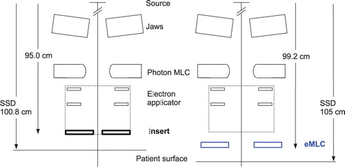
In previous eMLC prototypes the associated electron applicator of the linac was redesigned Citation[5], Citation[6] or removed for the installation of the eMLC Citation[2], Citation[4]. In the latter case both fixed source-to-surface (SSD) and isocentric electron irradiations were possible Citation[2–4]. Also the use of the photon MLC with focussed tungsten leaves has been investigated Citation[12], Citation[13] for electron beam shaping. In this case, the patient should be positioned close to the treatment head (SSD between 70 and 80 cm) to reduce the in-air scatter of electrons leading to a prohibitive widening of beam penumbras (at typical SSDs of 100–110 cm). An alternative approach to reduce the in-air scatter of electrons and maintain the clinically relevant treatment distance (with acceptable electron contamination) would be to fill the treatment head with helium gas Citation[13]. It has been shown that the distance from the eMLC to the treatment head has a marked effect on the contaminating photon dose to the patient Citation[14], Citation[15]. If the eMLC is close to the treatment head the photon contamination is low but an increased in-air scatter of electrons results in wider penumbras of the electron beams. In contrast, by placing the eMLC close to the patient sharp dose profiles were obtained at the expense of an enhanced electron contamination near the field edges Citation[9], Citation[16]. This is of special importance for abutting electron and photon fields such as in the radiation treatment of chest wall after modified radical mastectomy where the scar region is often treated with an electron beam and the ipsilateral axillary lymph nodes with a matched photon beam. In this study the source-to-collimator lower surface distance was 4.2 cm longer for the eMLC compared to insert (). Based on the different geometry differences in dose distributions between the two collimators are expected.
Figure 1. Schematic view of the lower part of the Varian 2100 C/D linac treatment head for the insert (left side) and eMLC geometries (right side). Also the applied treatment distance for both collimators is shown for reference.
Both leaf thickness and material have an effect on the amount of transmitted dose and also the energy and fluence distribution of electrons scattered from leaves. In the published eMLC prototypes 2.54 cm thick steel leaves Citation[5], 1.8 cm and 3.0 cm thick brass leaves Citation[3] and Citation[4], and 1.6 cm thick leaves made of low melting point alloy Citation[6] has been used. Leaves made of steel result in higher transmission of contaminating photons and a slightly wider fluence distribution compared to tungsten Citation[5]. Also the present eMLC with 2 cm thick steel leaves Citation[16] results in a slightly higher transmission at low electron energies compared with a 1.5 cm thick Wood's metal insert. However, this structure is expected to result in only minor differences between the dose distributions, if the maximum number of electron fields was limited to two like in this study. Focussed leaf ends with an eMLC have been reported not to offer benefit over straight leaf ends Citation[9].
Recently, a new add-on eMLC prototype Citation[16], Citation[17] and a new Monte Carlo (MC) beam model Citation[18] for multi-leaf collimated electron beams were introduced. The dosimetric accuracy of the new beam model together with VMC++ dose calculation was generally within 2%/2 mm Citation[16]. In the present investigation, the add-on eMLC of Citation[16] as modelled by the new MC beam model and VMC++ dose calculation were applied for one of the most common electron treatments, namely chest wall irradiation of breast cancer after modified radical mastectomy. The purpose was to compare calculated dose distributions and dose-volume histograms (DVH) from the eMLC with those from conventional electron beam shaping (applicator with individual custom inserts).
Material and methods
Patients
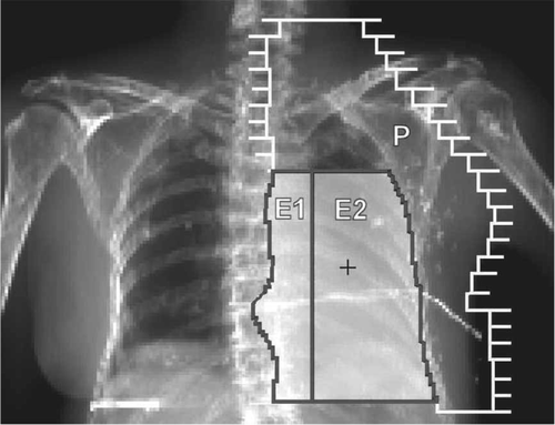
CT-scans and digitally reconstructed radiograph (DRR) images of ten consecutive left-sided female breast cancer patients after modified radical mastectomy were the basis of the study. Previously, during 2006 and 2007 the patients had been treated at the Kuopio University Hospital (KUH) according to the local practice. Therefore, the present investigation had no influence on their treatment. The ipsilateral supraclavicular, parasternal and axillary lymph nodes were treated with an anterior or anterior and posterior 6 MV beam and the chest wall (mainly representing the operated scar region) with an individually shaped electron fields at SSD 105 cm defined by an anterior DRR image of the thorax (). For the electron beam shaping conventional individually made electron inserts in standard electron applicators were used.
Figure 2. Beams eye-view of the chest wall irradiation with adjacent electron beams E1 and E2 together with a matched photon beam (P). The central axis is marked with (+) and the operation scar crossing the electron fields is shown with an X-ray positive wire.
In the present study, the electron beam shapes used in patient treatments were also realized by a new add-on electron MLC prototype. The photon beams were identical in both the conventional plans (electron applicator plus insert) and the eMLC plans. Hence, the two plans compared for each patient were (i) conventional plan with one or two insert-shaped electron fields for the chest wall and one anterior or parallel opposed anterior-posterior 6 MV photon fields for the ipsilateral lymph nodes and (ii) eMLC plan with the same fields, but the electron fields collimated with the eMLC.
For a photon field shaping the standard Varian 80-leaf MLC with the projected leaf width of 1 cm at the isocenter was applied. A fixed SSD technique with SSD 105 cm for the anterior and SSD 100 cm for the posterior photon beam was used.
Treatment planning
Planning target volume and organs at risk
The PTV consisted of the chest wall from the skin to the anterior lung surface and the ipsilateral parasternal, supraclavicular and axillary lymph nodes. The mean PTV volume was then 872 cm3 (range 596–1541 cm3). The prescribed dose to the PTV was 50 Gy. For electron beams the prescribed dose was defined at the build-up maximum in the central part of the field according to ICRU 71. Electron beam energies (6, 9 or 12 MeV) were selected such that the therapeutic range (R85) of the electron beams as closely as possible equalled or minimally exceeded the maximum thickness of the chest wall. This ensured a minimum dose of 42.5 Gy at the distal PTV surface. For photon beams the dose prescription was based on the ICRU point in the central part of the PTV. There was always a minimum dose of 45 Gy in the deepest part of the PTV in the anterior-posterior direction. For each electron and photon field the dose distribution was normalized in separate normalization points and the same normalization was used for both the insert and eMLC plans. Hence, the same dose per field was delivered at the normalization points for both plans.
Since the differences between the insert and the eMLC plans were expected to be found mainly in the high-dose regions, the PTV dose-volume parameters D5% and D10% were compared for the insert and the eMLC plans. Also the D50% volume, mean dose and standard deviation of the dose were included in the statistical analysis.
To evaluate dose to healthy tissues, the left lung and heart were defined as OARs. The V20 Gy and V30 Gy volumes were compared for the insert and eMLC plans.
Conventional electron inserts
For the electron beam shaping 1.5 cm thick individually made Wood's metal (Cerrobend®) inserts mounted in a standard 20×20 cm2 electron applicator of a Varian 2100 C/D linac were used. With a standard applicator the distance from focus to the lower surface of the insert was 95 cm i.e. the collimator-to-surface distance (CSD) was 5.8 cm at the applied treatment distance (SSD=100.8 cm). The insert aperture enclosed the PTV with a 1 cm margin. The field size was defined at the isocenter distance 100 cm, and no margin was left between adjacent fields with straight, non-diverging insert edges. The adjacent electron fields shared the same virtual source position such that the abutting field edges coincided and the isocenter was the same for both electron and photon fields.
The eMLC prototype
The electron multi-leaf collimator prototype has been described previously Citation[16]. Briefly, the eMLC consists of 5 mm wide and 2 cm thick non-motorized steel leaves mounted in an aluminium frame. The leaf ends are straight with non-focussed sides. The prototype was attached below a standard 20×20 cm2 electron applicator of the same linac that was used for insert beam calculations. The source-to-leaf lower surface distance was 99.2 cm which means that the CSD was 5.8 cm at SSD 105 cm. Hence, the same CSD was applied for both insert and eMLC plans. The planning beam shapes of the eMLC fields were identical to the insert-based field shaping, i.e. the center of the leaf ends was matched to the position of the insert field edge.
Dose calculations
Recently, we demonstrated that a more advanced field shaping with an add-on electron multi-leaf collimator (eMLC) could be accurately modelled using a Monte Carlo (MC) beam model together with Voxel Monte Carlo++ (VMC++) dose calculation. Electron beam dose calculations were done by the VMC++ dose calculation algorithm Citation[19], Citation[20] implemented in a research version of the Nucletron Oncentra MasterPlan treatment planning system (version 1.5). Photon beam dose calculations were done with a pencil beam algorithm using a standard version of the TPS. The calculations for the eMLC fields were done with an extended version of the beam model implemented in a research version of the TPS. Both the insert and eMLC dose calculations were based on beam data from the same Varian 2100 C/D linac at KUH. A detailed description of the beam model for the eMLC and achieved accuracy have been published elsewhere Citation[17], Citation[18].
The VMC++ dose calculations were performed with 5×10⁴ electrons cm−2 sampled from the plane of the insert or the eMLC. The mean statistical uncertainty in the voxels with the dose above 50% of the maximum dose was less than 1%. Electron transport and dose scoring was done in approximately 3.3 mm cubic voxels the size of which was defined automatically by the treatment planning system without user control. Treatment planning system dose calculations were performed using a Pentium 4, 2.53 GHz single processor PC with one gigabyte of RAM.
Data analysis
The statistical analysis of the treatment plans were performed using the SPSS® version 14.0. A two-tailed statistical significance between the insert and eMLC plans was calculated using the paired samples t-test or a non-parametric Wilcoxon signed ranks test. A p-value smaller than 0.05 was considered statistically significant.
Results
In the dose distribution for the eMLC the dose was slightly pronounced near the edges of the adjacent electron fields compared to the insert plan (a and b). illustrates that despite of the small differences between the plans, the higher doses for the PTV with the eMLC resulted in a slightly improved DVH.
Figure 3. Electron beam dose distributions for one of the patients with 6 and 9 MeV electrons and 6 MV photons, (a) insert plan and (b) eMLC plan. The PTV is marked with a white line.
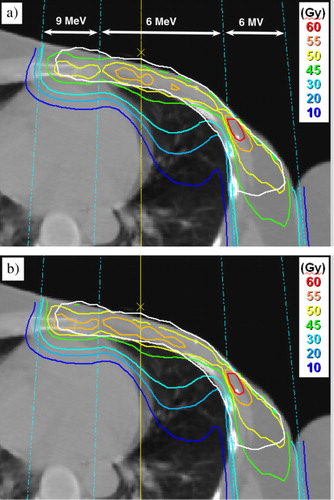
Figure 4. Dose-volume histograms for the insert (--) and eMLC (-) plans for the patient of .
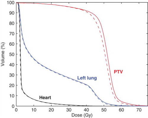
The mean PTV and OAR doses were slightly higher for the eMLC generated plans as shown in . The largest differences accounting for approximately 4% of the prescribed dose were found in the mean dose and in the high dose region of the PTV (D5%, D10%). Similarly, there were statistically significant differences in the DVH parameters for lung V20 Gy and V30 Gy and with the heart which had the smallest differences between the insert and eMLC plans. For both the left lung and heart the differences were small (0.5% or less).
Table I. Dose and volume differences of the DVH calculations between the eMLC and insert-based treatment plans (N=10)
The mean calculation time per electron beam for the insert plans was 10.7 minutes compared to 14.8 minutes for the eMLC plans with 1% statistical uncertainty of the dose. At a 2% uncertainty level the mean calculation times decreased by a factor of more than two.
Discussion
Electron beam patient dose calculations for an add-on multi-leaf collimator prototype were compared with the conventional electron inserts in chest wall irradiation of left-sided breast cancer. The calculations were performed using dedicated beam models for both the eMLC and the insert. For the eMLC beams a new beam model Citation[18] was used that enables accurate clinical Monte Carlo calculations for an add-on electron MLC. The accuracy of the new beam model is within 2%/2 mm when using low electron beam energies and extended SSD Citation[16]. Similar accuracy of the dose calculations for the insert beams have been reported Citation[21–25], which enables an accurate analysis of the differences between insert and eMLC plans.
It has previously been described that with the respective add-on type eMLC the dose near the field edges is slightly pronounced compared with a conventional applicator due to the shorter CSD Citation[6], Citation[9], Citation[16] at SSD 100 cm. However, when applying the same CSD 5.8 cm this results in only marginal differences in PTV and OAR doses compared to a conventional electron applicator with insert (). For the eMLC plans the dose was slightly higher compared to the insert plans (a and b). This may be due to (i) different shape of the eMLC field (saw-toothed edges), (ii) different source-to-collimator distance or (iii) different thickness and material of the collimators.
The beam edges of the insert field and saw-toothed edges of the eMLC fields are slightly different. However, this is expected to result in only minor differences between the dose distributions close to the skin surface. Furthermore, the lateral scatter of electrons reduces further the effect at larger depths. Since the intensity distribution with low energy eMLC beams are smooth already at the surface Citation[5], the saw-toothed field shape is not seen in isodoses at the dose maximum depth Citation[9].
Using the same CSD 5.8 cm for both collimators leaves just enough space for patient positioning. However, a longer CSD (e.g. 10 cm) would likely have made the differences in penumbra and dose inside the field edge even smaller. Hence, the already slight differences in dose distributions should be even smaller at larger CSD.
In conclusion, the presented add-on eMLC results in practically no differences in dose distributions compared with the present insert-based collimation. Therefore, a replacement of inserts with eMLC is potentially feasible. A remotely controlled eMLC device with adequate software would facilitate these kinds of treatments. However, issues related to the clinical implementation of the eMLC such as mounting of the eMLC, collision avoidance and quality assurance need to be further studied.
Acknowledgements
One of the authors (Tero Vatanen) was financially supported by grants from Kuopio University Hospital (EVO-grant) and Nucletron Scandinavia AB.
References
- Al-Yahya K, Hristov D, Verhaegen F, Seuntjens J. Monte Carlo based modulated electron beam treatment planning using a few-leaf electron collimator-feasibility study. Phys Med Biol 2005; 50: 847–57
- Gauer T, Albers D, Cremers F, Harmansa R, Pellegrini R, Schmidt R. Design of a computer-controlled multileaf collimator for advanced electron radiotherapy. Phys Med Biol 2006; 51: 5987–6003
- Gauer T, Sokoll J, Cremers F, Harmansa R, Luzzara M, Schmidt R. Characterization of an add-on multileaf collimator for electron beam therapy. Phys Med Biol 2008; 53: 1071–85
- Hogström K, Boyd R, Antolak J, Svatos M, Faddegon B, Rosenman J. Dosimetry of a prototype retractable eMLC for fixed-beam electron therapy. Med Phys 2004; 31: 443–62
- Ma C-M, Pawlicki T, Lee M, Jiang SB, Li JS, Deng J, et al. Energy- and intensity-modulated electron beams for radiotherapy. Phys Med Biol 2000; 45: 2293–311
- Ravindran B, Singh I, Brindha S, Sathyan S. Manual multi-leaf collimator for electron beam shaping-a feasibility study. Phys Med Biol 2002; 47: 4389–96
- Al-Yahya K, Schwartz M, Shenouda G, Verhaegen F, Freeman C, Seuntjens J. Energy modulated electron therapy using a few leaf electron collimator in combination with IMRT and 3D-CRT: Monte Carlo-based planning and dosimetric evaluation. Med Phys 2005; 32: 2976–86
- Deng J, Lee M, Ma C-M. A Monte Carlo investigation of fluence profiles collimated by an electron specific MLC during beam delivery for modulated electron radiation therapy. Med Phys 2002; 29: 2472–83
- Lee M, Jiang S, Ma C-M. Monte Carlo and experimental investigations of multileaf collimated electron beams for modulated electron radiation therapy. Med Phys 2000; 27: 2708–18
- Ma C-M, Ding M, Li J, Lee M, Pawlicki T, Deng J. A comparative dosimetric study on tangential photon beams, intensity-modulated radiation therapy (IMRT) and modulated electron radiotherapy (MERT) for breast cancer treatment. Phys Med Biol 2003; 48: 909–24
- Ma C, Li J, Jin L, ElDib A, Fan J, Price RA, et al. Advanced mixed beam treatment techniques for breast and head and neck cancers. Int J Radiat Oncol Biol Phys 2007; 69: S47
- Du Plessis FCP, Leal A, Stathakis S, Xiong W, Ma C-M. Characterization of megavoltage electron beams delivered through a photon multi-leaf collimator (pMLC). Phys Med Biol 2006; 51: 2113–29
- Karlsson M, Karlsson M, Ma C. Treatment head design for multileaf collimated high-energy electrons. Med Phys 1999; 26: 2161–7
- Olofsson L, Karlsson M, Karlsson M. Effects on electron beam penumbra using the photon MLC to reduce bremsstrahlung leakage for an add-on electron MLC. Phys Med Biol 2005; 50: 1191–203
- Olofsson L, Karlsson M, Karlsson M. Photon and electron collimator effects on electron output and abutting segments in energy modulated electron therapy. Med Phys 2005; 32: 3178–84
- Vatanen T, Traneus E, Lahtinen T. Dosimetric verification of a Monte Carlo electron beam model for an add-on eMLC. Phys Med Biol 2008; 53: 391–404
- Vatanen T, Traneus E, Lahtinen T. A new add-on electron multi-leaf collimator (eMLC): Dosimetry and dose calculation using a new beam model with Voxel Monte Carlo. Radiother Oncol 2006; 81: S166
- Traneus E, Vatanen T, Lahtinen T. Beam model for multi-leaf collimated high-energy electron beams. Radiother Oncol 2006; 81: S28
- Kawrakow I. VMC++. Electron and photon Monte Carlo calculations optimized for radiation treatment planning, advanced Monte Carlo for radiation physics, particle transport simulation and applications. Proc. of the Monte Carlo 2000 Conf. Lisbon (Berlin: Springer 2001).
- Kawrakow I, Fippel M, Friedrich K. 3D electron dose calculation using a Voxel based Monte Carlo algorithm (VMC). Med Phys 1996; 23: 445–57
- Cygler J, Daskalov G, Chan G, Ding G. Evaluation of the first commercial Monte Carlo dose calculation engine for electron beam treatment planning. Med Phys 2004; 31: 142–53
- Cygler J, Lochrin C, Daskalov G, Howard M, Zohr R, Esche B, et al. Clinical use of a commercial Monte Carlo treatment planning system for electron beams. Phys Med Biol 2005; 50: 1029–34
- Mika S, Christ G. Experimentelle Validierung eines Monte-Carlo-basierten Bestrahlungsplanungssystems für Elektronenstrahlung. Strahlenther Onkol 2007; 183: 150–6
- Scherf C, Scherer J, Bogner L. Verifikation und Anwendungen des voxelbasierten Monte-Carlo-(VMC++-) Elektronen-Dosismoduls von Oncentra™ MasterPlan. Strahlenther Onkol 2007; 183: 81–8
- Traneus E, Ahnesjö A, Fippel M, Kawrakow I, Nusslin F, Zeng G, et al. Application and verification of a coupled multi-source electron beam model for Monte Carlo based treatment planning. Radiother Oncol 2001; 61: S102