
Abstract
Background: Accurate patient positioning is crucial in stereotactic body radiation therapy (SBRT) due to a high dose regimen. Cone-beam computed tomography (CBCT) is often used for patient positioning based on radio-opaque markers. We compared six CBCT-based set-up strategies with or without rotational correction.
Material and methods: Twenty-nine patients with three implanted markers received 3-6 fraction liver SBRT. The markers were delineated on the mid-ventilation phase of a 4D-planning-CT. One pretreatment CBCT was acquired per fraction. Set-up strategy 1 used only translational correction based on manual marker match between the CBCT and planning CT. Set-up strategy 2 used automatic 6 degrees-of-freedom registration of the vertebrae closest to the target. The 3D marker trajectories were also extracted from the projections and the mean position of each marker was calculated and used for set-up strategies 3–6. Translational correction only was used for strategy 3. Translational and rotational corrections were used for strategies 4–6 with the rotation being either vertebrae based (strategy 4), or marker based and constrained to ±3° (strategy 5) or unconstrained (strategy 6). The resulting set-up error was calculated as the 3D root-mean-square set-up error of the three markers. The set-up error of the spinal cord was calculated for all strategies.
Results: The bony anatomy set-up (2) had the largest set-up error (5.8 mm). The marker-based set-up with unconstrained rotations (6) had the smallest set-up error (0.8 mm) but the largest spinal cord set-up error (12.1 mm). The marker-based set-up with translational correction only (3) or with bony anatomy rotational correction (4) had equivalent set-up error (1.3 mm) but rotational correction reduced the spinal cord set-up error from 4.1 mm to 3.5 mm.
Conclusions: Marker-based set-up was substantially better than bony-anatomy set-up. Rotational correction may improve the set-up, but further investigations are required to determine the optimal correction strategy.
Introduction
Stereotactic body radiation therapy (SBRT) is characterized by escalated doses and sharp dose gradients delivered in one to six fractions [Citation1,Citation2]. Unlike conventionally fractionated treatments, the averaging effect of random set-up errors on dose delivery is limited. Accurate patient set-up at each fraction is therefore crucial to ensure tumor coverage and healthy tissue sparing [Citation3].
Stereotactic body frames and in-room cone-beam computed tomography (CBCT) can be used for precise patient set-up [Citation4]. However, internal motion of the tumor with respect to the bony anatomy cannot be excluded [Citation3–5]. Hansen et al. [Citation4] and Guckenberger et al. [Citation1] found that the overall targeting uncertainty was dominated by internal motion in liver and lungs requiring margins up to 10 mm in the superior–inferior (SI) direction even with a perfect patient set-up on bony anatomy. In lung SBRT, it is often possible to directly register the tumor in the reconstructed CBCT volume with the planning CT. However, in the liver, tumors are not visible in CBCT images and set-up relies on surrogates such as the diaphragm dome, bony anatomy or implanted fiducial makers.
Implanted fiducial markers have become the clinical standard as they are better surrogates for the target position than the diaphragm dome or bony anatomy provided that they are implanted close to the tumor [Citation5]. However, they often appear blurred and cause image artefacts in CT or CBCT images [Citation6]. Wunderink et al. compared marker guided set-up using the end-exhale markers positions and rotational degrees of freedom with conventional set-up methods such as frame-based set-up and registration on bony anatomy or the diaphragm dome [Citation3]. They found day-to-day marker constellation rotations up to 7.2° in the exhale phase and poor correlation between marker and bony anatomy displacements. In a study based on contrast-enhanced breath-hold CTs with visible liver tumors, Seppenwoolde et al. compared marker-constellation translation and rotation set-up with marker-constellation translation only set-up and nearest marker translation set-up [Citation5]. They reported similar accuracy for the three strategies. Worm et al. used the time-resolved 3D marker trajectories from the CBCT projections for set-up on the mean marker positions of implanted fiducial markers [Citation6]. These trajectory-based mean marker positions are determined objectively with sub-millimeter accuracy [Citation7]. They are more representative of the actual time-averaged position during free breathing than marker positions obtained from conventional pretreatment CT or CBCT volumetric reconstructions as they provide the actual time-resolved 3D marker motion during CBCT acquisition (6).
Six degrees-of-freedom (DoF) couches are becoming widespread in the clinics for rotational set-up corrections [Citation8]. However, no clear recommendation can be found on how to use 6DoF set-up for liver patients. In this retrospective study, we compare a range of set-up strategies with or without rotational correction based on the reconstructed CBCT volume or the marker trajectories obtained from the CBCT projections. The geometric set-up error of the different set-up strategies is quantified and compared.
Material and methods
This study included 29 patients treated with three or six fractions SBRT for primary cancer or metastases in the liver. All patients had three cylindrical gold markers implanted percutaneously near the tumor under ultra-sound guidance (Goldlock gold seeds, 1 × 3 mm, Beampoint, Kista, Sweden). The patients were included in a previous intrafractional motion study [Citation9]. All patients were immobilized in a stereotactic body frame (SBF, Elekta, Crawley, UK) and 23 of the patients were treated with abdominal compression to reduce breathing motion. The patients were treated in three fractions (26 patients) or six fractions (three patients) on Trilogy linear accelerators with On-Board Imager Systems (Varian Medical Systems, Palo Alto, CA). There were therefore in total 96 fractions, each with a pretreatment CBCT consisting of approximately 670 two-dimensional projections (11 Hz, 125 kV, 80 mA, 13 ms) obtained during a 360° gantry rotation of approximately 60 seconds.
Planning and set-up strategies
Six set-up strategies were compared. All translations were calculated along the right–left (RL), SI and anterio-posterior (AP) axes. The rotations were calculated around each axis: pitch around RL, roll around SI and yaw around AP. The origin of the coordinate system was the treatment isocenter. All set-up strategies are summarized in the upper part of .
Table 1. Correction method, magnitude of rotational corrections, and set-up error for six investigated set-up strategies.
The mid-ventilation phase of a 3-mm slice thickness 4DCT scan was used for treatment planning. The centroid position of each gold marker was manually delineated in the mid-ventilation phase with a typical uncertainty of 1–2 mm as previously calculated by Beddar et al. [Citation10].
Set-up strategy 1 was a manual marker match, which is the clinical standard in our institution. At treatment, a medical physicist manually registered each individual marker from the CBCT to the planning CT and the couch was translated according to the mean of the individual marker registrations. Automatic registration was not feasible due to blurring and streaking artefact in the reconstructed CBCT volume [Citation6].
For one patient (three fractions), the online match was performed on only 2 markers. For 12 fractions from 6 patients, the online match was a compromise of bony anatomy match and marker match. Thus, the match was not performed online on the three markers at a total of 15 fractions. For these fractions, the manual marker match for this study was performed offline rather than online by the medical physicist.
Set-up strategy 2 was a bony anatomy set-up. It was calculated in Offline Review (Varian Medical Systems) with an automatic 6 degree-of-freedom (DoF) rigid registration of the reconstructed CBCT to the mid-ventilation phase of the planning 4DCT on 3–4 vertebrae at the SI position of the markers.
To assess the robustness or reproducibility of the automatic registration, the CBCT of the first treatment fraction of each patient was registered repeatedly four times, and the standard deviation of the resulting rotation was calculated. For the first fraction, the registration closest to the mean of the four repeated registrations was used as the bony anatomy set-up position. For the remaining fractions, the registration was only performed once. All automatic registrations were inspected visually.
Set-up strategies 3–6 all used marker trajectories obtained from the CBCT projections. The three markers were automatically segmented in each CBCT projection and the 3D trajectories of each markers were estimated as described in the literature [Citation7,Citation9,Citation11]. In short, an in-house template-based method able to handle multiple and overlapping markers was used for marker segmentation in the CBCT projections (11). The segmentation was visually verified. The 3D marker trajectories were estimated from the segmented 2D motion by a probability-based method (7) and used to calculate the mean position of each marker during the CBCT.
Set-up strategy 3 was a trajectory-based set-up with only translation correction, which is similar to Worm et al. [Citation6]. The translation was calculated as the difference between the centroid of the mean marker positions during the CBCT and the centroid of the planned marker positions.
In set-up strategy 4, the marker constellation from the CBCT was rotated using the rotations from the bony match and the translations were then calculated as the difference between the centroid of the rotated constellation and the centroid of the planned marker positions.
Set-up strategies 5 and 6 included rotational correction of the marker constellation. The translations and rotations of the constellation were calculated using singular value decomposition (SVD) [Citation9,Citation12–14]. The rotations were constrained to ±3° in set-up strategy 5 and unconstrained in set-up strategy 6.
To assess the robustness of the SVD calculated marker constellation rotations against uncertainties in the mean marker positions, each individual marker was shifted by ±0.5mm along each axis (RL, SI, AP), and the translations and rotations were recalculated with each marker shift. The standard deviation of the rotations for the 19 possibilities was reported.
Set-up errors
For each set-up strategy and CBCT scan, the set-up marker error was calculated as the root-mean-square (rms) difference between the trajectory-based mean marker positions during the CBCT scan after the applied set-up correction and the planned marker positions. The strategies were compared using a two-sided paired t-test with a 5% confidence level.
Internal interfraction marker constellation motion
The internal interfraction translations and rotations of the marker constellation with respect to the bony anatomy were calculated using SVD between the mean marker positions in each CBCT and the planned marker positions after bony anatomy match between the CBCT and the planning CT. For each patient, the range of the interfraction translations and rotations was calculated as a measure for the day-to-day variation.
Spinal cord position
The set-up error of the spinal cord was calculated for all set-up strategies except the bony anatomy set-up, where this error was zero by definition. The spinal cord set-up error was calculated as the difference between the spinal cord position in the CBCT after the set-up correction and the spinal cord position in the planning CT. Here, the spinal cord position was defined as the center of the spinal cord at the SI position of the markers. Since spinal cord set-up errors in the CC direction typically have much less dosimetric impact than errors in the axial plane, both the full 3D set-up error and the 2D set-up error in the RL-AP plane were reported.
Impact of rotational correction on the isocenter position
Ideally, the isocenter is placed in the tumor and the markers are placed closely around the tumor. However, in reality there was often a distance between the centroid of the marker constellation and the isocenter. A rotation of the marker constellation therefore resulted in a translation of the isocenter that increased with marker-isocenter distance. To quantify this effect, the isocenter translation for all trajectory-based set-up strategies with rotation correction (strategies 4, 5, 6) was calculated for each CBCT and compared with translational only set-up (strategy 3). The geometry is shown in the Supplementary Figure 2(a)). The Pearson’s correlation coefficient was calculated between the isocenter shift and the marker-isocenter distance.
Results
Robustness of rotation estimations
The standard deviations for repeated bony anatomy rotations did not exceed 0.5° (Supplementary Table 1). The standard deviations for the marker constellation rotations with 0.5mm marker shifts were particularly large in the yaw angle for two patients (Supplementary Table 1). The markers were arranged in an almost co-linear geometry which resulted in large rotation changes when a marker was shifted by 0.5mm. These two patients were excluded for the remaining part of the study. The Supplementary Figure 1 shows the marker geometry for the two excluded patients and for a patient with low rotational uncertainty. The mean trajectory-based rotations for the 27 included patients were below 0.8° (Supplementary Table 1).
Set-up errors
The bony rotation was below 1° in all directions (). The rotations based on marker translations were larger with mean rotations close to 3° in all directions (). Rotations were constrained in 56 CBCTs (62%) from 22 patients for strategy 5. The largest root-mean square set-up errors were observed for the bony anatomy set-up, and the smallest errors occurred for the trajectory-based set-up with unconstrained rotations (, ). There was no significant difference between strategy 3 (trajectory-based set-up with only translational corrections) and strategy 4 (trajectory-based translations with bony match rotations) (p = 0.97). All the other set-up errors were significantly different from each other (p ≪ 0.01).
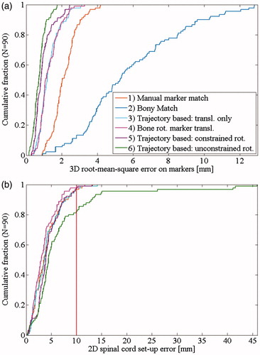
Figure 1. Cumulative distributions of the 3D root-mean-square error on the markers for all the set-up strategies (a) and the 2D error (RL-AP) on the spinal cord for strategies 1 and 3–6 (b). The vertical line indicates 10 mm which is commonly used as planning risk volume (PRV) margin.
Internal interfraction marker constellation motion
The mean and range of internal rotations were of the order of 3° in all directions and the largest translations occurred in the SI direction (). Fifteen patients had either large range () or mean () internal interfraction marker constellation motion (exceeding 1.5 cm or 5°). The largest internal rotations occurred around the AP axis (yaw) with a maximum of 24.3°.
Figure 2. Internal target motion per fraction for: (a) Eight patients with large motion range (>1.5 cm/5°). (b) Seven patients with large mean internal motion (>1.5 cm/5°). Patient treated without abdominal compression are shown with a full symbol.
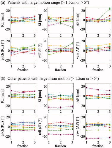
Table 2. Absolute internal interfraction motion of the marker constellation relative to bony anatomy for 90 CBCTs and range of internal motion for 27 patients when compared to the planning CT.
Spinal cord position
The distance between the marker constellation centroid and the spinal cord had a median (and range) of 13.0 cm (8.2–18.3 cm).The set-up error of the spinal cord was smallest for set-up strategy 4 (marker-based translation and bony rotation) and largest for set-up strategy 6 (trajectory-based with unconstrained rotation) where four clear outliers with 2D spinal cord set-up errors above 25 mm were observed ( and ). Three of these were from a same patient who had roll and yaw rotations larger than 15° and a relatively large 3D distance of 16.8cm between the marker constellation centroid and the spinal cord.
Table 3. Spinal cord set-up error for the marker-based set-up strategies.
The fourth outlier (spinal cord 2D set-up error of 26.1 mm) was the patient with the largest internal motion range. This patient was treated with abdominal compression. The compression plate position was well reproduced compared with planning for the first 2 fractions, but not for the third fraction where large internal translations and rotations were observed ().
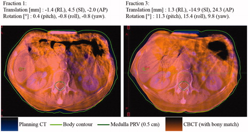
Figure 3. Patient with large marker constellation rotation relative to bony anatomy at fraction 3, possibly due to a poorly reproduced abdominal compression position. The CBCT is registered to the planning CT based on bony anatomy. The markers are not visible on this image because they are implanted cranially to the abdominal compression. The specified translations and rotations are the internal marker constellation motion with respect to the bony anatomy as compared to the planning CT.
Impact of rotational corrections on the isocenter position
The median (and range) of the distance between the marker constellation centroid and the tumor was 4.7 cm (0.6–10.6 cm). The mean 3D isocenter shifts caused by rotational corrections were 1.1 mm for the bony rotations, 2.2 mm for the constrained marker constellation rotations and 4.0 mm for the unconstrained marker constellation rotations (Supplementary Table 2). The isocenter shift was significantly (p ≪ 0.001) correlated with the isocenter-marker centroid distance with Pearson’s correlation coefficients of 0.65 for the bony rotation, 0.63 for the constrained marker constellation rotations and 0.42 for the unconstrained marker constellation rotations (Supplementary Figure 2(b)).
Discussion
We have compared six set-up strategies for liver SBRT combining translational and rotational corrections on bony anatomy or markers. The reference marker positions were the delineated positions from the planning CT. The mean marker positions after set-up correction relative to the planned reference positions were calculated using the markers trajectories obtained from CBCT projections.
The set-up error was largest for the bony anatomy set-up (strategy 2). This illustrates internal interfraction motion and has been reported previously [Citation1,Citation4]. The manual marker match (strategy 1), which is our current clinical standard, was substantially more accurate with mainly two causes of errors: first, it is a difficult and subjective process to match the blurred markers from the reconstructed CBCT to the planning CT. Second, this strategy did not correct for marker constellation rotations. The problem of blurred markers is solved by the trajectory based set-up methods (strategies 3–6), which provide accurate determination of both the mean marker positions during the CBCT and the needed translations and rotations for optimal alignment of the marker constellation with the planning CT. The trajectory estimated mean marker position has been shown to be accurate within 0.3 mm [Citation6]. With an assumed uncertainty of 0.5 mm on the mean marker positions, the mean and maximum uncertainty of the estimated marker constellation rotation were 0.7° and 1.8°, respectively (Supplementary Table 1). Worm et al found a mean 3D error of 1.6 mm matching individual markers for 15 liver SBRT fractions [Citation6]. We found a slightly larger 3D rms error of 2.2 mm with strategy 3 due to marker constellation rotation and deformation. Our study was performed on 90 fractions and also investigated the effect of rotational corrections in trajectory-based set-up and conventional CBCT-based set-up.
Trajectory based set-up with no rotational correction (strategy 3) and with rotational correction based on bony anatomy (strategy 4) resulted in similar marker alignment accuracy, but the latter had significantly smaller set-up errors of the spinal cord. It indicates that the beam alignment relative to the overall patient anatomy was closer to the treatment plan. The marker alignment accuracy was improved by applying rotational corrections calculated from the marker constellation, both when the rotations were unconstrained (strategy 6) and constrained to ±3° (strategy 5), which is a typical restriction for 6D couch adjustments. In the case of the unconstrained rotations (strategy 6), there was still a mean residual 3D error of 0.8 mm due to deformations of the marker constellation. The applied rigid translations and rotations did not correct for scaling (enlargement or shrinking of the constellation) or angular deformation of the marker constellation. Considerations on marker constellation rotations versus deformations were reported previously in an intra-fraction motion study (See Supplementary material of Ref. [9]).
The apparent marker constellation rotation cannot be distinguished from local liver deformations, marker migration or uncertainty in marker delineation () and may not reflect the actual rotation especially if the markers are not placed close to and surrounding the target [Citation3,Citation15]. Therefore, the ideal use of rotational set-up correction remains unclear. Rotational correction based on bony vertebrae match (strategy 4) seems to be a feasible conservative set-up strategy that gives the best alignment of the spinal cord (), the same marker set-up accuracy as translational only set-up (strategy 3) (, ), and very similar isocenter alignments within the liver as translational only set-up (Supplementary Figure 2). Contrary, the unconstrained trajectory-based rotational correction (strategy 6) gives unrealistic and infeasibly large rotation corrections with large spinal cord set-up errors exceeding 45 mm in the axial plane (), and a treatment area in the liver that can deviate up to 30mm compared with no rotational correction (Supplementary Figure 2(c)). Constraining the rotational corrections to ±3° (strategy 5) may be a suitable compromise for clinical use, but compared with vertebrae rotational corrections this correction leads to higher spinal cord set-up errors () and larger shifts of the treated area in the liver (Supplementary Figure 2). It is unknown whether these shifts are beneficial for the alignment of the tumor. More investigations including deformable image registration and assessment of the relative positions of the markers and the tumor are needed in order to fully evaluate a 6D set-up correction strategy.
A limitation of our study is that the tumor itself was not visible and its real position was therefore unknown, whereas Seppenwoolde et al. [Citation5] visualized the tumor in contrast enhanced CTs to assess the quality of the markers as surrogate for the actual tumor position. They reported the results of a set-up strategy based on marker translations and rotations and compared it to translation only and nearest marker set-up correction strategy. They reported similar accuracy for the three strategies and concluded that rotational correction did not necessarily improve the accuracy. For the current study, the results are in favor of vertebra based rotational corrections.
We observed up to 16.9° (roll) and 24.6° (yaw) day-to-day rotations of the marker constellation with respect to the bony anatomy. An actual internal rotation of this magnitude is very unlikely. However, for one patient the rotations were very stable over all three fractions indicating either systematic internal liver rotations, systematic local liver deformations, marker migration or inaccurate reference marker positions due to artefacts in the planning 4DCT. Wunderink et al. [Citation3] found day-to-day marker constellation rotations of up to 7.2° in the exhale phase and low correlation between the bony anatomy and marker displacements. A difference between the studies is that we used marker trajectory based rotation calculations whereas Wunderink et al. used end-exhale positions in CT scans. However, the end-exhale [Citation3] or breath-hold [Citation5] position of the tumor and the markers may not be representative of their positions during treatment due to substantial breathing induced variations [Citation9,Citation16–19]. Park et al. [Citation19] observed considerable differences in motion characteristics between simulation and treatment. It may therefore be preferable to use the complete trajectory of the markers over several breathing cycles to characterize the markers positions on the day of treatment.
In conclusion, we have compared six CBCT-based set-up strategies using either reconstructed volume or projection images, with and without rotational correction based on bones or implanted fiducial markers. Marker-based set-up was substantially better than bony-anatomy set-up. Trajectory-based set-up improved the accuracy compared with manual marker match. Rotational correction may improve the set-up, but further investigations including tumor localization relative to fiducial markers are required to determine the optimal correction strategy. To our knowledge, this was the first large comparative study on the accuracy of trajectory-based set-up corrections relative to conventional CBCT based set-up.
IONC_1288925_supplemental_material.zip
Download Zip (413.9 KB)Acknowledgement
This work was supported by the Danish Cancer Society and Varian Medical Systems, Palo Alto, CA.
Disclosure statement
The authors report no conflicts of interest. The authors alone are responsible for the content and writing of this article.
Additional information
Funding
Related Research Data
References
- Guckenberger M, Sweeney RA, Wilbert J, et al. Image-guided radiotherapy for liver cancer using respiratory-correlated computed tomography and cone-beam computed tomography. Int J Radiat Oncol Biol Phys. 2008;71:297–304.
- Høyer M, Muren LP. Stereotactic body radiation therapy-a discipline with Nordic origin and profile. Acta Oncol. 2012;51:564–567.
- Wunderink W, Méndez Romero A, Seppenwoolde Y, et al. Potentials and limitations of guiding liver stereotactic body radiation therapy set-up on liver-implanted fiducial markers. Int J Radiat Oncol Biol Phys. 2010;77:1573–1583.
- Hansen AT, Petersen JB, Høyer M. Internal movement, set-up accuracy and margins for stereotactic body radiotherapy using a stereotactic body frame. Acta Oncol. 2006;45:948–952.
- Seppenwoolde Y, Wunderink W, Wunderink-van Veen SR, et al. Treatment precision of image-guided liver SBRT using implanted fiducial markers depends on marker-tumour distance. Phys Med Biol. 2011;56:5445–5468.
- Worm ES, Høyer M, Fledelius W, et al. On-line use of three-dimensional marker trajectory estimation from cone-beam computed tomography projections for precise setup in radiotherapy for targets with respiratory motion. Int J Radiat Oncol Biol Phys. 2012;83:e145–e151.
- Poulsen PR, Cho B, Keall PJ. A method to estimate mean position, motion magnitude, motion correlation, and trajectory of a tumor from cone-beam CT projections for image-guided radiotherapy. Int J Radiat Oncol Biol Phys. 2008;72:1587–1596.
- Gevaert T, Verellen D, Engels B, et al. Clinical evaluation of a robotic 6-degree of freedom treatment couch for frameless radiosurgery. Int J Radiat Oncol Biol Phys. 2012;83:467–474.
- Bertholet J, Worm ES, Fledelius W, et al. Time-resolved intrafraction target translations and rotations during stereotactic liver radiation therapy: implications for marker-based Localization accuracy. Radiat Oncol Biol. 2016;95:802–809.
- Beddar A. S, Kainz K, Briere TM, et al. Correlation between internal fiducial tumor motion and external marker motion for liver tumors imaged with 4D-CT. Int J Radiat Oncol Biol Phys. 2007;67:630–638.
- Fledelius W, Worm E, Elstrøm UV, et al. Robust automatic segmentation of multiple implanted cylindrical gold fiducial markers in cone-beam CT projections. Med Phys. 2011;38:6351–6361.
- Umeyama S. Least-squares estimation of transformation parameters between two point patterns. IEEE Trans Pattern Anal Machine Intell. 1991;13:376–380.
- Tehrani JN, O’brien RT, Poulsen PR, et al. Real-time estimation of prostate tumor rotation and translation with a kV imaging system based on an iterative closest point algorithm. Phys Med Biol. 2013;58:8517–8533.
- Eggert DW, Lorusso A, Fisher RB. Estimating 3-D rigid body transformations: a comparison of four major algorithms. Mach Vis Appl. 1997;9:272–290.
- Worm ES, Bertholet J, Høyer M, et al. Fiducial marker guided stereotactic liver radiotherapy: Is a time delay between marker implantation and planning CT needed? Radiother Oncol. 2016;99:1–4.
- Worm ES, Høyer M, Fledelius W, et al. Three-dimensional, time-resolved, intrafraction motion monitoring throughout stereotactic liver radiation therapy on a conventional linear accelerator. Int J Radiat Oncol Biol Phys. 2013;86:190–197.
- Case RB, Sonke J-J, Moseley DJ, et al. Inter- and intrafraction variability in liver position in non-breath-hold stereotactic body radiotherapy. Int J Radiat Oncol Biol Phys. 2009;75:302–308.
- von Siebenthal M, Sze´kely G, Lomax AJ, et al. Systematic errors in respiratory gating due to intrafraction deformations of the liver. Med Phys. 2007;34:3620
- Park JC, Park SH, Kim JH, Yoon SM, Song SY, Liu Z, Song B, Kauweloa K, Webster MJ, Sandhu A, Mell LK, Jiang SB, Mundt AJ, Song WY. Liver motion during cone beam computed tomography guided stereotactic body radiation therapy. Med. Phys. 2012;39:6431.