
 ?Mathematical formulae have been encoded as MathML and are displayed in this HTML version using MathJax in order to improve their display. Uncheck the box to turn MathJax off. This feature requires Javascript. Click on a formula to zoom.
Abstract
Introduction: As proton therapy becomes increasingly well established, there is a need for high-quality clinically relevant in vivo data to gain better insight into the radiobiological effects of proton irradiation on both healthy and tumor tissue. This requires the development of easily applicable setups that allow for efficient, fractionated, image-guided proton irradiation of small animals, the most widely used pre-clinical model.
Material and methods: Here, a method is proposed to perform dual-energy proton radiography for inline positioning verification and treatment planning. Dual-energy proton radiography exploits the differential enhancement of object features in two successively measured two-dimensional (2D) dose distributions at two different proton energies. The two raw images show structures that are dominated by energy absorption (absorption mode) or scattering (scattering mode) of protons in the object, respectively. Data post-processing allowed for the separation of both signal contributions in the respective images. The images were evaluated regarding recognizable object details and feasibility of rigid registration to acquired planar X-ray scans.
Results: Robust, automated rigid registration of proton radiography and planar X-ray images in scattering mode could be reliably achieved with the animal bedding unit used as registration landmark. Distinguishable external and internal features of the imaged mouse included the outer body contour, the skull with substructures, the lung, abdominal structures and the hind legs. Image analysis based on the combined information of both imaging modes allowed image enhancement and calculation of 2D water-equivalent path length (WEPL) maps of the object along the beam direction.
Discussion: Fractionated irradiation of exposed target volumes (e.g., subcutaneous tumor model or brain) can be realized with the suggested method being used for daily positioning and range determination. Robust registration of X-ray and proton radiography images allows for the irradiation of tumor entities that require conventional computed tomography (CT)-based planning, such as orthotopic lung or brain tumors, similar to conventional patient treatment.
Introduction
In recent years, technical developments and increasing numbers of proton treatment facilities worldwide established this therapy for the treatment of specific, solid tumor entities. However, the amount of available data regarding the effects of proton irradiation on tissue in vivo remains rather small [Citation1]. Preclinical in vivo models have been studied in several publications, yet small animal irradiation is often conducted in non-targeting (i.e., whole body irradiation) setups [Citation2], for purposes not relevant for clinical treatment [Citation3] or with targeted irradiation setups that rely on the reproducibility of the animal’s positioning through external fixation, e.g., earpins [Citation4] or plastic boluses [Citation5–7]. Accordingly, methods suitable for image-guided proton irradiation of normal tissue and subcutaneous as well as orthotopic tumor models in small animals need to be established to make preclinical in vivo research of proton irradiation in clinically relevant settings more feasible. Positioning of small animals, especially for irradiation of subcutaneous tumor models is often realized with room lasers. However, orthotopic tumor models as well as immunosuppressed animals which need to be kept under specific pathogen free conditions, e.g., transport boxes or bedding units, require image-guided positioning of the target volume at the experimental site.
In this manuscript, a method is suggested for proton radiography-based treatment planning and positioning verification of small animals at an experimental proton beamline using clinically relevant beam energies. The approach exploits the fact that the passage of a proton beam through matter influences both the beam’s fluence distribution and residual energy distribution. The latter effect can be enhanced by the use of different proton energies for the imaging. Highly sophisticated proton radiography methods such as proton microscopy [Citation8] or particle tracking [Citation9,Citation10] yield image resolutions that can compete with conventional X-ray imaging but are technically demanding. The presented imaging method, on the other hand, respects the need for practicability and mobility as well as low image acquisition dose that results from fractionated animal irradiation at proton beamlines without a permanently installed, dedicated imaging setup. Importantly, the suggested imaging method applies the same beam that is used for the treatment itself, thus providing an inherently fixed spatial reference of the acquired image to the beam’s isocenter. Also, water-equivalent path length (WEPL) values of the imaged objects are provided, which can help reducing uncertainties in beam energy selection to correctly position the proton Bragg peaks inside the target volume.
Material and methods
In this chapter, the key principles of the approach towards small animal proton radiography are outlined, followed by the description of the experimental realization and data processing. The designed setup was optimized regarding robustness and efficiency.
Conceptual approach
The underlying idea is to acquire radiographic images of a mouse, from here on called object, with an extended uniform proton field by determining the change of proton fluence and proton energy caused by the object. Both kinds of changes (proton fluence and energy) affect the dose distribution that is measured behind the object, which is proportional to the acquired image intensity. In order to separate the sets of information, two 2D dose maps are acquired (i.e., two images) that exploit different regions of the proton Bragg curve by inserting slabs of plastic between object and detector for the image acquisition. Hence, while the object is irradiated two times with a proton field of the same energy, effectively, two different proton energies are used for the image acquisition.
The image intensity I is related to the measured 2D dose distribution of the proton field. For a perfectly uniform incident beam with proton fluence ϕ0 and energy E0, and thereby stopping power , the measured signal is proportional to
(1)
(1)
Inserting an object into the proton field leads to a change of the measured image intensity
(2)
(2)
which depends on the (spatial) fluence distribution and the energy deposition of the incident beam. Two major effects of the penetrated object are influencing the measured signal: (i) energy deposition in the object slows down the protons which causes a change in stopping power represented by the term
and (ii) inhomogeneous fluence is caused by multiple Coulomb scattering of the protons during the passage through the object denoted by Δϕobj. Additionally, a realistic incident proton field has an inherent energy and fluence inhomogeneity, represented by the terms
and
. However, only the terms
and
contain the object information and need to be extracted from the measured intensity I.
For image acquisition at high proton energies (without plastic material between object and detector), energy deposition in the object can be assumed to be negligible (). The dose measurement is performed in the plateau region before the Bragg peak of the proton depth-dose curve. Hence, the intensity variation in the signal is dominated by fluence inhomogeneity caused by proton scattering within the object. In this case, the object information is encoded in Δϕobj. This imaging mode shall be referred to as scattering mode from here on forward.
However, if material [e.g., plastic (polycarbonate) slabs] is inserted between the object and the detector, the dose acquisition is carried out in the part of the proton depth-dose curve with a steep dose gradient. Then, even small changes in the water-equivalent path length of the object are translated into measurable dose changes in the detector. Consequently, the acquired signal is an overlay of inhomogeneous fluence caused by scattering combined with energy absorption of the protons upon their passage through the material (object + slabs of plastic). This imaging mode shall be referred to as absorption mode from here on forward.
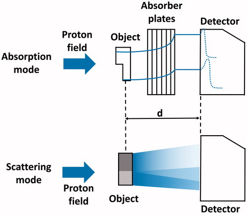
The setup of the dual-energy proton radiography concept is schematically shown in . A laterally uniform incident proton field passes through the object to be imaged. A 2D flat panel scintillation detector, placed at a distance d from the object, measures the 2D inhomogeneous dose distribution for two different imaging modes (i.e., two images): either without (scattering mode) or with (absorption mode) slabs of plastic inserted in between object and detector with no additional changes to the setup.
Figure 1. Schematic figure of the used setup for dual-energy proton radiography imaging in both imaging modes. The blue arrow on the left indicates the incident proton field. In absorption mode, the measured dose distribution encodes the residual energy of the beam after passing the object and hence the combined thickness of the plates and the object. In scattering mode, the fluence of the field is disturbed by the passage of the beam through regions of different density (here depicted as different shades of grey). The distance d between object and detector remains unchanged.
Experimental setup
A recently developed mobile double-scattering setup [Citation11] was used to produce an extended proton field with the size of 10 × 10 cm2. The scattering setup was optimized for a fixed initial proton energy of 150 MeV and provided a homogeneous field with an effective energy of E = 125 MeV. The 2D dose distributions were acquired with a ‘Lynx’ flat panel scintillation detector (IBA dosimetry, Schwarzenbruck, Germany) which has a pixel pitch of 0.5 × 0.5 mm2. The scintillation screen’s signal is measured by a CCD sensor (charge-coupled device, light-sensitive electronic detector element). Additional dosimetric measurements were conducted with an advanced Markus ionization chamber (PTW, Freiburg, Germany) to evaluate the applied doses during the imaging process. For each image, the monitor units (MU) measured by a monitor ionization chamber at the proton beam exit were recorded as a relative measure of the total dose. The dose is given as equivalent dose under the assumption of a relative biological effectiveness of 1.1.
Planar X-ray scans of objects were acquired with a small animal imaging platform [Citation12] to evaluate the feasibility of automated, rigid registration of proton radiography images and planar X-ray scans as well as to facilitate proton radiography image interpretation. The X-ray image was used to identify the lung, the skull, abdominal organs and the backbone of the object. Segmentation of structures was performed by two experienced observers (R. Bütof and A. Dietrich) and the segmented contours were then projected onto the proton radiography image for illustration and verification. This enabled the evaluation of the method’s potential for usage as a stand-alone tool or in combination with other imaging modalities such as planar X-ray.
The test objects (deceased laboratory mice) were placed within an in-house developed, opaque and fully physically closed bedding unit. This setup is designed to prevent contact of immunosuppressed mice with an uncontrolled environment allowing for future research with living animals (e.g., low hygiene and non-pathogen-free environment, respectively).
Image acquisition
Proton radiography images of the object were acquired in scattering mode and absorption mode. Additionally, images of the proton field without the object were acquired in both modes, representing the background signal of the beam. The images are referred to as Aobj and ABeam (absorption mode images) and Sobj and SBeam (scattering mode images), respectively.
Each of the eight inserted plastic slabs had a WEPL thickness of WEPLpolycarbonate = 8.85 mm. Additionally, a calibration curve for the conversion of measured image intensity to WEPL was obtained in absorption mode. Slabs of plastic with known WEPL were used as objects to relate their thickness to the measured intensity to achieve energy absorption to thickness conversion. The total number of eight absorber slabs was found to be a good compromise for the imaging of the intended mouse irradiation setup. In general, the summed thickness of absorber slabs and object to be imaged have to ensure a positioning of the detector screen in the part of the proton depth-dose curve with monotonously increasing dose, i.e., proximal to the Bragg peak. This allows for a monotonous conversion from pixel value to WEPL. On the other hand, a high resolution of the WEPL of the object can be obtained when the detector is placed close to the Bragg peak, where the dose gradient is high. Then, small changes in object thickness translate into large dose differences.
Data processing
The intensity of each image was divided by the number of applied MUs to achieve normalization. The insertion of an object into the proton field imposes a change on the measured signal, which originates from energy deposition in the object and fluence inhomogeneity (see above). These contributions can be separated mathematically to a large extent: in scattering mode, the background-corrected image S is obtained by subtracting SBeam from Sobj. According to EquationEquation (2)(2)
(2) , S is mainly dominated by the variation of Δϕobj under the assumption that energy absorption is negligible in this setup (
). The absorption mode image A has to be cleared of the fluence inhomogeneity contribution which is achieved by the following operation:
(3)
(3)
According to EquationEquation (2)(2)
(2) , A is mainly dominated by the energy loss
and therefore the radiologic thickness of the object. The measured WEPL calibration curve could be applied to the absorption image A to obtain a 2D map encoding the WEPL of the object along the beam direction.
The generated images were further processed by using 2D histograms of the pixel values from data of the images A and S. This visualization allowed for the identification of characteristic regions in the histogram that could be assigned to specific image features, e.g., the bedding unit, the outer contour or internal structures of the object. Finally, an unsharp masking algorithm was applied to the images to enhance image contrast for better visibility. All processing steps were implemented as Python 2.7 scripts.
Results
The presented imaging method for preclinical proton irradiation experiments was evaluated regarding its feasibility as a stand-alone tool (dual-energy) or in combination with a planar X-ray scan, thus requiring image co-registration. An example of a raw, unprocessed scattering mode image of a deceased laboratory mouse is shown in to depict the following processing steps more comprehensively. Faint contours of the object can be seen within the bedding unit, framed by the collimated, rectangular proton field.
Figure 2. Raw scattering mode proton radiography image of a mouse (a) within the bedding unit (b). The edge of the brass collimator which shapes the extended proton field (c) can be visually identified by the bright corona (d) at its edges.
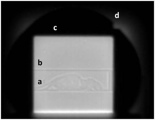
Image registration
The implemented rigid image registration method yielded highly robust and reproducible results. An example of a co-registered planar X-ray scan and the respective scattering mode proton radiography image, taken with a dose of 189.8 mGy, are shown in . Both images were automatically cropped with the bedding unit’s edges being used as landmark. Automated detection of these edges was robust and reproducible with doses as low as 6.1 mGy.
Figure 3. (A) Proton radiography image acquired in scattering mode. (B) Planar X-ray scan of the same mouse prior to proton radiography acquisition. Both images were cropped with the bedding unit used as landmark. The markers indicate the contours of internal and external structures of the mouse that could be identified in the planar X-ray image. Structures that could be distinguished were (a) abdominal intestines, (b) the stomach, (c) the lung, (d) the vertebral spine and (e) the body contour of the mouse. These contours are also shown in the proton radiography image (A) for illustration.
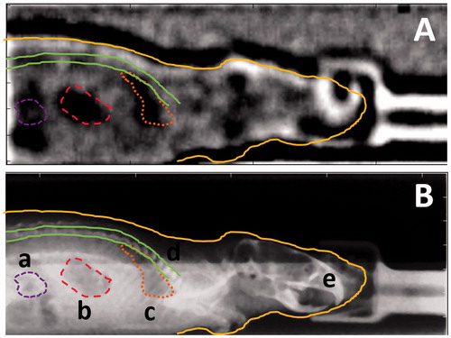
Furthermore, the outline of the object can be clearly distinguished from the background. The skull of the object with substructures can be identified whereas the front of the skull is superimposed by the signal of the fixation mask. Abdominal and intrathoracic structures are visible in the scattering mode proton radiography image, such as the stomach and the lung.
The image quality and dose dependence of the performed image co-registration was assessed by the reproducibility of the width of the bedding unit (number of pixels) in the planar X-ray image and in the proton radiography image, respectively. Varying the proton imaging dose (between 274 mGy and 6.5 mGy), lead to a stable pixel spacing ratio k with k = 5.6 ± 0.2 (n = 11, number of co-registered pairs of images), whereas imaging doses of less than 22 mGy prevented visual identification of the mouse’s body contour.
Dual-energy approach
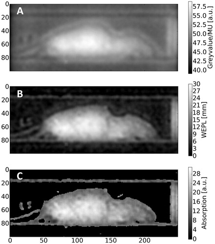
As described above, the method can also be used as a stand-alone tool to circumvent prior X-ray imaging. shows the raw data of an absorption mode proton radiography image of the object with (B) showing the result after image correction and conversion from pixel value/MU to WEPL. The applied correction removed the contribution to the signal originating from proton fluence inhomogeneity (bright corona around mouse in raw image) to a large extend. The measured maximal radiologic thickness of the object in the bedding unit, WEPLmouse+bedding ≈ 30 mm, corresponds well with the actual thickness of the object under the assumption that the tissue composition of the object in the abdominal region is equivalent to water. Furthermore, the WEPL measurement accuracy can be estimated by the WEPL values of the image background outside the bedding unit. In the case of the absorption mode image () the WEPL of the background was WEPLBackground = 0.0 ± 1.0 mm. The WEPL measurement of a plastic plate (WEPLplate = 15.0 mm) yielded a value of 15.6 ± 1.0 mm. Furthermore, geometric proportions of objects in the image (e.g., radius of the bedding unit, R = 16.5 mm) could be measured on the absorption mode image. The latter’s radius was determined through a fit and was found to be Rmeas = 17.6 mm with an R2-value of 0.95 (Supplementary Figure S6, Supplementary Materials).
Figure 4. Absorption mode proton radiography. (A) Raw image and (B) background-corrected image with conversion from pixel value/MU to WEPL applied. (C) Post-processed image using an unsharp masking filter for the enhancement of internal structures.
Subsequently, the corrected absorption-based proton radiography image allowed evaluation of the scatter-based image data in the context of the radiologic thickness as demonstrated in by means of a 2D histogram of both images (B). Within the 2D histogram (), distinct areas can be attributed to certain regions of interest in the image. Pixels containing the background of the image (mostly air) were found to be clustered in a 2D histogram region of low scattering and low-energy absorption, i.e., small WEPL. This region is marked accordingly with (a) in the 2D histogram. The rims of the bed are characterized by a strong scattering signal due to its distinct edges (air-material gradient) and an absorption signal slightly above background (b). Finally, the body of the mouse, which features a range of WEPL values greater than ∼5 mm and broadly ranging scattering signal due to internal structures, is identified as region (c) in the 2D histogram.
Figure 5. Overview of applied data processing and post-processing operations. (A) Background-corrected scattering mode image S. (B) Native 2D histogram of pixel values from background-corrected images in scattering and absorption mode along the x and y axis, respectively. The highlighted regions could be assigned to specific image features such as (c) the body of the mouse, (b) the bedding unit and (a) the air-filled image background. (C) Processed scattering mode image and (D) corresponding modified 2D histogram after the applied operations (for details see Material and methods).
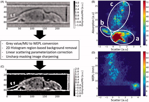
In region (c), the WEPL values correlated positively with the scatter signal, as can be seen from the 2D histogram. This characteristic originates from the energy absorption in scattering mode which is small but highly correlated with the WEPL of the object. It could be corrected in first-order by minimizing its correlation with WEPL. Subsequent application of image sharpening (unsharp masking algorithm) and suitable windowing resulted in the 2D histogram in .
The performed operations were found to produce scattering mode images which preserve the outer features (e.g., bedding unit, body contour and skull) as well as enhance contrast and detectability of internal structures such as abdominal internal structures, the lung or substructures of the skull.
Discussion
Experiments with deceased mice were conducted to evaluate the feasibility of proton radiography both in combination with other imaging modalities, e.g., planar X-ray scans or as a stand-alone tool for positioning verification and treatment planning for proton irradiation of small animals.
A high level of image detail could be obtained from the performed scattering mode imaging experiments in combination with planar X-ray imaging. Robust detection of landmarks, e.g., the bedding unit, could be achieved, allowing the method to be used as positioning tool in combination with additional external X-ray/CT imaging. Rigid registration could even be reproducibly achieved for a high noise level (doses as low as 22 mGy). The co-registration of scattering mode images and X-ray images can be reliably performed using the bedding unit as a rigid reference frame. The positioning accuracy in this setup is inherently limited by the uncertainty of the co-registration (given by the pixel spacing ratio k, Δk = ± 0.2), the spatial resolution of the used X-ray device (± 0.2 mm) [Citation12] and the Lynx detector’s pixel pitch (±0.5 mm). The squared sum of these uncertainties give an estimate of the theoretically achievable positioning accuracy with the proposed setup. The suggested estimate yields a positioning uncertainty of ±0.6 mm.
The presented approach is also promising as a stand-alone method for image-guided irradiation of small animals. The hind leg and the tail of the mouse can clearly be identified in the scattering mode image which allows sparing of healthy surrounding tissue (e.g., abdomen) by conformal proton irradiation and adequate positioning of the animal. This is of key importance to prevent undesired harmful normal tissue reactions, especially if visual positioning of the animal is not possible due to an opaque animal setup. Furthermore, the skull and internal substructures (e.g., ear canal, ; eyehole, ) as well as the lung can be identified in the scattering mode images.
In absorption mode, information about the internal structures of the mouse is lost since protons undergo multiple Coulomb scattering processes upon passing through the plastic slabs behind the object. The distribution of the proton scattering angle caused by multiple Coulomb scattering in the plates is (approximately) Gaussian [Citation13]. Therefore, the slabs effectively induce a Gaussian blurring of the absorption mode image. Yet, the WEPL of the object could be determined from the 2D WEPL maps (). This information can then be used – e.g., together with an X-ray CT – to determine the proton energy to achieve a correct spread-out Bragg peak positioning in the tissue. Thus, the combination of absorption and scattering mode proton radiography imaging can provide a potential tool for an on-site treatment planning and positioning verification, as both, information about the internal structure of the animal as well as on the radiologic thickness of the object, is provided.
The identification of the animal’s skull including substructures and abdominal as well as intrathoracic structures can potentially allow for image-guided, targeted irradiation of these structures. This is of particular interest for studying normal tissue reactions in organs like brain or lung. In addition, orthotopic tumor models (e.g., glioblastoma, lung tumors) have been found to become of increasing importance in the context of preclinical research, as they can provide clinically relevant insights into tumor-related biological characteristics [Citation14] which cannot be addressed through clinical trials [Citation15]. The proposed imaging modes (dual-energy or combination with external imaging) need to be chosen with regard to the respective scenario. The (fractionated) irradiation of spatially exposed structures such as subcutaneous tumors or full and partial brain irradiation, respectively, can be achieved with dual-energy proton radiography as a method for daily positioning and range determination. Target volumes that require external imaging (planar X-ray, X-ray CT) for treatment planning (e.g., sub-volumes of healthy lung tissue, orthotopic lung tumors, orthotopic brain tumors) can be positioned for daily treatment using single-energy proton radiography. In both scenarios, absorption mode proton radiography can provide the necessary data for the determination of the proton beam’s range in the animal. This is of particular importance for the conduct of clinically relevant studies since the biological effect of proton irradiation is known to depend on the residual proton energy at the target location [Citation1]. Due to the fact that the object is irradiated with energies in the plateau region of the Bragg curve in both radiography modes, the applied doses can be kept small in comparison to the applied treatment doses.
The presented method is conceptually very similar to X-ray single-source, dual-layer computed tomography [Citation16] which is realized by implementing the necessary energy selection for dual-energy imaging as layered detectors on the posterior site of the object. The conducted experiments showed that the implementation of a single-source dual-energy approach in the context of proton radiography provides additional information compared to single-energy proton radiography.
Furthermore, the experimental setup was easy to install and dismantle at a (multi-purpose) experimental site while delivering results of reproducible and reliable image quality. This is of key importance for the conduct of high precision irradiation of small animals at multi-purpose experimental facilities which may not provide a dedicated setup for image-guided irradiation as it was presented by Ford et al. [Citation17].
In summary, the presented method for proton radiography is feasible for performing inline position verification and planning of image-guided treatments of small animals in a stand-alone or combined, multi-modal imaging approach while delivering images of lower spatial resolution than more sophisticated approaches [Citation8,Citation9]. A strength of the presented setup is the fact that the proton radiography imaging and the subsequent treatment are performed in the same setup and with the same radiation source. It allows for a direct registration of the radiography image relative to the treatment field both measured with the same detector. Thereby, the detector provides a fixed relative reference frame between the object to be irradiated and the proton beam. Based on rigid co-registration (as demonstrated), this spatial reference can be extended towards a planar X-ray image. Current efforts concentrate on the application of the method for the first fractionated irradiation experiments of sub-cutaneous tumor models in mice and research on radiation-induced normal tissue complication after targeted organ irradiation. The current implementation of the approach and therefore the achievable image quality is expected to improve after the availability of proton fields with higher energies (about 230 MeV).
IONC_A_1352102_Supplementary_Information.zip
Download Zip (194 KB)Acknowledgments
The authors thank Dr Kerstin Brüchner and Dr Elke Beyreuther for their assistance in the preparation of the deceased laboratory animals, Dr Stephan Helmbrecht for sharing software and Manfred Sobiella for his help in the manufacturing process of the bedding unit prototype.
Disclosure statement
No potential conflict of interest was reported by the authors.
Related Research Data
References
- Paganetti H. Relative biological effectiveness (RBE) values for proton beam therapy. Variations as a function of biological endpoint, dose, and linear energy transfer. Phys Med Biol. 2014;59:R419–R472.
- Finnberg N, Wambi C, Ware JH, et al. Gamma-radiation (GR) triggers a unique gene expression profile associated with cell death compared to proton radiation (PR) in mice in vivo. Cancer Biol Ther. 2008;7:2023–2033.
- Alpen EL, Powers-Risius P, Curtis SB, et al. Tumorigenic potential of high-Z, high-LET charged-particle radiations. Radiat Res. 1993;136:382
- Karger CP, Debus J, Peschke P, et al. Dose–response curves for late functional changes in the normal rat brain after single carbon-ion doses evaluated by magnetic resonance imaging: influence of follow-up time and calculation of relative biological effectiveness. Radiat Res. 2002;158:545–555.
- Saager M, Glowa C, Peschke P, et al. Carbon ion irradiation of the rat spinal cord: dependence of the relative biological effectiveness on linear energy transfer. Int J Radiat Oncol. 2014;90:63–70.
- Saager M, Glowa C, Peschke P, et al. Split dose carbon ion irradiation of the rat spinal cord: dependence of the relative biological effectiveness on dose and linear energy transfer. Radiother Oncol. 2015;117:358–363.
- Saager M, Glowa C, Peschke P, et al. The relative biological effectiveness of carbon ion irradiations of the rat spinal cord increases linearly with LET up to 99 keV/μm. Acta Oncol. 2016;55:1512–1515.
- Prall M, Durante M, Berger T, et al. High-energy proton imaging for biomedical applications. Sci Rep. 2016;6:27651.
- Schneider U, Besserer J, Pemler P, et al. First proton radiography of an animal patient. Med Phys. 2004;31:1046–1051.
- Poludniowski G, Allinson NM, Anaxagoras T, et al. Proton-counting radiography for proton therapy: a proof of principle using CMOS APS technology. Phys Med Biol. 2014;59:2569–2581.
- Helmbrecht S, Baumann M, Enghardt W, et al. Design and implementation of a robust and cost-effective double-scattering system at a horizontal proton beamline. J Inst. 2016;11:T11001.
- Tillner F, Thute P, Löck S, et al. Precise image-guided irradiation of small animals: a flexible non-profit platform. Phys Med Biol. 2016;61:3084–3108.
- Highland VL. Some practical remarks on multiple scattering. Nucl Instrum Methods. 1975;129:497–499.
- Bao S, Wu Q, McLendon RE, et al. Glioma stem cells promote radioresistance by preferential activation of the DNA damage response. Nature. 2006;444:756–760.
- Combs SE, Kessel K, Habermehl D, et al. Proton and carbon ion radiotherapy for primary brain tumors and tumors of the skull base. Acta Oncol. 2013;52:1504–1509.
- Vlassenbroek A, Dual Layer CT. In: Johnson T, Fink C, Schönberg SO, Reiser MF, editors. Dual Energy CT in Clinical Practice. Berlin/Heidelberg: Springer; 2011, p. 21–34.
- Ford E, Emery R, Huff D, et al. An image-guided precision proton radiation platform for preclinical in vivo research. Phys Med Biol. 2017;62:43–58.