
ABSTRACT
Monolithic materials with a strong thermal insulating effect are required by the foundry industry for further energy savings, meanwhile possible premature wear of refractory linings caused by over-insulation should be avoided. A monolithic insulating material containing lightweight aggregates possessed strong thermal insulation and was proposed to replace the traditional insulating material made of chamotte currently used in a channel induction furnace. To evaluate the new lining concept, creep of the working lining was considered in the finite element modelling and followed the classical von Mises creep model, which was defined with the Norton–Bailey strain hardening creep equation. The results showed that the lightweight design of the insulating lining reduces the heat loss from the steel shell and material consumption. Moreover, the thermomechanical loads in the refractory linings and steel shell remain within a reasonable range when compared with the currently in-use refractory lining concept.
Introduction
Induction furnaces are often used for melting, holding and casting metals or alloys in the foundry industry [Citation1]. Generally speaking, two types of induction furnaces are currently in use, the coreless induction furnace and the channel induction furnace. The latter is preferred for production lines, owing to its off-shift melting capacity, excellent metal homogeneity and high efficiency [Citation2,Citation3]. Measures for improving energy efficiency have been proposed to increase the efficiency of the operational conditions of a furnace. For instance, actions, such as reducing the tapping temperature and optimising the lining thickness to minimise specific energy consumption, have been proposed [Citation4]. Insulating materials also play an important role in reducing heat loss because they reduce the steel shell temperatures. The application of materials with a stronger thermal insulation will further contribute to energy savings as well as extend the volume capacities of furnaces. Especially, applying proper insulation with lightweight aggregates brings about less material consumption. Nevertheless, one must protect the furnace from overinsulating. Otherwise, it possibly gives rise to a premature lining failure of the channel induction furnace.
For the refractory lining optimisation of the channel induction furnace, a former study defined an elastic finite element (FE) modelling method using 2D models and combined the modelling with an orthogonal array method [Citation5]. This methodology permitted efficient semi-quantitative evaluation of a large lining structure or a significant quantity of lining concepts from the thermal and thermomechanical points of view. A thickness–thickness–temperature isothermal map was provided as a result of the methodology, which permitted optimisation of the lining thickness for given materials. Alternately, the methodology can be adopted to monitor changes in the working lining thickness during service. As a further outcome, the above study proposed a lining concept with a strong thermal insulation, which could satisfy the thermal and thermomechanical requirements. In the present work, inelastic FE modelling was employed to evaluate the influence of this strong thermal insulation on the furnace linings using 3D models. The modelling considered the creep of the working lining and made use of von Mises creep model provided by the commercial code ABAQUS [Citation6].
FE model and boundaries
The channel induction furnace used for investigation comprised a holding vessel, cover, watching hole, inlet and outlet spouts, and inductor assembly [Citation5]. Simplifications were necessary for modelling efficiency; therefore, the 3D model considered only the cover and holding vessel. It represented two cuts along the axial direction through the lining in the holding vessel and cover, and two vertical surfaces formed a sector with an angle of 5°. The designed capacity of this channel induction furnace to hold liquid iron was 100 t. Typical geometrical dimension values used to establish the FE model were 2.3 m of the open mouth diameter of cover and holding vessel, 3.3 m of the maximum inner diameter of holding vessel and 3.2 m of the maximum distance of the open mouth to the inner bottom. As indicated in , in addition to the fibre mat (0.025 m thick) and steel shell (0.025 m thick), the cover consisted of a chamotte castable (0.2 m thick) and an insulating material (0.15 m thick). In contrast, the refractories in the holding vessel were a high alumina dense castable (0.363–0.395 m thick, referred to as E1 in ), a bauxite castable (0.05–0.06 m thick) and an insulating material (0.094–0.107 m thick) that acted as a working lining, a safety lining and an insulating lining. The fibre was 0.018 m thick and the steel shell was 0.025 m thick. The comparison study fixed the furnace design, lining thickness and refractory materials of the working and safety linings. The insulating linings of the cover and holding vessel used a monolithic material (named A4) containing lightweight aggregates. This material was proposed in the former study as an alternative to the monolithic material A1 made of chamotte currently used in the factory [Citation5]. It possesses lower thermal and mechanical properties than A1. All the materials applied are commercial products from Calderys Ltd. Only the main chemical compositions and few physical and mechanical data of E1, A1 and A4 are listed in . The combination of refractories E1 and A1 is the reference case and denominated as E1A1.
Figure 1. Simplified 3D representation for processes of (a) preheating, (b) casting and (c) holding.
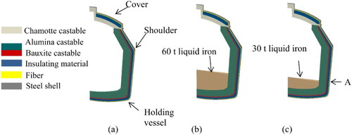
Table 1. The main chemical composition and typical physical properties of the materials used for the working and insulating linings.
The channel induction furnace may serve for one to one and half years before the entire refractory lining requires changing. The present work only considered the 9 days of preheating the new linings, 3 days for the casting process and 2 days for the holding process. More specifically, the hot face temperature of the working lining increased linearly to 1200°C in 9 days during the preheating. After preheating, the furnace was ready to hold the liquid iron. The casting then continued in shifts before the weekend. The mass of liquid iron varied; hence, another simplification was made for the modelling process. The liquid iron mass was assumed to be 60 t during the casting; only 30 t of liquid iron remained in the furnace for the weekend. The hot iron instantly contacted the working lining. The melt temperature remained constant at 1500°C due to the automatic induction melting functionality.
The initial temperature of the channel induction furnace and ambience was 25°C. For the interface between the fluid and the solid, a heat transfer coefficient function was used, representing radiation and convection. This is termed film condition in ABAQUS. For gaps, which open during service and are crossed by the heat flux, a heat transfer coefficient allowing for radiation and convection was defined. This heat transfer coefficient was named thermal conductance in ABAQUS. During the casting and holding periods, a surface radiation condition with emissivity of 0.77 was applied for the space above the liquid iron [Citation6].
The displacement of the linings perpendicular to the coaxial vertical boundary planes of the sector was fixed in the circumferential direction and this assisted in the realisation of the symmetrical configuration of the furnace. The shoulder of the furnace (indicated in ) was constrained in all directions. All other parts of the furnace were self-restrained. The thermomechanical simulation allowed for creep that occurred in the working lining, while the residual refractory lining and steel shell behaved elastically, given that they usually experience low temperatures.
von Mises creep model and creep characterisation
The classical von Mises creep model, which is independent of hydrostatic pressure, was applied in the present work. Two terms of creep strain are often applied to characterise the creep deformation of materials. One is the creep strain (i, j = 1, 2, 3) in the respective stress direction, which can be integrated by the corresponding creep rate
with respect to time following equation (1):
(1) The other one is the equivalent creep strain
, which is an absolute and accumulative value of the global creep strain increment with respect to time. The equivalent creep strain can be expressed by equation (2)
(2) where
is the equivalent creep strain rate.
For the case of the classical creep model, the creep strain rate matrix can be calculated according to equation (3)(3) where s is the deviatoric stress, q is equal to
and σ is the principal stress [Citation6]. After decomposition along the principal directions, the principal creep strain rates are further given as
(4) where p equals
.
A special example was used to illuminate the significance of creep strain terms. When a reversed uniaxial loading, namely a tension–compression cycle, was applied, the absolute value of principal creep strain was reduced. This quantity indicates the length change due to creep in the respective direction. In contrast, the equivalent creep strain value indicates that the creep effect is irreversible and additive. Indeed, the refractory linings frequently experience more complicated thermomechanical loads. Thus, the term of equivalent creep strain was used in the present paper and indicated the global creep response of the refractories, which is denominated as CEEQ in ABAQUS [Citation6].
Specimens of E1 were dried at 110°C for 24 h after vibration casting in the laboratory, and then fabricated into cylinders of Ø 35 mm × 70 mm. Creep measurements were accomplished by means of an advanced compressive creep testing device [Citation7]. For each test, the temperature was kept constant and the creep curve was documented including the initial loading procedure. The Norton–Bailey strain hardening equation was applied to characterise the creep behaviour(5) where K is a temperature function, n is the stress and a is the creep strain exponent. The creep parameters were inversely identified and are shown in .
Table 2. Norton–Bailey creep law parameters of E1 at 1200–1500°C [Citation7].
Results
To display the temperature evolution with respect to the process time, the temperatures at the location A of the steel shell () are plotted in (a). It is evident that the temperature changed slightly during the holding period implying that the heat diffusion approached equilibration. lists the mean steel shell temperatures and their standard deviations. The temperature decrease is the mean temperature difference between the new lining and the reference temperature divided by that of the reference. A similar calculation was executed for the energy-saving comparison. As shown in , the mean temperature of the steel shell decreased by 7–10% (13–16°C) with a subsequent energy savings of up to 15%, based on the application of the insulating material A4.
Figure 2. (a) Temperature evolution in the steel shell with respect to the process time; (b) temperature distribution after a 2-day holding period along the thickness from the wear lining to the steel shell.
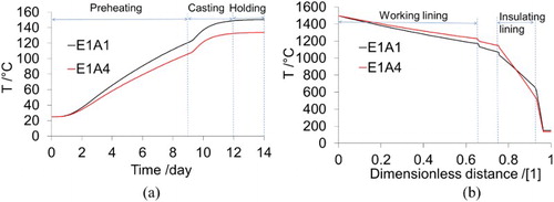
Table 3. Mean temperature and heat loss comparison in the steel shells.
The temperature profile of the furnace at the end of a 2-day holding period is also plotted in . The dimensionless distance is the distance from the working lining hot face divided by the total thickness of lining. As seen in (a), the cold end temperature of the working lining when using the insulating material A4 was 1228°C, compared with 1169°C for the reference temperature. The hot face of monolithic material A4 reached 1148°C, which was 79°C higher than that of the reference. However, this temperature was still lower than the critical value for the safety design of channel induction furnace linings of 1200°C.
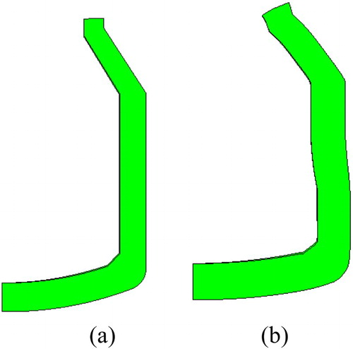
Creep occurred in the working lining during the preheating and service. (a–c) indicates the equivalent creep strain (CEEQ) distribution for the lining concept E1A1. At the end of preheating, creep took place at the hot face, owing to the inferior creep resistance of non-pre-fired monolithic materials during the first temperature exposition [Citation7]. At the end of casting period, significant creep occurred at the hot face of the working lining, while the entire working lining experienced evidence of creep. Additionally, the maximum equivalent creep strain occurred around the liquid iron/monolith/atmosphere interface and bottom corner. At the end of the holding period, one can find that the region experiencing the maximum CEEQ was the same as that at the end of casting period. By comparing the geometries before preheating and after service, a relative deformation of the upper and lower sections of the monolith was noticeable in the radial direction, as indicated in . This deformation caused a shear load in the region around the liquid iron/monolith/atmosphere interface and contributed to the considerable creep.
Figure 3. Equivalent creep strain distribution in the working lining of the lining concept E1A1 at the end of (a) preheating, (b) casting and (c) holding.
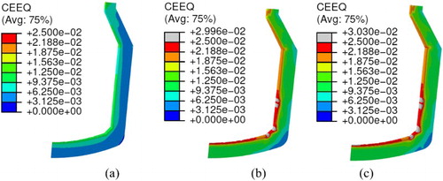
Figure 4. Relative displacement of the working lining (a) before preheating and (b) after service (scale factor: 20).
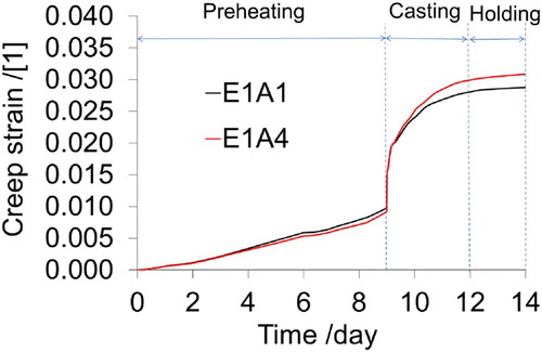
Following the above results, the location of the working lining constituting the liquid iron/monolith/atmosphere boundary was chosen to compare the equivalent creep strain evolution within the lining concepts E1A1 and E1A4 with respect to the process time. As seen in , creep occurred at the very beginning of the preheating stage. This is due to the inferior creep resistance of the castable E1 during the first temperature exposure; and thus, a linear interpolation application of the creep parameters from high temperatures to the ambient temperature for the simulation. Furthermore, a sharp increase in the equivalent creep strain occurred at the beginning of the casting period. Afterwards, the increase of the equivalent creep strain was more moderate. Near the end of the holding period, the equivalent creep strain was nearly constant. The proposed lining concept E1A4 showed slightly higher creep strains at the late stage of casting and during holding. As seen from (b), the temperature in the working lining close to the hot face in the case of E1A4 is higher than that in the case of E1A1. In 1400–1500°C, creep resistance of the dense castable E1 decreased significantly with increasing temperature [Citation7]. This accounts for the creep strain increase of the investigated region during holding in the case of E1A4. Nevertheless, the relative difference between ultimate equivalent creep strains of two lining concepts at this location was just 7.3% and can be neglected. In addition, at the hot face of the working lining, a maximum circumferential compressive stress of ∼20 MPa was observed during the preheating period. Additionally, a maximum circumferential tensile stress of ∼69 MPa was predicted at the beginning of the casting period for both concepts.
Figure 5. Equivalent creep strain evolution of the working lining for the liquid iron/monolith/atmosphere boundary with respect to the process time.
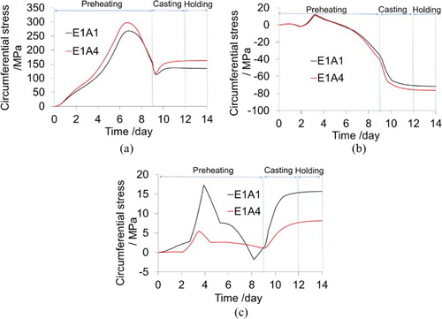
Applying monolithic material with a strong heat insulating effect might also negatively impact the residual refractory lining. To assess this, shows the circumferential stress with respect to the process time at the hot faces of safety and insulating linings and the cold end of the steel shell. The chosen locations for plotting data in were at the height of the bath level for the 30 t of liquid iron (letter A in (c)). The maximum tensile stress at the steel shell occurred during the preheating period. This stress amounted to 297 MPa for the new lining concept E1A4, which was 11% higher than that of E1A1. The tensile stress at the steel shell decreased afterwards due to the creep of the working lining. In the case of the safety lining, compressive stress was primarily present and the stress difference between two lining concepts was insignificant. The insulating lining underwent tensile stress primarily in the circumferential direction. This stress was attributed to the shrinkage of the monolithic insulating material and the outward radial displacement caused by the thermal expansion of working and safety linings [Citation5]. The higher tensile stress in the light weight material A1 resulted from its high Young’s modulus, as shown in . A4 experienced lower tensile stresses in service, and the ratio of tensile stresses in A1 and A4 approximates 1.9 at the end of holding. It needs to mention that the vertices at the (b) and (c) were caused by the thermal shrinkage of the monolithic materials during the first temperature exposure.
Figure 6. Circumferential stress evolution with respect to the process time: (a) cold end of steel shell, (b) hot face of permanent lining and (c) hot face of insulation lining.
Conclusion
The previous research demonstrates an efficient optimisation approach for extensive refractory lining concepts, adopting FE elastic modelling and orthogonal array methods. The investigation yielded a candidate for a lining concept that contains virtually the same in-use dense castable as the working lining as well as a new lightweight monolith with a stronger thermal insulating effect for the insulating lining [Citation5]. Further inelastic FE modelling was performed allowing for creep occurrence in the working lining leading to a better understanding and improved evaluation of furnace lining behaviour. The thermal and thermomechanical results confirmed that the above proposed lining concept is applicable. It is worth mentioning that for more complicated conditions such as the joint opening of the brick lining, a lining concept optimisation procedure might be necessary to directly utilise the inelastic FE method with the orthogonal array design.
ORCID
D. Gruber http://orcid.org/0000-0002-6801-4324
Additional information
Funding
Related Research Data
References
- Gandhewar VR, Bansod SV, Borade AB. Induction furnace – a review. Int J Eng Technol. 2011;3(4):277–284.
- Bebber H, Shah BG. Induction furnaces for copper and copper alloy melting. Seminar Proceedings of Copper and Cooper Alloys Melting & Casting for Further Working; Mumbai, India; December 2000.
- Spitz W, Eckenbach C. Channel-type versus coreless induction furnaces. Aluminum. 2013;1–2:46–49.
- Ambade RS, Komawar AP, Paigwar DK, et al. Energy conservation in an induction furnace: a new approach. Int J Adv Technol Eng Sci. 2015;3(s1):153–160.
- Jin S, Gruber D, Harmuth H, et al. Optimisation of monolithic lining concepts of channel induction furnace. Int J Cast Metal Res. 2014;27(6):336–340. doi: 10.1179/1743133614Y.0000000111
- ABAQUS Analysis User’s Manual Release 6.12, 2012.
- Jin S, Harmuth H, Gruber D. Compressive creep testing of refractories at elevated loads – device, material law and evaluation techniques. J Eur Ceram Soc. 2014;34(15):4037–4042. doi: 10.1016/j.jeurceramsoc.2014.05.034