
ABSTRACT
Physicochemical behaviour of the pellets, sinters and its mixture (60% pellets: 40% sinter) is investigated by a series of smelting and quenching experiments. For all ferrous raw-material beds, three distinct stages of bed shrinkage occur due to indirect reduction, softening and melting. However, the characteristic nature (displacement, temperature and permeability) differ with the ferrous raw-material type. In mixed ferrous bed, the first and third stages are found to be controlled by the pellets (individual particle shrinkage) and sinter (slow melting rate), respectively. Second stage behaviour is initially observed to be close to the pellet and later to that of sinter. In mixed bed (upto 1505°C), the interaction between the pellet and sinter is limited to the interface only. The sinter slag is observed to control the melting and dripping properties of the mixed bed.These results gives an understanding of individual and mixed burden behaviour under blast furnace conditions.
Introduction
The iron produced from the blast furnace route is expected to continue to be utilised for steel production [Citation1]. The blast furnace ironmaking process is energy-intensive, and an increase in process efficiency is essential for sustainability. Owing to the counter-current nature and packed bed characteristics of the ironmaking blast furnace, the productivity can be enhanced by improving the gas permeability.
It is well known that at the cohesive zone of the blast furnace, significant resistance to the gas flow occurs due to the softening and melting of the ferrous raw materials [Citation2]. Therefore, to minimise the resistance, a small difference between the softening and melting temperature of the ferrous burden is desired [Citation2,Citation3]. This can be achieved by the proper selection of the ferrous raw material for metal production [Citation4,Citation5].
In the blast furnace, a mixture of two or three types (iron ore, pellets and sinter) of ferrous materials is generally used for the metal production. The mixing proportions of these ferrous raw materials are adjusted based on the chemical and economic balance. Generally, olivine fluxed pellets are used for their superior properties [Citation6,Citation7] and lower slag volume operations [Citation8]. The iron ore sinter making serves as an excellent medium to recycle many dusts, sludge, etc., which is generated in an integrated steel plant. Thus, iron ore sinter making is common in many steel plants globally. Moreover, the iron ore sinter is added to improve the physical (strength) and chemical (basicity) property of the ferrous raw material bed in the blast furnace [Citation9]. Furthermore, the ferrous burden chemistry and mixing proportion are varied to adjust the slag composition, which controls the metal composition (carbon, silicon and sulphur).
This ferrous burden, when mix charged, can behave differently due to the different shape, preparation history and chemistry. Various studies have been performed to understand the effect of basicity on the physicochemical properties of the individual pellets or sinter burden [Citation10–14]. However, only a few have reported the behaviour of pellet and sinter mixed bed [Citation11].
In the present study, a thorough investigation is performed under simulated blast furnace conditions to understand the behaviour of the ferrous burden of pellets, sinter and its mixture.
Materials and methods
Raw materials
Commercially supplied iron ore pellets and sinter of size range 10–13 mm are utilised in the present study. Comparable to the utilisation in the industrial blast furnace, two types of olivine fluxed pellets (types 1 and 2) and one type of iron ore sinter are mixed in 40:20:40 ratio to form a ferrous raw material bed. Coke of 20–25 mm size range is utilised as regular coke. The chemical analysis of the ferrous raw materials is given in . The ferrous raw material (pellet, sinter and mixture) layer is sandwiched between the two regular coke layers.
Table 1. Chemical analysis of the ferrous raw materials (XRF).
Experimental methods and conditions
The experiments were performed on the Reduction Softening and Melting (RSM) apparatus under simulated blast furnace conditions. Detailed information about the experimental set-up is given in the references [Citation15–17]. Smelting and quenching tests are performed to understand the behaviour of the ferrous raw material bed. For individual burden type testing, considering similar pellet chemistry, test with pellet type 1 was conducted and the behaviour of pellet type 2 is assumed identical to that of pellet type 1.
Smelting experiments
High temperature (20–1550°C) experiments are carried out in the RSM to realise the smelting of the ferrous raw material. The thermal and gas profile followed during the smelting experiments are given in . Smelting tests are performed for pellet (type 1), sinter and ferrous burden (mixed pellet and sinter).
Table 2. Thermal and gas profile followed during the experiments.
Quenching experiments
The quenching temperature for the sample bed was decided upon after a series of smelting experiments. In order to understand the prime reason for the ferrous bed melting, samples are heated and quenched close to the bed melting temperature (Tm). The iron ore pellet bed and ferrous burden (pellet and sinter mixture) are quenched at 1480 and 1505°C, respectively. In order to investigate the internal state of the sinter bed at high temperature, it is quenched at 1550°C. After cooling, the sample crucibles are cast using cold mounting resin and cut vertically into two halves for further analysis.
Analysis
The cross-sections of the selected ferrous raw materials are visualised by using an optical microscope (Keyence VHX-5000). The chemical analyses of the pellets and sinter are measured with XRF (X-ray fluorescence, Panalytical, Axios Max), and the results are given in . The dripped samples collected in the cup are removed. After that, a portion of the sample is pulverised and magnetically separated (slag and metal). The slag (non-magnetic portion) is analysed with XRF for the present elements and the metal (magnetic portion) is analysed for the carbon content with LECO (Carbon–Sulphur analyser, CS744). The elemental distribution present in the quenched sample is investigated using Energy Dispersive X-ray analysis (SEM-EDS, JSM-IT100). For the carbon analysis in the dripped metal, the combustion infrared detection technique (LECO) is employed. The thermodynamics software package ‘Factsage 7.0’ is utilised to calculate the phase diagrams.
Results and discussion
Typical characteristics of the ferrous bed
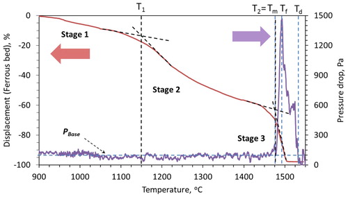
In the ferrous raw material bed, three distinct stages of contraction occur [Citation3,Citation18]. Generally, the three principal phenomena responsible for bringing these three stages are; indirect reduction, softening and melting, respectively. Correspondingly, high-pressure drop regimes occur due to the bed melting (Tm), flooding (Tf) and dripping (Td) of the ferrous raw materials (). Definitions of various characteristic phenomena derived from the bed contraction and gas pressure drop across the sample bed are discussed in our previous articles [Citation3,Citation19].
Figure 1. Characteristic behaviour of the iron ore pellet (type 1) bed under blast furnace conditions.
Characteristics of pellet bed
Pellet bed shrinkage and permeability
The characteristic pellet (type 1) bed contraction and pressure drop behaviour under blast furnace conditions are shown in . In the first stage, about 14% of bed contraction (D1) occurs (). The first stage of contraction occurs primarily due to the shrinkage of individual pellets, as a result of the gaseous (indirect) reduction. Then the iron starts to form on the pellet surface due to the complete reduction of iron oxide. This proceeds topo-chemically on the individual pellets [Citation18,Citation20]. Then as the temperature increases, sintering within and among the pellets occurs [Citation18,Citation21,Citation22]. These make it difficult for the reducing gas to flow in the interior of the bed and cause the melting of FeO-rich regions inside the pellets. Consequently, the pellets start to soften under the load (stage 2) [Citation23]. Then the melting starts based on the carburisation level achieved on the pellet shell (Tm). This is noted by a drastic increase in the rate of bed shrinkage to start the third stage of bed contraction ().
As described, the second stage of bed contraction occurs due to the localised liquid formation, which results in the pellet softening [Citation23]. The formed liquid is mostly entrapped in the pellet core and in the micropores present on the pellet. Consequently, the inter-pellet voids are available for the gas flow. As a result, no significant rise in the resistance to the gas flow occurs during the second stage of bed contraction. As in the third stage, when the pellet melting and breakout start, these inter-pellet voids begin to get filled up by the liquid (iron and slag) [Citation24]. Consequently, a sharp rise in the pressure drop occurs due to the pellet melting at about 1480°C (). The formed liquid starts to flood (at Tf) the pellet bed, to reach the maximum pressure drop and later drip out of bed.
Quenched pellet bed
Following the start of the melting, the pellet bed (type 1) is quenched at 1480°C. The quenched sample bed is cast and cut into two halves for characterisation. Melting in the pellet bed is observed to start from the point of contact between the pellet and coke, which is at the layer interface [Citation19]. The iron present as the pellet shell carburises first by its direct contact with the coke to melt later. This continues to cause the layer-wise melting and dripping of the pellet bed [Citation19,Citation25].
As a result, after the start of melting (Tm), the high-pressure drop regime continues to remain high until the liquid downward flow and dripping starts from the bed (). Then, after significant liquid draining out of bed, the pressure drop value recovers back to the PBase value at the dripping temperature (Td) (). A detailed characterisation of the quenched pellet only bed is presented in our previous articles [Citation3,Citation19].
Characteristics of sinter bed
Sinter bed shrinkage and permeability
The characteristics of the iron ore sinter bed contraction and pressure drop under simulated blast furnace conditions are shown in . In the first stage, a limited bed contraction (3.4%) occurs in the sinter bed. Compared to the iron ore pellets, the sinter has a stronger and more stable structure [Citation26], which results in limited shrinkage in the first stage temperature range. Additionally, due to its irregular structure, the sinter does not shrink uniformly across the bed to show less bed contraction.
Figure 2. Characteristic behaviour of iron ore sinter bed under blast furnace conditions.
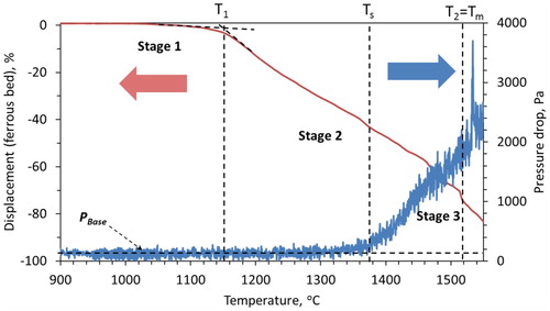
Now, with the increase in temperature and reduction degree, the metal formation occurs in the sinter. Then, due to the heat and pressure (load), particles start to get compacted among each other (second stage of contraction). Thereafter, the FeO-rich region melts, which starts to hinder the gas flow through the sinter bed. As a result, the pressure drop gradually starts to increase above the PBase value after bed softening temperature (Ts = 1375°C).
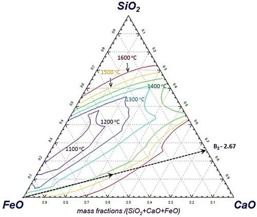
As the reduction reaction proceeds further, the sinter gets leaner in the FeO content. Consequently, the melting point of the slag forming mineral increases [Citation27]. A typical effect of the decrease in FeO content, which increases the liquidus temperature of SiO2–CaO–FeO–(5%)MgO type slag system is evident from . From sinter, the fluxes and gangue start to precipitate out [Citation26]. Correspondingly, the viscosity of the melt increases [Citation10,Citation27,Citation28]. This continues until the start of iron melting in the bed at ∼1520°C, which is noticed by a sharp increase of pressure drop across the bed. The molten metal along with slag and precipitated solid particles (slag and gangue) forms a semi-fused mass, which exerts a very strong resistance against the gas flow. Consequently, the pressure drop continues to increase even after the bed melting temperature (Tm). As there is no liquid dripped out of bed, no significant change in the bed contraction is observed in the third stage. After reaching 1550°C, the sample bed is quenched and afterward cut vertically in two halves to visualise and characterise the internal bed state (Section: Quenched sinter bed).
Figure 3. SiO2–CaO–FeO-(5%) MgO phase diagram with slag liquidus temperature projections (Factsage).
Quenched sinter bed
In order to investigate the impermeable nature of the sinter bed at high temperature, it is quenched at 1550°C. shows the internal state of the quenched sinter bed.
Figure 4. Photographs of two halves of quenched iron ore sinter bed at 1550°C.
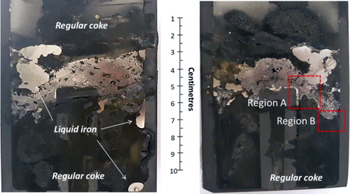
A large chunk of a fused material mass is apparent between the coke layers in the photograph. The shiny region of liquid iron above and below the fused mass can be seen in the bed. Optical microscopy is performed on this selected metal region, which reveals the presence of iron in the form of grey cast iron (2.5–4.0 wt-% C, 1–3 wt-% Si) [Citation29]. This is formed due to the carburisation of the liquid iron, which is in contact with the coke present in the top layer. However, such a microstructure is not observed in the iron nuclei present inside the fused mass () due to lower iron carburisation.
Figure 5. Microstructure of the selected regions from quenched iron ore sinter bed.
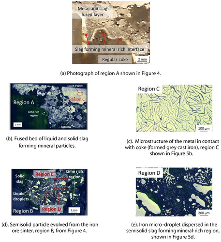
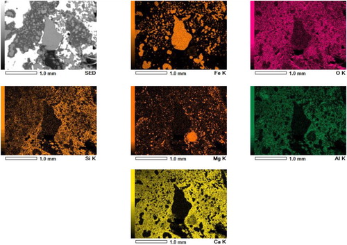
Selected regions of the quenched bed are shown in . The interface rich is slag forming mineral between the regular coke and the fused layer is apparent from region A ((a)). The solid slag and disperse liquid metal is evident from region B ((d,e)). EDS scan of a section in region B further confirms the distribution of calcium-rich slag forming mineral around the metal droplet (). At high temperature, this creates a viscous semi-fused liquid metal and solid slag forming mineral-rich region to resist the dripping [Citation11] and gas flow.
Figure 6. EDS scan of a selected region E from quenched iron ore sinter bed (). An entrapped liquid iron droplet present inside the bed.
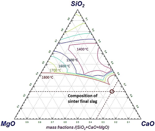
An estimation was performed with Factsage to calculate the amount of liquid slag at 1550°C. The results reveal that only ∼35% of the slag forming minerals (assumed FeO is completely reduced to iron) are in the liquid state at 1550°C. Furthermore, estimation shows that for the complete melting of the slag forming minerals (SiO2–CaO–MgO–(6.25%)Al2O3) present in the sinter, a very high temperature of about 1940°C is required (). This is the prime reason for the presence of solid mineral particles with molten iron in the quenched bed. This forms a fused mass of metal and slag to strongly resist (Svalue = 0.65 MPa .°C) the gas flow across the bed.
Figure 7. Phase diagram (SiO2–CaO–MgO–(6.25%) Al2O3) with liquidus temperature projections.
Characteristics of mixed ferrous burden (pellet and sinter mixture)
Ferrous bed shrinkage
The ferrous burden is a mixture of iron ore pellets (40% pellets type 1:20% pellets type 2) and sinter in 60:40 ratio. The chemistry of the ferrous burden is given in .
The ferrous bed contraction is shown in . During the experiments under simulated blast furnace conditions, similar to pellet only and sinter cases, three distinct stages of the bed contraction are observed. In the first stage, the mixed bed shows the contraction properties in between the sinter and pellet only bed. However, the shape of the curve in this region appears close to the case of iron ore pellet only bed (). This indicates that the bed contraction in the first stage occurs predominantly due to the shrinkage of the individual pellets in the bed, which is a result of the indirect reduction reactions [Citation3,Citation18].
Figure 8. Bed contraction profile for ferrous raw materials.
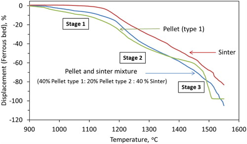
Then the second stage of bed contraction starts with the rapid shrinkage similar to that of the pellet only bed (). This occurs due to the start of pellet softening and sintering (within and among each other). Thereafter, the bed contraction curve changes its nature from pellet type to sinter type to continue the contraction with a gradual rate. Then, the second stage ends at ∼1505°C (T2) with a bed displacement of 81% (D2). The bed melting temperature (T2) is higher by 25°C compare to the pellet only case (1480°C). This is primarily due to the presence of the sinter in the ferrous bed, which has comparatively weak reducibility and melting properties. Furthermore, a high degree of shrinkage occurs in the ferrous bed due to the poor strength of the sinter at high temperature.
For the mixed ferrous burden, the shift from the second stage to the third stage is gradual, which is contrary to the pellet only case. The bed contraction characteristic at the third stage is similar to that of the sinter only bed (). This indicates that when the sinter and pellet are mixed charged, the bed properties in the first stage are dominated by pellets and the third stage is dominated by sinter. However, in the second stage, the bed shrinkage profile is controlled by pellets initially then it is governed by the sinter softening behaviour.
It is known that the rate of pellet bed melting (stage 3) is higher than that of the sinter bed (). The iron ore pellets contain a low amount of impurities and fluxes. Thus, the melting temperature of the pellet is controlled by the level of iron (pellet shell) carburisation [Citation19]. However, the sinter contains a high amount of gangue (SiO2 and Al2O3) and fluxes (CaO and MgO) (), which certainly affects its melting behaviour. Among these, the melting of the calcium-rich oxide (CaO) is known to occur at very high temperatures [Citation30] (). Thus, when the melting of iron from pellets and sinter starts, the flow of liquid is retarded due to the presence of the solid slag forming mineral particles ((a)). Consequently, the rate of mixed bed melting is more gradual than that of the pellet only case.
Ferrous bed permeability
The gas permeability profile during the softening and melting of the ferrous burden (pellet and sinter mixture) is shown in . The pressure drop across the bed starts to increase from PBase at 1375°C, which is close to the bed softening temperature (Ts) of the iron ore sinter (). Thereafter, the pressure drop continues to increase gradually. However, due to the presence of pellets in the bed, the magnitude of the pressure drop is observed to be lower than the case of sinter only bed. As discussed earlier, the slag in the pellet is mostly entrapped in the micropores present in the metallic shell, and it is distributed in the core [Citation22]. Consequently, at the time of bed softening, the interstitial voids around the pellets are open for the gas flow across the bed.
Figure 9. Measured profile of pressure drop for ferrous raw materials bed under simulated blast furnace conditions.
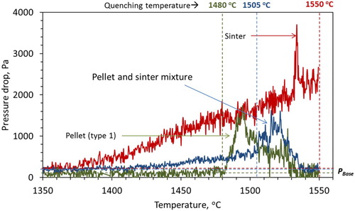
However, when the pellet melting starts, the slag and metal fill-up the inter-particle voids to mark the drastic increase in the pressure drop. The ferrous bed melting is observed to start at 1505°C, which is in between the pellet and sinter only bed melting temperature of 1480°C and 1520°C, respectively. In our previous article, it is discussed that the carburisation achieved on the reduced iron controls the bed melting temperature. Now, considering the poor gas permeability compared to the pellet only bed and higher permeability compared to the sinter only bed, the level of iron carburisation is expected to be in between the pellet only and sinter only bed. Furthermore, two regimes of high-pressure drop are observed for the mixed burden after the start of bed melting, which indicates the melting of two different burden types. Then once the PPeak is achieved, the pressure drop is observed to decrease similar to the case of pellet only bed. These suggest that similar to the pellet only bed [Citation19], layer-wise carburisation, melting and dripping occurs from the ferrous burden bed.
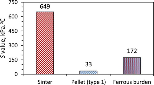
Resistance to the gas flow (S-value)
During softening and melting of the ferrous raw materials, the pores in the bed are filled up to exert resistance against the gas flow. As a result, the pressure difference across the bed increases [Citation31]. The complete area under the pressure drop curve (S-value) represents the total resistance exerted to gas flow during the softening and melting of the ferrous burden [Citation3].
The S-value for the pellet only, sinter only and the mixed ferrous burden is shown in . Clearly, the pellet only bed shows the lowest S-value. Mixing the pellets with sinter has increased the gas permeability of the ferrous bed. The principal reason for such behaviour is discussed in the next section (Quenched ferrous bed).
Figure 10. Measured S-value for different burden type (S-value; a measure of resistance to the gas flow during softening and melting of the ferrous burden).
Quenched ferrous bed
Photographs of the ferrous burden (pellet and sinter mixture) quenched at the start of the bed melting (Tm = 1505°C), are shown in . A high degree of compaction achieved on the ferrous bed is evident from the photograph. The squeezed and deformed top layer of the ferrous burden is apparent (). The ferrous burden particles present in other layers are observed solid and able to hold their shape. The iron ore sinter occupies the interstitial space around the pellets to close the inter-pellet voids. Additionally, close contacts among the sinter and pellets are observed (). However, no macroscopic melting is seen in the quenched bed.
Figure 11. Two halves of the ferrous burden (pellet and sinter mixture) quenched at 1505°C (P-Pellet, S-Sinter, RC- Regular coke).
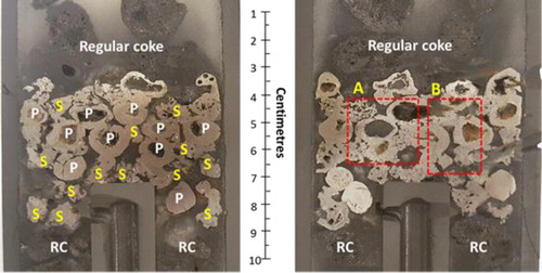
Sections (regions A and B) of the quenched bed are selected to microscopically visualise the internal state of the ferrous burden ( and ). The close contact among the ferrous burden particles can be seen in . A clear interface is observed between the sinter and pellets ().
Figure 12. Selected section (region A) from the ferrous bed quenched at 1505°C ().
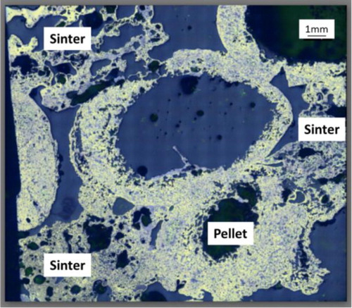
Figure 13. SEM-EDS micrograph of an interface between pellet and sinter.
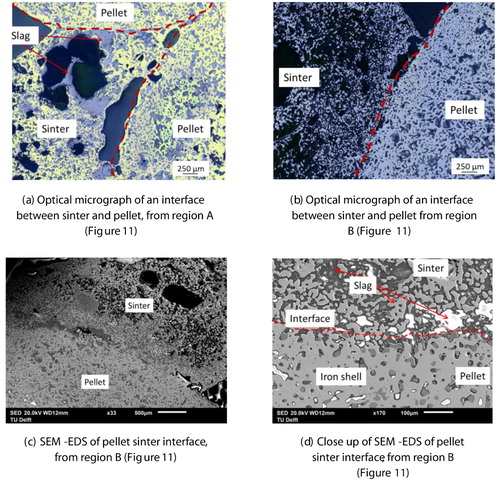
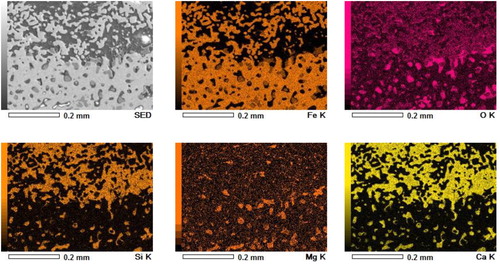
To investigate the extent of interaction between the pellet and sinter, an SEM-EDS analysis is performed at a selected interface (). A clear difference in the present phases between the sinter and pellets is observed ((d) and ). In the pellet region, along with the dense reduced iron layer, a slag rich in magnesium and silicon (olivine-type slag) is observed. In the sinter region, dispersed iron nuclei in calcium and silicon-rich slag matrix can be seen. These indicate that the interaction between the sinter and pellet is limited to the surface region only. No bulk melting and intermixing between the sinter and pellets is observed till the bed melting temperature (1505°C). However, it is noted that the surface pores of the sinter and pellets are blocked by slag. The close contact and sintering among the ferrous burden prevent the slag to flow away from the interface [Citation14]. Furthermore, the high melting temperature of the slag forming minerals present in the sinter restricts the interaction limited to the surface region only.
Figure 14. SEM-EDS elemental scan at the of the pellet-sinter interface ((d)).
As discussed, in the pellet bed, layer-wise melting occurs. Similarly, in the quenched mixed ferrous bed, the iron ore pellets present in the top layer are observed to be significantly deformed (). However, due to the heterogeneous shape of sinter particles, the deformation is not apparent. Nevertheless, similar to the pellet-only burden, in the mixed ferrous burden, layer-wise carburisation and melting are also expected to occur.
Additionally, the melting of the pellets is faster compared to the sinter burden (). As discussed earlier, due to low impurity content in pellets, melting and dripping properties are controlled by iron carburisation. On the other hand, the sinters are rich in gangue (SiO2 and Al2O3) and flux (CaO and MgO) contents (). Among these, the melting of the CaO rich oxides is known to occur at higher temperatures [Citation30]. Thus, when the melting of reduced iron in the sinter starts, the flow of liquid is restricted by the presence of solid slag forming mineral particles. Consequently, the melting rate of the sinter is retarded. Thus, when ferrous burden (sinter and pellet) are mixed, melting and dripping behaviour is controlled by the sinter present in the bed.
Dripped liquid
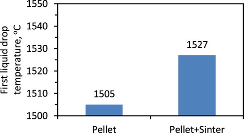
First liquid drop
The liquid drips out of the sample crucible and gets collected in the cups located in the sample receiver in the RSM. The temperature (Txf) of the first liquid drop is recorded after visualising the event from the glass window located at the receiver. The liquid is observed to drip in the form of rivulets. The inconsistency in liquid dripping could also be a result of the liquid (slag and metal) and solid coke interaction [Citation28,Citation32]. For example, the liquid iron turns from wetting (50° for 0 wt-% C) to non-wetting (130o for 5 wt-% C) with an increase in the carbon concentration [Citation32].
Liquid dripping from the pellet only bed starts before the pellet and sinter mixed bed (). In addition, from the sinter only bed, no liquid dripping is observed during smelting up to 1550oC. This further confirms that the presence of the sinter in the mixed bed retards the rate of melting and dripping of the ferrous burden.
Figure 15. Temperature when the first liquid drop was observed.
Drip liquid chemistry
In the blast furnace, the liquid drips out of the cohesive zone to flow through the active coke zone. While the melts flow over the coke, many vital reactions occur, such as the direct reduction of FeO-rich slag, liquid iron carburisation [Citation11], sulphur and silicon transfer [Citation2]. Furthermore, the dripping pattern of the liquid is also strongly linked to the gas intake capacity and, therefore, to the productivity of the blast furnace [Citation2]. Thus, it is important to understand the effect of burden type on the dripped liquid chemistry.
In the smelting experiment, the molten iron carburises when it flows across the regular coke layer [Citation19]. This occurs during the third stage of bed contraction. Now, considering a faster rate of bed contraction for pellet only bed, lower iron carburisation was expected. However, it is found vice versa as it is controlled by the amount and type of the slag forming mineral in the ferrous burden (). In the pellet and sinter mixed bed due to the high content of the slag forming mineral, the interaction between the metal and the coke is restricted to cause lower iron carburisation.
Figure 16. Effect of burden type on the iron carburisation.
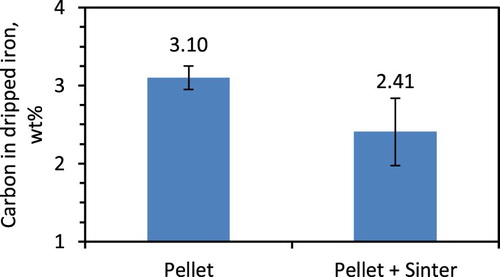
Additionally, in the pellet and sinter mixed bed due to higher interaction between the slag forming mineral and coke (due to slow dripping rate), low FeO content is observed in the dripped slag. On the other hand, in the pellet only bed due to faster rate of liquid melting and dripping lower interaction between the slag and coke occurs, to result in high FeO content in the dripped slag (). Furthermore, an apparent difference in the slag basicity is observed between the dripped slag from these ferrous bed. Due to the presence of sinter, CaO rich slag is observed dripping from the mixed beds.
Table 3. Dripped slag compositions (wt-%).
Conclusions
The physicochemical behaviour of pellets, sinter and its mixture (60% pellet:40% sinter) is investigated under simulated blast furnace conditions in the reduction, softening and melting (RSM) apparatus. After a series of smelting and quenching experiments, the following conclusions can be drawn.
1. Pellet bed contraction evolves through three distinct stages. The first stage of the bed shrinkage occurs due to the indirect reduction. The second stage of the bed contraction occurs because of the softening and sintering of the pellets. However, due to the presence of interstitial voids in the reduced pellet bed, gas permeability is not hampered until the start of bulk melting.
The third stage is drastic, which occurs as a result of the melting and dripping of the pellets. Poor gas permeability is observed during the melting and dripping of the pellets.
2. In the sinter bed, the three stages of bed contraction also occur. However, at high temperature (above 1375oC), sinter particles form a semi-fused mass to cause very high resistance to the gas flow. This occurs due to the sintering, softening and partial melting of the sinter particles. No liquid dripping was observed from the sinter only bed up to 1550oC.
3. In the pellet (60%) and sinter (40%) mixed ferrous bed, contraction is also realised via three distinct stages. The bed contraction characteristics of the first and third stage are observed to resemble the pellet only and sinter only bed, respectively. The second stage shows mixed properties, initially similar to the pellet only bed, later more to that of the sinter only bed.
4. Sintering among the mixed ferrous burden (pellet and sinter) is observed to restrict the gas flow, which causes a gradual loss of permeability in the bed. Then, until the start of bed melting (1505oC), the interaction between the sinter and pellet is limited to their interface region only. No bulk intermixing and melting is realised.
5. In the mixed ferrous bed, the slag from the sinter retards the rate of bed melting to control the interaction between the ferrous (metal and slag) liquid and the solid coke.
These results provide an insight into the physicochemical behaviour of the pellets, sinter and it’s mixture under the blast furnace operating conditions.
Acknowledgements
This research was carried out under project T41.5.13490 in the framework of the research programme of the Materials innovation institute (M2i) supported by the Dutch Government and metallurgical industry (Tata Steel). The project was conducted at the Department of Materials Science and Engineering (MSE) of the Delft University of Technology in the Netherlands.
Disclosure statement
No potential conflict of interest was reported by the author(s).
Additional information
Funding
References
- Birat JP. Global technology roadmap for CCS in industry: steel sectoral report. Amsterdam2010.
- Biswas AK. Principles of blast furnace iron making – theory and practice. Brisbane: Cootha Publishing House; 1981.
- Gavel DJ, Adema A, van der Stel J, et al. Effect of nut coke addition on physicochemical behaviour of pellet bed in ironmaking blast furnace. ISIJ Int. 2019;59(5):778–786. doi:10.2355/isijinternational.ISIJINT-2018-580.
- Gavel DJ. A review on nut coke utilisation in the ironmaking blast furnaces. Mater Sci Technol. 2017;33(4):381–387. doi:10.1080/02670836.2016.1183073.
- An XW, Wang JS, Lan RZ, et al. Softening and melting behavior of mixed burden for oxygen blast furnace. J Iron Steel Res Int. 2013;20(5):11–16. doi:10.1016/S1006-706X(13)60090-4.
- Kemppainen A, Ohno K, Iljana M, et al. Softening behaviors of acid and olivine fluxed iron ore pellets in the cohesive zone of a blast furnace. ISIJ Int. 2015;55(10):2039–2046. doi:10.2355/isijinternational.ISIJINT-2015-023.
- Kaushik P, Fruehan RJ. Mixed burden softening and melting phenomena in blast furnace operation Part 3 – Mechanism of burden interaction and melt exudation phenomenon. Ironmak Steelmak. 2007;34(1):10–22. doi:10.1179/174328106X118161.
- Semberg P, Andersson C, Björkman B. Interaction between iron oxides and olivine in magnetite pellets during reduction to wustite at temperatures of 1000–1300 °C. ISIJ Int. 2013;53(3):391–398. doi:10.2355/isijinternational.53.391.
- Loo CE, Matthews LT, O’dea DP. Lump ore and sinter behaviour during softening and melting. ISIJ Int. 2011;51(6):930–938. doi:10.2355/isijinternational.51.930.
- Lee YS, Min DJ, Jung SM, et al. Influence of basicity and FeO content on viscosity of blast furnace type slags containing FeO. ISIJ Int. 2004;44(8):1283–1290. doi:10.2355/isijinternational.44.1283.
- Shatokha V, Velychko V. Study of softening and melting behaviour of iron ore sinter and pellets. High Temp Mater Process. 2012;31(3):215–220. doi:10.1515/htmp-2012-0027.
- Dwarapudi S, Ghosh TK, Shankar A, et al. Effect of pellet basicity and MgO content on the quality and microstructure of hematite pellets. Int J Miner Process. 2011;99(1–4):43–53. doi:10.1016/j.minpro.2012.06.006 doi: 10.1016/j.minpro.2011.03.004
- Nogueira PF, Fruehan RJ. Blast furnace burden softening and melting phenomena: Part II. Evolution of the structure of the pellets. Metall Mater Trans B. 2005;36 (5):583–590. doi:10.1007/s11663-005-0049-5.
- Guo WT, Xue QG, Liu YL, et al. Microstructure evolution during softening and melting process in different reduction degrees. Ironmak Steelmak. 2016;43(1):22–30. doi: 10.1179/1743281215Y.0000000043
- Song Q. Effect of nut coke on the performance of the ironmaking blast furnace [dissertation]. Delft: Delft University of Technology; 2013.
- Song Q, Yang Y, Boom R. Effect of nut coke on the reduction behavior in iron-making blast furnace. Baosteel Tech Res. 2015;9:8–16.
- Gavel DJ, Adema A, van der Stel J, et al. Physicochemical behaviour of olivine iron ore pellets mixed with nut coke under simulated blast furnace conditions. Proceeding of 8th Int. Congr. Sci. Technol. Ironmak. – ICSTI; 2018; Vienna. 523–529.
- Sternel J, Lahiri AK. Contraction and meltdown behaviour of olivine iron ore pellets under simulated blast furnace conditions. Ironmak Steelmak. 1999;26(5):339–348. doi:10.1179/030192399677194.
- Gavel DJ, Adema A, van der Stel J, et al. Melting behaviour of iron ore pellet bed under nut coke mixed charge conditions. ISIJ Int. 2020;60(3):451–462. doi:10.2355/isijinternational.ISIJINT-2019-246.
- Iljana M, Kemppainen A, Paananen T, et al. Evaluating the reduction-softening behaviour of blast furnace burden with an advanced test, ISIJ Int. 2016;56(10):1705–1714. doi:10.2355/isijinternational.ISIJINT-2016-117.
- Gavel DJ, Song Q, Adema A, van Der Stel J, et al. Characterisation of iron ore pellet behaviour under nut coke mixed charge conditions. Proceeding of Sci. Technol. Iron Steel Mak. STIS; 2017; Kanpur. 315–318.
- Gavel DJ, Song Q, Adema A, et al. Characterization of the burden behaviour of iron ore pellets mixed with nut coke under simulated blast furnace conditions. Ironmak Steelmak. 2020;47(2):195–202. doi:10.1080/03019233.2018.1510873.
- Bakker T. Softening in the blast furnace process: local melt formation as the trigger for softening of ironbearing burden materials [dissertation]. Delft: Delft University of Technology; 1999.
- Ishii J, Murai R, Sumi I, et al. Gas permeability in cohesive zone in the ironmaking blast furnace. ISIJ Int. 2017:57(9)1531–1536. doi:10.2355/isijinternational.ISIJINT-2016-224.
- Gavel DJ, Kwakernaak C, Sietsma J, et al. Carburisation and melting behaviour of iron ore pellet bed under nut coke mixed charge conditions. Proceeding of Metec and 4th Estad; 2019; Dusseldorf. P591.
- Nishimura T, Higuchi K, Naito M, et al. Evaluation of softening, shrinking and melting reduction behavior of raw materials for blast furnace. ISIJ Int. 2011;51(8):1316–1321. doi:10.2355/isijinternational.51.1316.
- Tanskanen PA, Huttunen SM, Mannila PH, et al. Experimental simulations of primary slag formation in blast furnace. Ironmak Steelmak. 2002;29(4):281–286. doi:10.1179/030192302225005141.
- Hino M, Nagasaka T, Katsumata A, et al. Simulation of primary-slag melting behavior in the cohesive zone of a blast furnace, considering the effect of Al2O3, FetO, and basicity in the sinter ore. Metall Mater Trans B. 1999;30(4):671–683. doi:10.1007/s11663-999-0028-3.
- Gross D. Fatigue design and safety factor for scroll compressor wraps. Proceeding of 8th International Conference on Compressors and their Systems; 2013; Woodhead Publishing Limited; 285–300.
- Allibert M, Gaye H, Geisler J, et al. Slag atlas. Dusseldorf: Verlag Staheisen; 1995.
- Nandy B, Chandra S, Bhattacharjee D, et al. Assessment of blast furnace behaviour through softening-melting test. Ironmak Steelmak. 2006;33(2):111–119. doi:10.1179/174328106X94744.
- Humenik M, Hall DW, van Alsten RL. Graphite-base cermets- a new material for bearing, electrical high temperature applications. Met Progr. 1962;81(4):101.